1933 NISSAN 240SX S13 Series Service Manual PDF DOWNLOAD
$35.95
1933 NISSAN 240SX S13 Series Service Manual PDF DOWNLOAD
Description
1933 NISSAN 240SX S13 Series Service Manual PDF DOWNLOAD
FILE DETAILS:
1933 NISSAN 240SX S13 Series Service Manual PDF DOWNLOAD
Language : English
Pages : 1919
Downloadable :Yes
File Type : PDF
IMAGES PREVIEW OF THE MANUAL:
TABLE OF CONTENTS:
1933 NISSAN 240SX S13 Series Service Manual PDF DOWNLOAD
FOREWORD1
Model Selection 0
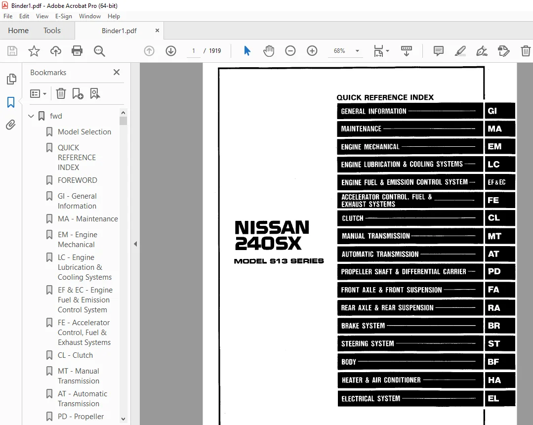
QUICK REFERENCE INDEX 1
FOREWORD 2
GI – General Information 0
MA – Maintenance 0
EM – Engine Mechanical 0
LC – Engine Lubrication & Cooling Systems 0
EF & EC – Engine Fuel & Emission Control System 0
FE – Accelerator Control, Fuel & Exhaust Systems 0
CL – Clutch 0
MT – Manual Transmission 0
AT – Automatic Transmission 0
PD – Propeller Shaft & Differential Carrier 0
FA – Front Axle & Front Suspension 0
RA – Rear Axle & Rear Suspension 0
BR – Brake System 0
ST – Steering System 0
BF – Body 0
HA – Heater & Air Conditioner 0
EL – Electrical System 0
Foldout 0
Inch to Metric Conversion Table 3
Quick Reference Chart 4
1993_240sx 5
1993 Nissan 240SX 5
SM3E-0S13U0 5
QUICK REFERENCE INDEX 5
QUICK REFERENCE CHART 962
AT 963
QUICK REFERENCE INDEX 0
TABLE OF CONTENTS 963
PREPARATION 964
Special Service Tools 964
PRECAUTIONS 965
Service Notice 965
A/T CONTROL DIAGRAM 966
Hydraulic Control Circuits 966
Electrical Control Chart 967
Mechanical Operation 967
Cross-Sectional View 968
TROUBLE DIAGNOSES 969
Contents 969
TROUBLE DIAGNOSES – A/T Shift Lock System 1039
Shift Lock System Electrical Parts Location 1040
Circuit Diagram For Quick Pinpoint Check 1040
Wiring Diagram 1041
Diagnostic Procedure 1042
Shift Lock Control Unit Inspection Talbe 1051
Component Check 1052
ON-VEHICLE SERVICE 1054
Control Valve Assembly and Accumulators Inspection 1054
Revolution Sensor Replacement 1054
Rear Oil Seal Replacement 1055
Parking Components Inspection 1055
Inhibitor Switch Adjustment 1056
Manual Control Linkage Adjustment 1056
Kickdown Switch Adjustment 1056
REMOVAL AND INSTALLATION 1057
Removal 1057
Installation 1059
MAJOR OVERHAUL 1060
Oil Channel 1062
Locations of Needle Bearings, Thrust Washers and Snap Rings 1063
DISASSEMBLY 1064
Disassembly 1064
REPAIR FOR COMPONENT PARTS 1075
Oil Pump 1075
Control Valve Assembly 1079
Control Valve Upper Body 1085
Control Valve Lower Body 1091
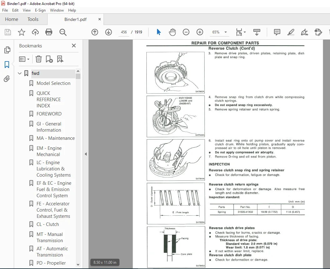
Reverse Clutch 1093
High Clutch 1097
Forward and Overrun Clutches 1099
Low & Reverse Brake 1103
Forward Clutch Drum Assembly 1107
Rear Internal Gear and Forward Clutch Hub 1109
Band Servo Piston Assembly 1112
Parking Pawl Components 1116
ASSEMBLY 1118
Assembly 1118
Adjustment 1122
Assembly 1126
SERVICE DATA AND SPECIFICATIONS (S D S ) 1136
General Specifications 1136
Specifications and Adjustment 1136
BF 1140
QUICK REFERENCE INDEX 0
TABLE OF CONTENTS 1140
GENERAL SERVICING 1141
Precautions 1141
Circuit Breaker Inspection 1141
Clip and Fastener 1141
BODY END 1144
Body Front End 1144
Body Rear End and Opener 1145
DOOR 1148
Power Window 1150
Power Door Lock 1152
INSTRUMENT PANEL 1154
INTERIOR AND EXTERIOR 1156
Interior 1156
Exterior 1160
SEAT 1165
Front Seat 1165
Rear Seat 1166
AUTOMATIC SEAT BELT SYSTEM 1167
Unit Location 1167
Replacement of Rear Switch Assembly 1169
Wiring Diagram 1171
Description 1173
TROUBLE DIAGNOSES – Automatic seat belt system 1175
Contents 1175
SUN ROOF 1195
Electrical Sun Roof 1195
Wiring Diagram 1197
Manual Sun Roof 1198
WINDSHIELD AND WINDOWS 1199
Windshield 1199
Back Window – Coupe 1200
Back Door Window – Fastback 1201
Side Window 1202
MIRROR 1204
Door Mirror 1204
REAR COMBINATION LAMP 1205
FRONT AND REAR AIR SPOILER 1206
BODY ALIGNMENT 1208
Engine Compartment 1208
Underbody 1210
BR 1212
QUICK REFERENCE INDEX 0
TABLE OF CONTENTS 1212
PRECAUTIONS AND PREPARATION 1213
Precautions 1213
Special Service Tools 1213
CHECK AND ADJUSTMENT 1214
Checking Brake Fluid Level 1214
Checking Brake System 1214
Changing Brake Fluid 1214
BRAKE HYDRAULIC LINE 1215
Bleeding Procedure 1215
Removal and Installation 1216
Inspection 1216
BRAKE PEDAL AND BRACKET 1217
Removal and Installation 1217
Inspection 1217
Adjustment 1218
BRAKE BOOSTER 1219
Removal and Installation 1219
Inspection 1219
VACUUM PIPING 1220
Removal and Installation 1220
Inspection 1220
MASTER CYLINDER 1221
Removal and Installation 1221
FRONT DISC BRAKE (CL22VB, CL25VA) 1222
Pad Replacement 1223
Removal and Installation 1223
Disassembly 1223
Inspection 1223
Assembly 1224
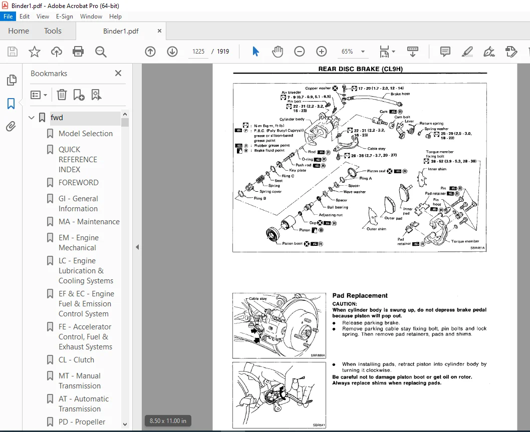
REAR DISC BRAKE (CL9H) 1225
Pad Replacement 1225
Removal and Installation 1226
Disassembly 1226
Inspection 1227
Assembly 1227
Inspection 1228
PARKING BRAKE CONTROL 1229
Removal and Installation 1229
Inspection 1229
Adjustment 1230
ANTI-LOCK BRAKING SYSTEM 1231
System Components 1231
Hydraulic Circuit 1231
Wiring Diagram 1232
Removal and Installation 1233
TROUBLE DIAGNOSES 1234
Contents 1234
SERVICE DATA AND SPECIFICATIONS (S D S ) 1257
General Specifications 1257
Inspection and Adjustment 1257
CL 1258
QUICK REFERENCE INDEX 0
TABLE OF CONTENTS 1258
PRECAUTIONS AND PREPARATION 1259
Precautions 1259
Special Service Tools 1259
Commercial Service Tools 1259
CLUTCH SYSTEM 1260
INSPECTION AND ADJUSTMENT 1261
Adjusting Clutch Pedal 1261
Bleeding Procedure 1262
HYDRAULIC CLUTCH CONTROL 1263
Clutch Master Cyliinder 1263
Operating Cylinder 1264
CLUTCH RELEASE MECHANISM 1265
CLUTCH DISC AND CLUTCH COVER 1267
Clutch Cover and Flywheel 1267
Clutch Disc 1268
SERVICE DATA AND SPECIFICATIONS (S D S ) 1269
General Specifications 1269
Inspection and Adjustment 1269
EC 1270
QUICK REFERENCE INDEX 0
TABLE OF CONTENTS 1270
PREPARATION AND PRECAUTIONS 1272
Special Service Tool 1272
Precautions 1273
ENGINE AND EMISSION CONTROL OVERALL SYSTEM 1274
ECCS Component Parts Location 1274
System Diagram 1275
System Chart 1276
Vacuum Hose Drawing 1277
Circuit Diagram 1278
ENGINE AND EMISSION CONTROL PARTS DESCRIPTION 1279
Engine Control Module (ECM)-ECCS Control Module 1279
Crankshaft Position Sensor (CKPS) 1279
Mass Air Flow Sensor (MAFS) 1279
Engine Coolant Temperature Sensor (ECTS) 1280
Throttle Position Sensor (TP) & Soft/Hard Closed Throttle Position (CTP) Switch 1280
Fuel Injector 1281
Pressure Regulator 1281
Oxygen Sensor (O2S) 1281
Fuel Pump 1281
Ignition Coil with Power Transistor 1282
Idle Air Control Valve (IACV)=Air Regulator 1282
Idle Air Adjusting (I A A ) Unit 1282
Edle Air Control Valve (IACV)-Auxiliary Air Control (AAC) Valve 1282
Power Steering Oil Pressure Switch 1282
Knock Sensor (KS) 1283
Fuel Filter 1283
Data Link Connector for CONSULT 1283
Exhaust Gas Recirculation (EGR) Valve 1283
EGR Control (EGRC)-BPT Valve 1284
Pulsed Secondary Air Injection (PAIR) Valve (PAIR valve) 1284
Pulsed Secondary Air Injection (PAIRC) Solenoid Valve 1284
EGR and Canister Control Solenoid Valve 1284
S C V Control Solenoid Valve 1284
Carbon Canister 1284
EGR Temperature Sensor (For California models) 1285
ENGINE AND EMISSION CONTROL SYSTEM DESCRIPTION 1286
Multiport Fuel Injection (MFI) System 1286
Distributor Ignition (DI) System 1289
Idle Air Control (IACV) System 1291
Pulsed Secondary Air Injection (PAIR) Valve (PAIR valve) Control 1292
Exhaust Gas Recirculation (EGR) System 1292
Fuel Pump Control 1293
Idle Air Control Valve (IACV)-Air Regulator Control 1293
Acceleration Cut Control 1294
Swirl Control Valve (S C V ) Control 1294
Condenser Fan Control 1295
Fail-safe System 1295
IDLE SPEED/IGNITION TIMING/IDLE MIXTURE RATIO INSPECTION 1297
TROUBLE DIAGNOSES 1302
Contents 1302
TROUBLE DIAGNOSES 1304
MULTIPORT FUEL INJECTION SYSTEM INSPECTION 1438
Releasing Fuel Pressure 1438
Fuel Pressure Check 1438
Injector Removal and Installation 1439
EVAPORATIVE EMISSION SYSTEM 1440
Description 1440
Inspection 1440
CRANKCASE EMISSION CONTROL SYSTEM 1442
Description 1442
Inspection 1442
SERVICE DATA AND SPECIFICATIONS (S D S ) 1444
General Specifications 1444
Inspection and Adjustment 1444
EL 1445
QUICK REFERENCE INDEX 0
TABLE OF CONTENTS 1445
HARNESS CONNECTOR 1447
Description 1447
STANDARDIZED RELAY 1448
Description 1448
POWER SUPPLY ROUTING 1450
Wiring Diagram 1450
Fuse 1451
Fusible Link 1451
BATTERY 1452
How to Handle Battery 1452
Service Data and Specifications (S D S ) 1455
STARTING SYSTEM 1456
Wiring Diagram 1456
Construction 1457
Service Data and Specifications (S D S ) 1457
CHARGING SYSTEM 1458
Wiring Diagram 1458
Construction 1459
Service Data and Specifications (S D S ) 1460
COMBINATION SWITCH 1461
Combination Switch/Check 1461
Replacement 1462
Steering Switch/Check 1463
HEADLAMP 1464
Schematic 1464
Wiring Diagram 1465
Description 1466
Constructions 1470
Assembly 1471
Installation and Adjustment 1471
Headlamp Motor Check 1472
Aiming Adjustment 1473
EXTERIOR LAMP 1474
Daytime Light/Description & Schematic 1474
Daytime Light/Wiring Diagram 1475
Clearance, License, Tail and Stop Lamps/Wiring Diagram 1476
Back-up Lamp/Wiring Diagram 1478
Turn Signal and Hazard Warning Lamps/Wiring Diagram 1479
Combination Flasher Unit Check 1480
Bulb Specifications 1480
INTERIOR LAMP 1481
Illumination/Wiring Diagram 1481
Interior Lamp/Wiring Diagram 1482
METER AND GAUGES 1483
Combination Meter 1483
Combination Meter/Wiring Diagram 1486
Speedometer, Tachometer, Temp and Fuel Gauges/Wiring Diagram 1487
Inspection/Fuel Gauge and Water Temperature Gauge 1488
Fuel Tank Gauge Unit Check 1489
Oil Pressure Switch Check 1489
Speed Sensor Signal Check 1489
WARNING LAMPS AND CHIME 1490
Warning Lamps/Schematic 1490
Warning Lamps/Wiring Diagram 1491
Warning Chime/Wiring Diagram 1492
Diode Check 1493
Warning Chime Check 1493
TIME CONTROL SYSTEM 1494
Schematic 1494
Wiring Diagram 1495
Description 1496
Trouble-shooting 1497
WIPER AND WASHER 1503
Front Wiper and Washer/Wiring Diagram 1503
Rear Wiper and Washer/Wiring Diagram 1504
Wiper and Washer Adjustment 1505
Washer Nozzle Adjustment 1506
Check Valve 1506
Wiper Amplifier Check 1507
HORN, CIGARETTE LIGHTER AND CLOCK 1508
Wiring Diagram 1508
REAR WINDOW DEFOGGER 1509
Wiring Diagram 1509
Filament Check 1510
Filament Repair 1511
AUDIO AND POWER ANTENNA 1512
Audio/Wiring Diagram 1512
Power Antenna/Wiring Diagram 1513
Radio Fuse Check 1513
Location of Antenna 1514
Antenna Rod Replacement 1514
Window Antenna Repair 1515
AUTOMATIC SPEED CONTROL DEVICE (A S C D ) 1516
Wiring Diagram 1516
Schematic 1518
Trouble Diagnoses 1519
A S C D Wire Adjustment 1527
LOCATION OF ELECTRICAL UNITS 1531
Engine Compartment 1531
Passenger Compartment 1532
HARNESS LAYOUT 1534
Outline 1534
Instrument Harness 1535
Back Door Harness 1535
Main Harness 1536
Engine Room Harness 1542
Engine Room Harness No 2 1545
E F I Harness 1546
Room Lamp and Sun Roof Harness 1547
Door Harness L H 1548
Door Harness R H 1548
SUPER MULTIPLE JUNCTION (S M J ) 0
Disconnecting and Connecting 0
Terminal Arrangement 1
EM 1549
QUICK REFERENCE INDEX 0
TABLE OF CONTENTS 1549
PRECAUTIONS 1550
Parts Requiring Angular Tightening 1550
Liquid Gasket Application Procedure 1550
PREPARATION 1551
Special Service Tools 1551
Commercial Service Tools 1553
OUTER COMPONENT PARTS 1554
COMPRESSION PRESSURE 1556
Measurement of Compression Pressure 1556
OIL PAN 1557
Removal 1557
Installation 1558
TIMING CHAIN 1559
Removal 1561
Inspection 1563
Installation 1564
OIL SEAL REPLACEMENT 1567
CYLINDER HEAD 1569
Removal and Installation 1570
Disassembly 1570
Inspection 1570
Assembly 1575
Valve Clearance 1576
ENGINE REMOVAL 1578
Removal 1579
CYLINDER BLOCK 1580
Disassembly 1581
Inspection 1582
Assembly 1588
SERVICE DATA AND SPECIFICATIONS (S D S ) 1591
General Specifications 1591
Inspection and Adjustment 1591
FA 1599
QUICK REFERENCE INDEX 0
TABLE OF CONTENTS 1599
PRECAUTIONS AND PREPARATION 1600
Precautions 1600
Special Service Tools 1600
Commercial Service Tools 1601
FRONT AXLE AND FRONT SUSPENSION 1602
ON-VEHICLE SERVICE 1603
Front Axle and Front Suspension Parts 1603
Front Wheel Bearing 1604
Front Wheel Alignment 1604
FRONT AXLE 1606
Wheel Hub and Knuckle 1606
Baffle Plate 1608
FRONT SUSPENSION 1609
Coil Spring and Strut Assembly 1610
Tension Rod and Stabilizer Bar 1611
Transverse Line and Lower Ball Joint 1612
SERVICE DATA AND SPECIFICATIONS (S D S ) 1613
General Specifications 1613
Inspection and Adjustment 1614
FE 1615
QUICK REFERENCE INDEX 0
TABLE OF CONTENTS 1615
ACCELERATOR CONTROL SYSTEM 1616
Adjusting Accelerator Cable 1616
FUEL SYSTEM 1617
EXHAUST SYSTEM 1618
Foldout 1619
QUICK REFERENCE INDEX 0
ELECTRICAL SYSTEM 1
SUPER MULTIPLE JUNCTION (S M J ) 1619
Disconnecting and Connecting 1619
Terminal Arrangement 1620
1993 NISSAN 240SX ECCS WIRING DIAGRAM 1621
1993 NISSAN 240SX CIRCUIT DIAGRAM 1625
GI 1629
QUICK REFERENCE INDEX 0
TABLE OF CONTENTS 1629
PRECAUTIONS 1630
General Precautions 1630
Precautions for Multiport Fuel Injection System or E C C S Engine 1631
Precautions for Three Way Catalyst 1632
Precautions for Fuel 1632
HOW TO USE THIS MANUAL 1633
HOW TO READ WIRING DIAGRAMS 1635
HOW TO FOLLOW FLOW CHART IN TROUBLE DIAGNOSES 1638
CONSULT CHECKING SYSTEM 1641
Function and System Application 1641
Checking Equipment 1641
IDENTIFICATION INFORMATION 1642
Model Variation 1642
Identification Number 1643
Dimensions 1645
Wheels and Tires 1645
LIFTING POINTS AND TOW TRUCK TOWING 1646
Garage Jack and Safety Stand 1646
2-pole Lift 1646
Tow Truck Towing 1646
TIGHTENING TORQUE OF STANDARD BOLTS 1648
HA 1649
QUICK REFERENCE INDEX 0
TABLE OF CONTENTS 1649
PRECAUTIONS 1650
Precautions for the Handling of Refrigerant 1650
Precautions for Refrigerant Connection 1651
Precautions for Servicing Compressor 1652
DESCRIPTION – Overall System 1653
Control Operation 1653
Component Layout 1654
Air Flow 1655
Air Flow – Max Cold Door Operation System 1656
DESCRIPTION – Refrigeration System 1657
Refrigeration Cycle 1657
Refrigerant Lines 1658
V-5 Variable Displacement Compressor 1659
Acceleration Cut System 1664
PREPARATION 1665
Special Service Tools 1665
Service Tools 1666
DISCHARGING, EVACUATING, CHARGING AND CHECKING 1672
Work Procedure 1672
Setting of Service Tools 1673
Discharging 1674
Evacuation 1675
Charging Refrigerant 1676
Inspection for Refrigerant Leaks 1678
Removal of Service Tools 1679
Sight Glass Inspection for System 1680
SERVICE PROCEDURES 1682
Refrigerant Lines 1682
Compressor Mounting 1683
Thermo Control Amp 1683
Belt Tension 1683
Fast Idle Control Device (F I C D ) 1683
Condenser and Condenser Fan Motor 1684
LUBRICATION OIL – Checking and Adjusting 1687
Lubrication oil 1687
Maintenance of Oil Quantity in Compressor 1687
Checking and Adjustring 1687
COMPRESSOR – Model V-5 (CALSONIC make) 1689
Removing Magnet Clutch Assembly 1689
Installation of Magnet Clutch Assembly 1690
Gap Adjusting Procedure 1693
DIAGNOSES – Overall System 1694
How to Perform Trouble Diagnoses for Quick and Accurate Repair 1694
Operational Check 1695
Performance Chart 1697
Performance Test Diagnoses 1698
TROUBLE DIAGNOSES 1703
Contents 1703
SYSTEM DESCRIPTION – Push Control 1736
Push Control System 1736
Intake Door Motor 1737
Mode Door Motor 1737
Removal and Installation 1737
Overhaul – Push control unit assembly 1738
SERVICE DATA AND SPECIFICATIONS (S D S ) 1740
General Specifications 1740
Inspection and Adjustment 1740
LC 1741
QUICK REFERENCE INDEX 0
TABLE OF CONTENTS 1741
PREPARATION 1742
Special Service Tools 1742
ENGINE LUBRICATION SYSTEM 1743
Lubrication Circuit 1743
Oil Pressure Check 1743
Oil Pump 1744
ENGINE COOLING SYSTEM 1746
Cooling Circuit 1746
System Check 1746
Water Pump 1747
Thermostat 1748
Radiator 1749
Cooling Fan 1749
SERVICE DATA AND SPECIFICATIONS (S D S ) 1750
Engine Lubrication System 1750
Engine Cooling System 1750
MA 1751
QUICK REFERENCE INDEX 0
TABLE OF CONTENTS 1751
GENERAL MAINTENANCE 1752
PERIODIC MAINTENANCE 1754
Schedule 1 1755
Schedule 2 1756
RECOMMENDED LUBRICANTS AND FLUIDS 1757
Lubricants and Fluids 1757
SAE Viscosity Number 1757
ENGINE MAINTENANCE 1758
Checking Drive Belts 1758
Changing Engine Coolant 1759
Checking Fuel Lines 1760
Changing Fuel Filter 1760
Changine Air Cleaner Filter 1761
Changing Engine Oil 1761
Changing Oil Filter 1762
Changing Spark Plugs 1762
Checking Vapor Lines 1762
CHASSIS AND BODY MAINTENANCE 1763
Checking Exhaust System 1763
Checking Clutch Fluid Level and Leaks 1763
Checking M/T Oil 1763
Changing M/T Oil 1763
Checking A/T Fluid 1763
Changing A/T Fluid 1764
Checking Differential Gear Oil 1764
Changing Differential Gear Oil 1764
Balancing Wheels 1764
Tire Rotation 1764
Checking Brake Fluid Levels and Leaks 1765
Checking Brake Lines and Cables 1765
Checking Disc Brake 1765
Checking Steering Gear and Linkage 1765
Checking Power Steering Fluid and Lines 1766
Checking SUPER HICAS Linkage (With SUPER HICAS system) 1766
Lubricating Locks, Hinges and Hood Latches 1767
Checking Seat Belts, Buckles, Retractors, Anchors and Adjusters 1767
SERVICE DATA AND SPECIFICATIONS (S D S ) 1768
Engine Maintenance 1768
Chassis and Body Maintenance 1768
MT 1769
QUICK REFERENCE INDEX 0
TABLE OF CONTENTS 1769
PREPARATION 1770
Special Service Tools 1770
Commercial Service Tool 1771
ON-VEHICLE SERVICE 1772
Replacing Rear Oil Seal 1772
Check of Position Switches 1772
REMOVAL AND INSTALLATION 1773
Removal 1773
Installation 1774
MAJOR OVERHAUL 1775
Case Components 1775
Gear Components 1776
Shift Control Components 1777
DISASSEMBLY 1778
Case Components 1778
Shift Control Components 1779
Gear Components 1780
INSPECTION 1783
Shift Control Components 1783
Gear Components 1783
ASSEMBLY 1785
Gear Components 1785
Shift Control Components 1791
Case Components 1793
SERVICE DATA AND SPECIFICATIONS (S D S ) 1795
General Specifications 1795
Inspection and Adjustment 1796
PD 1797
QUICK REFERENCE INDEX 0
TABLE OF CONTENTS 1797
PREPARATION 1798
Special Service Tools 1798
PROPELLER SHAFT 1801
On-vehicle Service 1802
Removal 1802
Installation 1802
Inspection 1803
Disassembly 1803
Assembly 1804
FINAL DRIVE 1805
ON-VEHICLE SERVICE/REMOVAL AND INSTALLATION 1805
Front Oil Seal Replacement 1805
Side Oil Seal Replacement 1805
Removal 1806
Installation 1806
FINAL DRIVE 1808
DISASSEMBLY 1809
Pre-inspection 1809
Differential Carrier 1809
Differential Case 1811
INSPECTION 1813
Ring Gear and Drive Pinion 1813
Bearing 1813
Differential Case Assembly 1813
ADJUSTMENT 1814
Side Bearing Preload 1814
Pinion Gear Height and Pinion Bearing Preload 1815
Tooth Contact 1820
ASSEMBLY 1821
Differential Case 1821
Differential Carrier 1823
SERVICE DATA AND SPECIFICATIONS (S D S ) 1827
Propeller Shaft 1827
Final Drive 1827
RA 1829
QUICK REFERENCE INDEX 0
TABLE OF CONTENTS 1829
PRECAUTIONS AND PREPARATION 1830
Precautions 1830
Special Service Tools 1830
Commercial Service Tools 1831
REAR AXLE AND REAR SUSPENSION 1832
ON-VEHICLE SERVICE 1833
Rear Axle and Rear Suspension Parts 1833
Rear Wheel Bearing 1833
Rear Wheel Alignment 1833
Drive Shaft 1834
REAR AXLE AND REAR SUSPENSION ASSEMBLY 1835
REAR AXLE 1836
Wheel Hub and Axle Housing 1836
Drive Shaft 1839
REAR SUSPENSION 1845
Coil Spring and Shock Absorber 1846
Multi-link and Lower Ball Joint 1847
Stabilizer Bar 1848
SUPER HICAS 1849
Rear Wheel Alignment 1849
Rear Axle Housing Ball Joint 1849
SERVICE DATA AND SPECIFICATIONS (S D S ) 1850
General Specifications 1850
Inspection and Adjustment 1851
ST 1852
QUICK REFERENCE INDEX 0
TABLE OF CONTENTS 1852
PRECAUTIONS AND PREPARATION 1853
Precautions 1853
Special Service Tools 1853
Commercial Service Tools 1854
ON-VEHICLE SERVICE 1855
Checking Steering Wheel Play 1855
Checking Neutral Position on Steering Wheel 1855
Front Wheel Turning Angle 1855
Checking Gear Housing Movement 1856
Adjusting Rack Retainer 1856
Checking and Adjusting Drive Belts 1856
Checking Fluid Level 1856
Checking Fluid Leakage 1856
Bleeding Hydraulic System 1857
Checking Steering Wheel Turning Force 1857
Checking Hydraulic System 1858
STEERING WHEEL AND STEERING COLUMN 1859
Removal 1859
Installation 1860
Disassembly and Assembly 1861
Inspection 1862
POWER STEERING GEAR AND LINKAGE (Model PR24SC) 1863
Removal and Installation 1863
Disassembly and Assembly 1865
Disassembly 1866
Inspection 1867
Assembly 1868
Adjustment 1872
POWER STEERING OIL PUMP 1874
Disassembly and Assembly 1874
Pre-disassembly Inspection 1874
Disassembly 1874
Inspection 1875
Assembly 1875
SUPER HICAS SYSTEM 1877
HICAS Component Parts Location 1877
System Diagram 1877
On-vehicle Service 1878
Repair of Component Parts 1880
Trouble Diagnoses 1889
SERVICE DATA AND SPECIFICATIONS (S D S ) 1918
General Specifications 1918
Inspection and Adjustment 1918
Need help? Contact: [email protected]
https://vimeo.com/849386771?share=copy
DESCRIPTION:
1933 NISSAN 240SX S13 Series Service Manual PDF DOWNLOAD
FOREWORD
- This manual contains maintenance and repair procedures for the 1993 Nissan 240SX. In order to assure your safety and the efficient functioning of the vehicle, this manual should be read thoroughly.
- It is especially important that the PRECAUTIONS in the GI section be completely understood before starting any repair task. All information in this manual is based on the latest product information at the time of publication.
- The right is reserved to make changes in specifications and methods at any time without notice.
HOW TO USE THIS MANUAL
PLEASE NOTE:
- This is the same manual used by the dealers to diagnose and troubleshoot your vehicle
- You will be directed to the download page as soon as the purchase is completed. The whole payment and downloading process will take anywhere between 2-5 minutes
- Need any other service / repair / parts manual, please feel free to contact [email protected] . We still have 50,000 manuals unlisted
G.P