1981 Kawasaki Drifter SB340-A2 Supplement Manual
Original price was: $69.95.$16.95Current price is: $16.95.
1981 Kawasaki Drifter SB340-A2 Supplement Manual – PDF DOWNLOAD
Description
1981 Kawasaki Drifter SB340-A2 Supplement Manual – PDF DOWNLOAD
Customer Support: [email protected]
Image Preview:
Description:
1981 Kawasaki Drifter SB340-A2 Supplement Manual – PDF DOWNLOAD
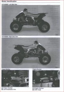
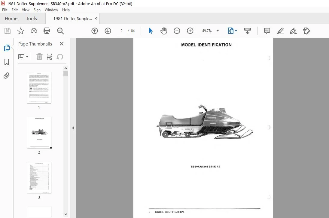
- This Drifter SB340-A2, SB440-A5 Shop Manual Supplement is designed to be used in conjunction with the Drifter SA340-A4, SB440-A4, SC340-A 1 Shop Manual (PIN 99963-3511). The maintenance and repair procedures described in this Supplement are only those that are unique to the SB340-A2 and SB440-A5 models. Most service operations for these models remain identical to those described in the base Shop Manual.
- Complete and proper servicing of the SB340-A2 and SB440-A5 models therefore requires both this Supplement and the base Shop Manual. The base Shop Manual and this Supplement are designed primarily for use by snowmobile mechanics in a properly equipped shop. However, they contain enough detail and basic information to make them useful to the snowmobile owner who desires to perform his own basic maintenance and repair work. A basic knowledge of mechanics, the proper use of tools, and workshop procedures must be understood in order to carry out maintenance and repair satisfactori ly.
- Whenever the owner has insufficient experience or doubts his ability to do the work, the adjustments, maintenance, and repair should be carried out only by qualified mechanics. In order to perform the work efficiently and to avoid costly mistakes, the mechanic should read the text, thoroughly familiarize himself with the procedures before starting work, and then do the work carefully in a clean area.
- Whenever special tools and equipment are specified, makeshift tools or equipment should not be used. Precision measurements can only be made if the proper instruments are used, and the use of substitute tools may adversely affect safe operation of the snowmobile. Whenever you see the symbols shown below, heed their instructions! Always follow safe operating and maintenance practices.
- WARNING I This warning symbol identifies special instructions or procedures which, if not correctly followed, could result in personal injury, or loss of life. This caution symbol identifies special instructions or procedures which, if not strictly observed, could result in damage to, or destruction of equipment NOTE: indicates points of particular interest for more efficient and convenient operation.
- All rights reserved. No part of this publication may be reproduced, stored in a retrieval system, or transmitted in any form or by any means, electronic mechanical photocopyin g, recording or otherwise, without the prior written permission of the Technical Publications Department/Kawasaki Motors Corp., U.S.A.
- No liability can be accepted for any inaccuracies or omissions in this publication, although every possible care has been taken to make it as complete and accurate as possible. All procedures and speCifications subject to change without prior notice or obligation.
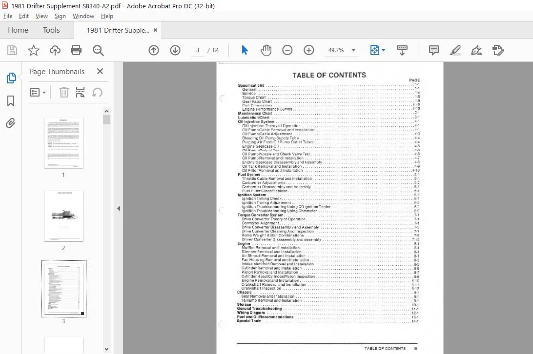
Table Of Contents:
1981 Kawasaki Drifter SB340-A2 Supplement Manual – PDF DOWNLOAD
Specifications …. … … . . .. ……. . … … .. ….. .. … ………… … .. ………. . … . . 1-1
General .. . ……………… . … . ………… .. . … … ….. …. .. ….. ….. . … ….. 1-1
Service .. . ………………………………………………… .. ……. .. .. …. 1-4 c Torque Chart ……………….. . ….. . …………… . ……….. . … ……… .. … 1-6
Gear Ratio Chart .. .. …. … . . . . ………. .. . .. . … . ……. . ………….. . .. … . ….. 1-9
Port Dimensions .. . . ……. ………. ……. . . …… … . .. . . .. .. … . .. ……….. … 1-10
Engine Performance Curves .. ….. .. … … .. …… . …… .. … . …. …. ………. … .. 1-10
Maintenance Chart . … …. …… … ….. .. ….. …… …. .. . … …… … .. ……. …… 2-1
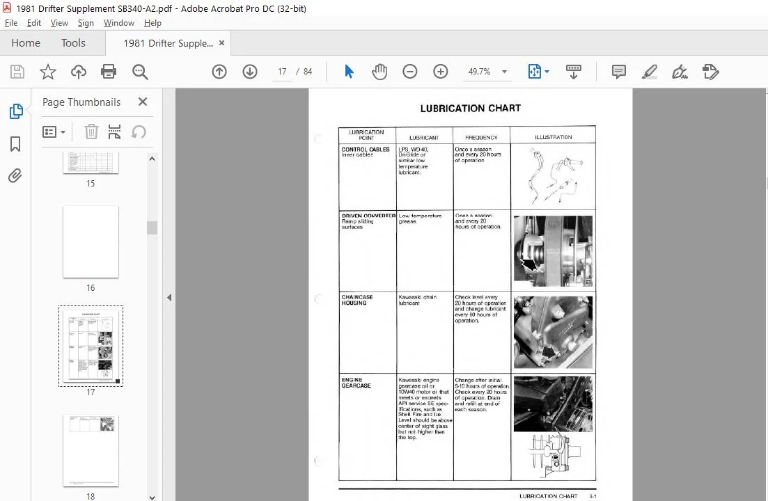
Lubrication Chart …. ….. . .. . … . …. ….. ….. …….. .. …. . ……… .. ……….. . . 3-1
Oil Injection System …. …………. ….. … …… . …. ….. . ……. ………………. 4-1
Oil Injection Theory of Operation … . .. . ……………………. … ……. ………. .. . 4-1
Oil Pump Cable Removal and Installation … ……. …… ……… .. ………………… 4-1
Oil Pump Cable Adjustment ……. … …. . . .. . . …………………………. . . . . . … .4-3
Bleeding Oil Pump Supply Tube …………. . . ………. ……. ……. ….. … . …….. 4-4
Purging Air From Oil Pump Outlet Tubes …… … . .. …… …………….. . . ……….. .4-4
Engine Gearcase Oil .. . ………. …….. … ….. . . . … …………… . …… .. …. . .. 4-5
Oil Pump Output Test . . . . ……….. …. . ….. . …. …… .. … .. …………………. 4-6
Oil Pump Nozzle and Check Valve Test . …….. ……. . .. . ……………………. . ….. 4-6
Oil Pump Removal and Installation … . . . .. . …. . .. . ………. . ………. …… . ……… 4-7
Engine Gearcase Disassembly and Assembly .. . …………. … . ….. .. … . ………….. 4-8
Oil Tank Removal and In stallation …………… . .. … . ……. . … . …………. . . ….. .4-9
Oil Filter Removal and Installation …….. …. . . …. …….. . ……….. ……. … …. . 4-10
Fuel System . . . …. . . .. .. ……… . . .. …………. . …… .. … . .. … . . …. … . . . … . .. 5-1
Throttle Cable Removal and In stallation …. …….. .. . .. … … …….. . …….. . … … . .. 5-1
Carburetor Adjustments . . . . ………… . . . .. . …. . .. . . … .. . …. ………. . . . …….. . 5-2
Carburetor Disassembly and Assembly . .. . ………………………. . … ………….. 5-3
Fuel Fi lter Clean/Replace …………. …….. ……… . ………………. . . ……. .. . 5-4
Ignition System .. . . . .. … . .. ……… . . … …. . . …… ………….. .. ………. . . ….. 6-1
Ignition Tim ing Check . . . ….. . …… .. …………………………. . …. … . …. . . .. 6-1
Ignition Timing Adjustment .. . ….. ………… . . .. …. … . . … .. ……… . .. . . . ……. 6-2
( Ignition Troubleshooting Using CD Ignition Tester . .. .. .. .. …. …. . . . . . . .. ………… …. 6-2
Ignition Troubleshooting Using Ohmmeter . . … …………………. ……. … . . ….. … 6-9
Torque Converter System …………… … …………… .. . …. .. ……… . … ……… 7-1
Drive Converter Theory of Operation .. …. … … . . . .. .. . . . .. . ……… . .. . … .. … . .. .. . . 7-1
Converter Alignment …….. …….. …. .. .. . …….. …… . …. …….. ………….. 7-1
Drive Converter Disassembly and Assembly …………… . …. ………. … . …. …… .. 7-3
Drive Converter Cleaning And Inspection . .. .. . . . . …… …………….. . . . … ………. 7-7
Ramp Weight & Bolt Combinations ……………………………….. .. .. … . . . . ….. 7-9
Driven Converter Disassembly and Assembly ………………………………… … .. 7-12
Engine . …. . ….. . ….. …. ……………. . …. . … . . . .. . ……. . …. …… ……… 8-1
Muffler Removal and In stallation ….. …. .. . ………….. . ……. . …….. …… … … . 8-1
Si lencer Removal and In stallation ………… . …….. .. …. .. . …….. .. . . . … … …… 8-1
Air Shroud Removal and Installation ………………….. . ………… …. …….. ….. 8-1
Fan Housing Removal and In stallation. . . . . . . . . . . . . . . . . . . . . . . . . . . . . . . . . . . . . . .. . .. . …… 8-3
Intake Manifold Removal and In stallation .. . . … . .. . …. . ……. . . .. .. … .. . …. ……… 8-5
Cyl i nder Removal and In stallation . …………. . ….. .. …….. .. …. .. . . . …. …. …… 8-6
Piston Removal and Installation .. . …… . ……………………… … .. ……… . .. . . 8-7
Cylinder Head/Cylinder/Piston Inspection . …….. .. . . .. ……….. .. .. ………… .. . … 8-8
Engine Removal and Installation . … ……….. . .. . . .. . …. . ……. . … .. ……….. … 8-10
Crankshaft Removal and Installat ion …… … . . …. . …….. . . ……………………. 8-11
Crankshaft Inspection ….. .. .. ….. . . …. ………………………. . ….. ….. …. 8-12
Chassis .. . ……. … …………… .. . . ….. .. …….. .. …. .. …. . …. .. . ……. . …. 9-1
Seat Removal and Installation . ……. . . . ……………….. …. …. . …….. . . .. …… 9-1
Taillamp Removal and Installation … ………… . .. .. . . . .. …. . .. … …….. ……. …. 9-1
Storage ….. … ………… . . … ……. …… .. .. ……………. …. . …………. . . 10-1
General Troubleshooting . … ….. . ……… .. …………………….. .. . …… ……. 11 -1
Wiring Diagram ………………………… …. …….. … ………. ….. . . ….. . … 12-1
Fuel and Oil Recommendations …… . …. . ………………………. ….. …. . . …. . . 13-1
Special Tools . .. .. … … .. .. …….. . ………… . ….. . … ……………………… 14-1
Please Note:
- This is the SAME MANUAL used by the dealerships to diagnose your vehicle
- No waiting for couriers / posts as this is a PDF manual and you can download it within 2 minutes time once you make the payment.
- Your payment is all safe and the delivery of the manual is INSTANT – You will be taken to the DOWNLOAD PAGE.
- So have no hesitations whatsoever and write to us about any queries you may have : heydownloadss @gmail.com