Trusted Business
Verified & Licensed
Virus Free Files
100% Safe Downloads
Secure Payment
SSL Protected
Instant Delivery
Available Immediately
1985 NISSAN 300ZX Z31 Series Service Manual PDF DOWNLOAD
$31.95
1985 NISSAN 300ZX Z31 Series Service Manual PDF DOWNLOAD
Instant PDF Download
Available immediately
Save to Your Device
Download & keep forever
Antivirus Scanned
100% virus-free
Trusted Worldwide
175,000+ customers
Description
1985 NISSAN 300ZX Z31 Series Service Manual PDF DOWNLOAD
FILE DETAILS:
1985 NISSAN 300ZX Z31 Series Service Manual PDF DOWNLOAD
Language : English
Pages : 656
Downloadable :Yes
File Type : PDF
IMAGES PREVIEW OF THE MANUAL:
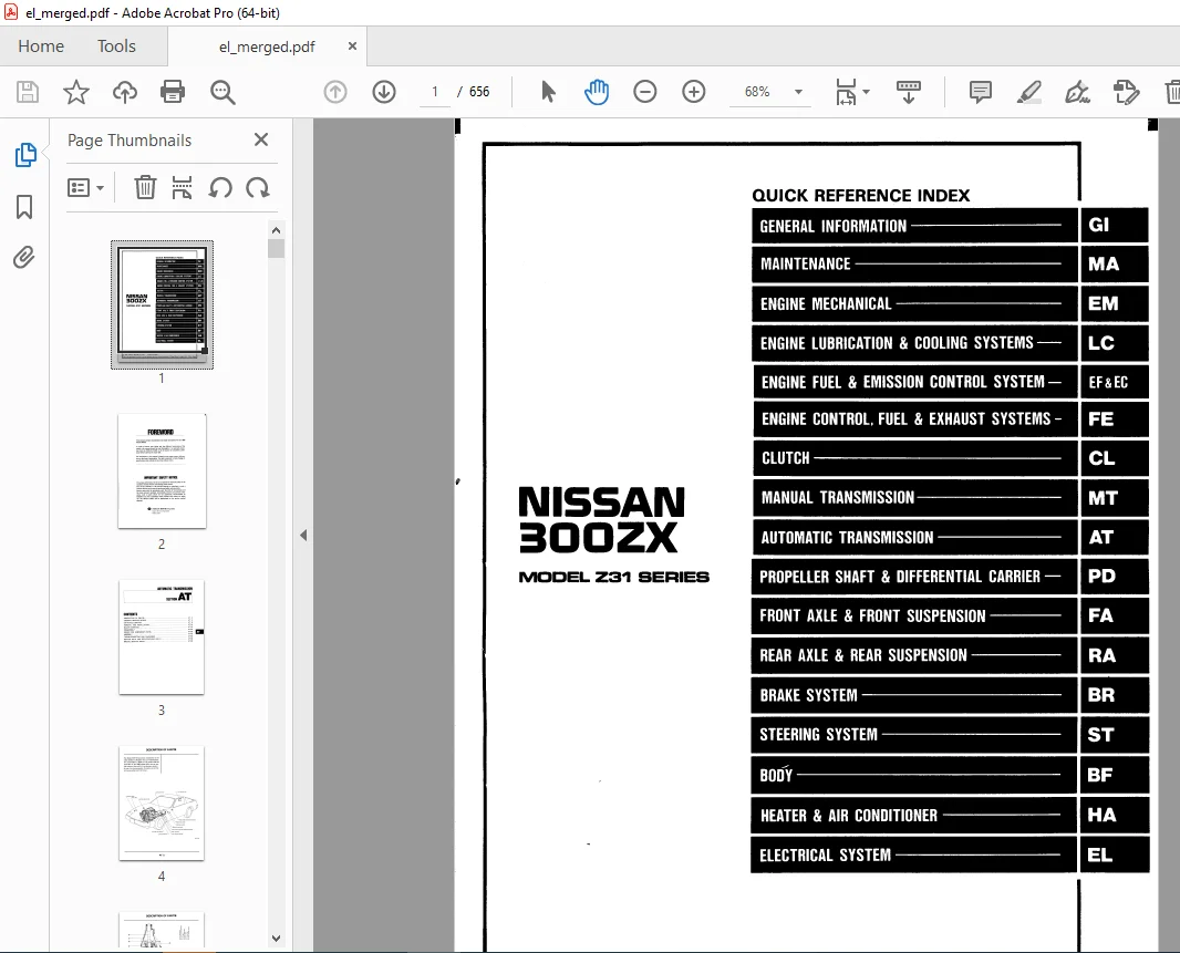
TABLE OF CONTENTS:
1985 NISSAN 300ZX Z31 Series Service Manual PDF DOWNLOAD
Automatic Transmission...........................................  3
	Description..................................................  4
	General Service Notice.......................................  6
		Repair Notes.............................................  6
		Control Valve............................................  6
		Lockup Control Valve and O.D. Cancel Valve...............  7
		Oil Channel..............................................  8
		Mechanical Operation.....................................  9
		Hydraulic Control Circuits............................... 10
	On-Vehicle Service........................................... 11
		Control Valve............................................ 11
		Extension Oil Seal....................................... 12
		Parking Component........................................ 12
		Governor Valve Assembly.................................. 13
		Inhibitor Switch Adjustment.............................. 13
		Manual Linkage Adjustment................................ 14
		Vacuum Diaphragm Rod Adjustment.......................... 15
		Downshift Solenoid....................................... 15
		Kickdown Switch Adjustment............................... 16
		Overdrive and Lockup Control............................. 17
	Removal and Installation..................................... 18
	Major Overhaul............................................... 20
	Disassembly.................................................. 22
	Repair for Component Parts................................... 28
		Oil Pump................................................. 28
		Drum Support............................................. 30
		Control Valve Body....................................... 34
		Oil Distributor.......................................... 38
		Direct Clutch............................................ 39
		Front Clutch............................................. 42
		Rear Clutch (Forward).................................... 45
		Low & Reverse Brake...................................... 46
		Brake Band and Band Servo................................ 47
		Governor................................................. 48
		Accumulator.............................................. 48
		Planetary Carrier........................................ 49
		Connecting Drum Assembly................................. 49
		O.D. One-Way Clutch...................................... 50
	Assembly..................................................... 51
	Trouble-shooting and Diagnoses............................... 65
		Preliminary Checks....................................... 65
		Road Testing............................................. 65
		Road Test Symptom Chart.................................. 70
		Trouble-Shooting Chart................................... 71
		Electrical System/Schematic.............................. 74
		Electrical System/Wiring Diagram......................... 75
		Inspection of A/T Control Unit........................... 76
		Inspection of Lockup Control............................. 78
		Inspection of O.D. Control............................... 80
		Inspection of Parts related to ASCD...................... 81
		Inspection of Kickdown Control........................... 83
		Self Diagnostics......................................... 84
		Pressure Testing......................................... 86
		Stall Testing............................................ 88
	Service Data and Specifications.............................. 90
	Special Service Tools........................................ 94
Body............................................................. 95
	General Servicing............................................ 96
	Body End and Door............................................100
		Front End................................................100
		Rear End.................................................102
		Back Door and Fuel Filler Lid Opener.....................103
		Front Door...............................................104
			Power Window Wiring..................................105
			Power Door Lock Wiring...............................106
	Seat.........................................................107
		Manual Driver Seat.......................................107
		Semi-Power Driver Seat...................................108
		Full Power Driver Seat...................................112
		Front Assist Seat........................................116
		Rear Seat................................................117
	Seat Belt....................................................118
	Instrument...................................................119
	Interior and Exterior........................................120
		Inside Trim..............................................120
		Exterior.................................................122
	Windshield and Windows.......................................126
		Windshield...............................................126
		Back Door Window.........................................128
		Side Window..............................................129
		Repairing Leaks..........................................130
	T-Bar Roof...................................................131
	Mirror.......................................................132
	Rear Air Spoiler and High-mounted Stop Lamp..................133
	Rear Combination Lamp........................................134
	Body Alignment...............................................135
		Engine Compartment.......................................135
		Underbody................................................138
Brake System.....................................................142
	Brake Hydraulic Line.........................................143
		Precautions..............................................143
		Bleeding Procedure.......................................143
		Removal and Installation.................................144
		Inspection...............................................144
	Brake Pedal..................................................145
		Inspection...............................................145
		Adjustment...............................................146
	Master Cylinder..............................................147
	Brake Booster................................................148
		Operating Check..........................................148
		Airtight Check...........................................148
		Removal and Installation.................................148
		Inspection...............................................149
	Front Disc Brake - Caliper...................................150
		Pad Replacement..........................................150
		Removal and Installation.................................151
		Disassembly..............................................151
		Inspection...............................................151
		Assembly.................................................151
	Front Disc Brake - Rotor.....................................152
		Inspection...............................................152
	Rear Disc Brake - Caliper....................................153
		Pad Replacement..........................................154
		Removal and Installation.................................154
		Disassembly..............................................155
		Inspection...............................................156
		Assembly.................................................156
	Rear Disc Brake - Rotor......................................157
		Inspection...............................................157
	Parking Brake................................................158
		Removal..................................................158
		Inspection...............................................158
		Adjustment...............................................159
	Service Data and Specifications..............................160
		General Specifications...................................160
		Inspection and Adjustment................................160
		Tightening Torque........................................161
	Special Service Tool.........................................162
Circuit Diagram (GL & SF)........................................168
Clutch...........................................................172
	Hydraulic Clutch Control.....................................173
		Precautions..............................................173
		Bleeding Procedure.......................................174
		Adjusting Clutch Pedal...................................174
		Clutch Master Cylinder...................................175
		Operating Cylinder.......................................176
		Clutch Damper............................................176
	Clutch Control - Release Bearing.............................177
	Clutch Unit..................................................178
	Service Data and Specifications..............................181
	Special Service Tools........................................183
Electrical System................................................184
	How to read Diagrams.........................................185
	Standardized Relay...........................................188
	Power Supply Routing.........................................189
	Battery......................................................192
		How To Handle Battery....................................192
		Specific Gravity Check...................................194
		Battery Test and Charging Chart..........................195
	Starting System..............................................200
	Starter......................................................201
		Construction.............................................201
		Magnetic Switch Check....................................202
		Pinion/Clutch Check......................................202
		Brush Check..............................................203
		Field Coil Check.........................................203
		Armature Check...........................................204
		Assembly.................................................205
		Service Data and Specifications..........................205
	Charging System..............................................206
		Wiring Diagram - Turbo...................................206
		Wiring Diagram - Non-Turbo...............................207
		Trouble Shooting.........................................208
	Alternator...................................................209
		Construction (Mitsubishi)................................209
		Construction (Hitachi)...................................209
		Removal..................................................210
		Disassembly..............................................210
		Rotor Slip Ring Check....................................210
		Brush Check..............................................211
		Stator Check.............................................211
		Diode Check..............................................212
		Assembly.................................................213
		Service Data and Specifications..........................214
	Combination Switch...........................................215
		Check....................................................215
		Replacement..............................................216
	Instrument Switch............................................217
	Headlamp.....................................................218
		Schematic................................................218
		Wiring Diagram...........................................219
		Operation................................................223
		Description..............................................224
		Trouble Shooting.........................................232
		Removal..................................................233
		Installation.............................................234
		Adjustment...............................................234
		Headlamp Motor Check.....................................235
		Aiming Adjustment........................................235
	Exterior Lamp................................................236
		Clearance, License, Tail, & Stop lamps Wiring Diagram....236
		Auxiliary Driving Lamp Wiring Diagram....................238
		Back-up lamp Wiring Diagram..............................238
		Turn Signal & Hazard Warning lamps Wiring Diagram........239
		Stop and Tail lamp Sensor Check..........................240
		Bulb Specifications......................................240
	Interior Lamp................................................241
		Needle Type Combo Meter (SF & GL)........................241
		Digital Combo Meter (GLL)................................242
		Interior, Luggage and Step lamps.........................243
		Illuminated Entry/Door Key...............................246
	Meter and Gauges.............................................248
		Digital Combo Meter......................................248
			Schematic............................................250
			Wiring Diagram.......................................251
			Display Check........................................253
			Preparation for Trouble Shooting.....................254
			Trouble Shooting.....................................254
			Power Unit Check.....................................260
			Boost Sensor Check...................................260
			Speed Sensor Signal Check............................261
			Fuel Tank Gauge Check................................263
			Water Temp Sensor Check..............................263
			Oil Pressure Sensor Check............................263
		Digital Combo Gauge......................................264
			Schematic............................................264
			Wiring Diagram.......................................265
			Trouble Shooting.....................................266
			Direction Sensor Amplifier Check.....................270
			Compass Input Check..................................270
			Direction Sensor Check...............................271
			Direction Sensor Installation........................271
		Needle Type Combo Meter..................................272
			Tacho, Fuel & Water Temp Gauges......................273
			Fuel Tank Gauge Check................................274
			Speed Sensor Signal Check............................274
			Speedometer Cable Removal............................274
		Needle Type Combo Gauge..................................275
			Oil Temp Sensor Check................................276
			Boost Gauge Trimmer Adjustment.......................276
			Oil Temp, Oil Pressure, Boost & Volt Gauges..........277
	Warning Lamp and Chimes......................................278
		Schematic................................................278
		Warning lamp Wiring Diagram - Digital Combo Meter........279
			Turbo................................................279
			Non-Turbo............................................280
		Warning lamp Wiring Diagram - Needle Type Combo Meter....281
			Turbo................................................281
			Non-Turbo............................................282
			SF Model.............................................283
		Warning Chime Wiring Diagram.............................284
			SF Model.............................................284
			GL & GLL Models......................................285
		Diode Check..............................................286
		Warning Chime Check......................................286
	Voice Warning System.........................................287
		Schematic................................................287
		Wiring Diagram...........................................288
			Needle Type Combo Meter..............................288
			Digital Type Combo Meter.............................289
		Operational Check........................................290
		Trouble Shooting.........................................291
	Time Control System..........................................293
		Schematic................................................293
		Wiring Diagram...........................................294
			SF Model.............................................294
			GL & GLL Models......................................295
			Preparation for Trouble Shooting.....................296
			Power Supply Circuit Check...........................296
			Trouble Shooting.....................................296
	Wiper and Washer.............................................302
		Wiring Diagram...........................................302
		Installation.............................................302
		Washer Nozzle Adjustment.................................303
		Rear Wiper/Washer Wiring Diagram.........................304
		Headlamp Washer Wiring Diagram...........................305
	Horn, Cigarette Lighter, Clock...............................306
	Rear Window Defogger.........................................307
		Wiring Diagram...........................................307
		Filament Check...........................................308
		Filament Repair..........................................308
	Audio and Power Antenna......................................310
		Wiring Diagram...........................................310
			SF & GL Models.......................................310
			GLL Model............................................311
		Power Antenna Motor Check................................312
		Radio Fuse Check.........................................312
	Automatic Speed Control Device...............................313
		Schematic................................................313
		Wiring Diagram...........................................314
			Needle Type Combo Meter..............................314
			Digital Combo Meter..................................315
		Preparation for Trouble Shooting.........................316
		Trouble Shooting.........................................316
		ASCD Actuator Check......................................319
		ASCD Wire Adjustment.....................................320
	Steering Wheel Switch System.................................321
		Description..............................................321
		Removal and Installation.................................325
		Schematic................................................328
		Wiring Diagram...........................................329
		Trouble Shooting.........................................331
		Receiver Check...........................................337
		Head Amplifier Check.....................................338
		Slip Ring Check..........................................338
		Transmitter Check........................................339
		Steering Wheel Switch Check..............................340
		ASCD Control Unit Check..................................341
		Radio Check..............................................341
	Theft Warning System.........................................343
		Location of Electrical Units.............................343
		Operation of Switches and Sensors........................343
		Schematic................................................345
		Wiring Diagram...........................................347
		Trouble Shooting.........................................349
			IND-1................................................350
			IND-2................................................351
			IND-3................................................352
			IND-4................................................353
			IND-5................................................354
			IND-6................................................355
			IND-7................................................355
			ARM-1................................................356
			ARM-2................................................356
			ARM-3................................................357
			ARM-4................................................357
			ALR-1................................................358
			ALR-2................................................359
			ALR-3................................................360
			ALR-4................................................360
			ALR-5................................................361
			ALR-6................................................361
			ST-1.................................................362
			ST-2.................................................362
		Terminal Check...........................................363
			Preparation for Check................................365
			A....................................................365
			B....................................................365
			C....................................................365
			D....................................................365
			E....................................................366
			F....................................................366
			G....................................................366
			H....................................................366
			I....................................................366
			J....................................................366
			K....................................................367
			L....................................................367
			N....................................................367
			O....................................................367
			P....................................................367
			Z....................................................367
		Control Unit Check.......................................368
			Preparation for Check................................368
			a....................................................369
			b....................................................369
			c....................................................370
			d....................................................370
			e....................................................370
			f....................................................371
			g....................................................371
			h....................................................372
			i....................................................372
			j....................................................372
			m....................................................373
		Adapter Harness Check....................................373
	Location of Electrical Units.................................374
	Harness Layout...............................................376
		Outline..................................................376
		Main Harness.............................................377
		Engine Room Harness......................................382
		EFI Harness..............................................383
		Instrument Harness.......................................384
		Console Harness..........................................385
		Air Conditioner Harness..................................386
		Back Door Harness........................................387
Engine Mechanical................................................388
	Engine Components (Outer Parts)..............................389
	Compression Pressure.........................................391
	Timing Belt..................................................392
		Removal..................................................393
		Inspection...............................................394
		Installation.............................................396
	Cylinder Head................................................400
		Removal..................................................401
		Disassembly..............................................402
		Inspection...............................................403
		Assembly.................................................409
		Installation.............................................409
		Distributor Installation.................................412
	Oil Pan......................................................413
		Removal..................................................413
	Oil Seal Replacement.........................................414
		Camshaft Oil Seal........................................414
		Valve Oil Seal...........................................414
	Engine Removal...............................................415
	Engine Overhaul..............................................416
		Cylinder Block, Crankshaft & Piston......................416
		Disassembly..............................................417
		Inspection...............................................417
		Assembly.................................................422
	Service Data and Specifications..............................425
		General Specifications...................................425
		Inspection and Adjustment................................425
		Tightening Torque........................................432
	Special Service Tools........................................433
Front Axle & Front Suspension....................................435
	Front Axle and Front Suspension..............................436
	Front Axle - Wheel Hub.......................................437
		Removal..................................................438
		Inspection...............................................438
		Installation.............................................438
		Preload Adjustment.......................................439
	Front Suspension.............................................440
	Spring and Strut Assembly....................................441
		Removal and Installation.................................441
		Disassembly..............................................441
		Inspection...............................................442
		Assembly.................................................443
	Tension Rod and Stabilizer Bar...............................445
	Transverse Link..............................................446
		Removal and Installation.................................446
		Inspection...............................................447
	Suspension Crossmember.......................................448
	Adjustable Shock Absorber....................................449
		Removal and Installation.................................449
		Disassembly..............................................450
		Inspection...............................................450
		Assembly.................................................450
		Harness Description......................................452
		Electrical Circuit.......................................452
		Trouble Diagnoses........................................454
	Service Data and Specifications..............................457
		General Specifications...................................457
		Inspection and Adjustment................................458
		Tightening Torque........................................458
	Special Service Tools........................................459
Engine Control, Fuel & Exhaust Systems...........................460
	Engine Control System........................................461
	Fuel System..................................................462
		Removal of Fuel Tank.....................................463
		Removal of Fuel Gauge Unit...............................463
		Removal of Electric Fuel Pump............................463
	Exhaust System...............................................465
		Cautions.................................................464
General Information..............................................466
	Precautions..................................................467
		General..................................................467
		For Catalyst.............................................468
		For EFI or ECCS Engine...................................469
		For Turbocharger.........................................469
	How to use this Manual.......................................470
	Identification Information...................................473
		Model Variation..........................................473
		Identification Number....................................475
		Dimensions...............................................477
	Recommended Fuel and Lubricants..............................478
	Lifting and Towing Points....................................480
		Pantograph Jack..........................................480
		Garage Jack and Safety Stand.............................480
		2 point Lift.............................................481
		Towing...................................................482
	Tightening Torque of Standard Bolt...........................483
Engine Lubrication & Cooling Systems.............................484
	Engine Lubrication System (Non-Turbo)........................485
		Lubrication Circuit......................................485
		Oil Pressure Check.......................................486
		Oil Pump Disassembly and Assembly........................487
		Oil Pump Inspection......................................488
		Oil Pressure Relief Valve Inspection.....................488
	Engine Lubrication System (Turbo)............................489
		Removal and Installation.................................489
	Cooling System (Non-Turbo)...................................490
		Cooling Circuit..........................................490
		Checking Cooling System..................................491
		Water Pump Removal and Installation......................492
		Water Pump Inspection....................................492
		Thermostat Description...................................493
		Thermostat Removal and Installation......................493
		Thermostat Inspection....................................494
		Radiator Removal and Installation........................494
		Cooling Fan Disassembly and Assembly.....................495
		Cooling Fan Inspection...................................495
	Cooling System (Turbo).......................................496
		Electric Cooling Fan Removal and Installation............496
		Water Temperature Switch Inspection......................496
		Coolant Delivery System Removal and Installation.........497
	Service Data and Specifications..............................498
		Engine Lubrication System................................498
		Engine Cooling System....................................499
	Special Service Tools........................................500
Maintenance......................................................501
	Periodic Maintenance.........................................502
		Normal Driving Conditions................................502
		Severe Driving Conditions................................503
	General Maintenance..........................................504
	Lubrication Chart............................................507
	Engine Maintenance...........................................508
		Checking Drive Belts.....................................508
		Replacing Air Cleaner Filter.............................508
		Checking Vapor Lines.....................................508
		Checking Fuel System.....................................509
		Replacing Fuel Filter....................................509
		Changing Engine Coolant..................................510
		Changing Engine Oil and Oil Filter.......................512
		Checking and Replacing Spark Plugs.......................513
		Checking Ignition Wires..................................514
		Checking Idle Speed (VG30E)..............................515
		Checking Exhaust Gas Sensor..............................516
		Replacing Timing Belt....................................518
	Chassis and Body Maintenance.................................522
		Checking Exhaust System..................................522
		Checking Clutch Operation................................522
		Checking Clutch Fluid Level..............................522
		Changing Clutch Fluid....................................522
		Checking Clutch System...................................523
		Checking M/T Oil.........................................523
		Changing M/T Oil.........................................523
		Checking A/T Fluid.......................................524
		Changing A/T Fluid.......................................525
		Checking Propeller Shaft.................................525
		Checking Differential Gear Oil...........................525
		Changing Differential Gear Oil...........................525
		Checking Front Axle and Front Suspension Parts...........526
		Checking Steering Linkage................................526
		Checking Front Wheel Bearing Grease......................527
		Checking Rear Axle and Rear Suspension Parts.............527
		Checking Drive Shaft.....................................528
		Checking Front Wheel Alignment...........................528
		Checking Rear Wheel Alignment............................530
		Checking Brake Fluid Level and Leaks.....................531
		Checking Brake Lines & Hoses.............................531
		Checking Disc Brake......................................532
		Checking Foot Brake Pedal Operation......................532
		Checking Parking Brake...................................533
		Checking Tire Condition..................................533
		Tire Rotation............................................534
		Tire Replacement.........................................535
		Wheel Nut................................................536
		Tire Repair..............................................536
		Wheel Inspection.........................................536
		Balancing Wheels.........................................537
		Spare Tire...............................................537
		Checking Steering Gear and Linkage.......................539
		Checking Power Steering System Fluid and Lines...........539
		Body.....................................................540
	Service Data and Specifications..............................541
		Engine Maintenance.......................................541
		Chassis and Body Maintenance.............................541
	Special Service Tools........................................543
Manual Transmission..............................................544
	Removal and Installation.....................................545
	On Vehicle Service...........................................546
	Model FS5W71C................................................547
		Major Overhaul...........................................547
			Case Components......................................547
			Gear Components......................................548
			Shift Control Components.............................549
		Disassembly..............................................550
		Repair for Component Parts...............................551
			Forks and Fork Rods..................................551
			Gears and Shafts.....................................551
			Oil Seals............................................559
			Adapter Plate........................................559
		Assembly.................................................561
	Model BW T-5 (FS5R90A).......................................563
		Case, Shift Cover, Extension Housing.....................563
		Input Shaft Assembly.....................................564
		Output Shaft Assembly....................................564
		Countershaft Assembly....................................565
		Reverse Idler Assembly...................................565
		Rear Extension...........................................566
		Case Cover...............................................566
		Transmission Case........................................567
		Gears & Shafts...........................................570
		Replacement of Oil Seals.................................571
		Replacement of Bearings..................................572
	Service Data and Specifications..............................573
		General Specifications...................................573
		Inspection and Adjustment................................574
		Tightening Torque........................................575
	Special Service Tools........................................576
Propeller Shaft and Differential Carrier.........................578
	Propeller Shaft..............................................579
		General Inspection.......................................579
		Removal and Installation.................................580
		Inspection...............................................580
	Final Drive..................................................581
	On Vehicle Service...........................................582
		Front Oil Seal Replacement...............................582
		Side Oil Seal Replacement................................583
		Ring Gear to Drive Pinion Backlash.......................583
	Removal and Installation.....................................584
	Dissasembly..................................................585
		Pre-Inspection...........................................585
		Differential Carrier.....................................586
		Differential Case........................................588
	Inspection...................................................590
		Ring Gear and Drive Pinion...............................590
		Differential Case Assembly...............................590
		Bearing..................................................590
	Adjustment...................................................591
		Setting up Each Tool.....................................591
		Drive Pinion Height......................................592
		Drive Pinion Preload.....................................594
		Side Bearing Preload.....................................595
		Tooth Contact............................................600
	Assembly.....................................................601
		Differential Case........................................601
		Differential Carrier.....................................602
	Service Data and Specifications..............................607
		Propeller Shaft..........................................607
		Differential Carrier.....................................607
	Special Service Tools........................................609
Rear Axle & Rear Suspension......................................611
	Rear Axle and Rear Suspension................................612
		Removal and Installation.................................613
	Rear Axle - Axle Shaft.......................................614
		Removal..................................................614
		Inspection...............................................614
		Installation.............................................615
	Drive Shaft..................................................616
	Drive Shaft - Tripod-Tripod Type.............................617
		Disassembly..............................................617
		Inspection...............................................619
		Assembly.................................................619
	Drive Shaft - Double Offset-Birfield Type....................622
		Disassembly..............................................622
		Inspection...............................................623
		Assembly.................................................623
	Rear Suspension..............................................625
		Stabilizer Bar...........................................626
		Shock Absorber (Non-Adjustable Type).....................626
		Coil Spring..............................................627
		Suspension Arm...........................................627
		Suspension Member and Diff Mounting Insulator............628
	Rear Suspension - Adjustable Shock Absorber..................630
		Removal and Installation.................................630
		Inspection...............................................631
		Assembly.................................................631
		Trouble Diagnoses........................................631
	Service Data and Specifications..............................632
		General Specifications...................................632
		Inspection and Adjustment................................633
		Tightening Torque........................................634
	Special Service Tools........................................635
Steering System..................................................636
	Steering System..............................................637
	Steering Column..............................................639
		Non-Tilt Type Column.....................................639
		Tilt Type Column.........................................640
	Power Steering System........................................641
		Checking.................................................641
			Fluid Level Check....................................641
			Power Steering Pump Belt Tension.....................641
			Fluid Leakage Check..................................641
			Bleeding Hydraulic System............................641
			Hydraulic System Check...............................641
			Turning Force Check..................................642
			Steering Wheel Play Adjustment.......................642
	Power Steering Gear and Linkage..............................643
		Disassembly and Assembly.................................643
		Inspection and Adjustment................................647
	Power Steering Oil Pump......................................649
		Pre-Disassembly Inspection...............................649
		Oil Pump Installation....................................649
		Disassembly..............................................650
		Inspection...............................................651
		Assembly.................................................651
		Wiring Diagram - Oil Pressure Switch.....................652
	Service Data and Specifications..............................653
		General Specifications...................................653
		Inspection and Adjustment................................653
		Tightening Torque........................................654
	Special Service Tools........................................656
Customer Support: [email protected]
https://vimeo.com/849842749?share=copy
DESCRIPTION:
1985 NISSAN 300ZX Z31 Series Service Manual PDF DOWNLOAD
FOREWORD:
- This manual contains maintenance and repair procedures for the 1985 Nissan 300ZX. In order to assure your safety and the efficient functioning of the vehicle, this manual should be read thoroughly.
- It is especially important that the PRECAUTIONS in the GI section be completely understood before starting any repair task.
- All information in this manual is based on the latest product information at the time of publication. The right is reserved to make changes in specifications and methods at any time without notice.
GENERAL SERVICE NOTICE:
• Before proceeding with disassembly, thoroughly clean the outside of the transmission. It is important to prevent the internal parts of the transmission from becoming contaminated by dirt or other foreign matter.
• Disassembly should be done in a clean work area.
• Use a nylon cloth or paper towel for wiping parts clean. Common shop rags can leave lint that might interfere with the transmission’s operation.
• When disassembling parts, be sure to place them in order in parts rack so they can be put back in the unit in their proper positions.
• All parts should be carefully cleaned with a general purpose, non-flammable solvent before inspection or reassembly.
• Gaskets, seals, and 0-rings should be replaced. It is also very important to perform functional tests whenever it is designated.
• The valve body contains many precision parts and requires extreme care when parts are removed and serviced. Place removed parts on a parts rack so they can be put back in the valve body in the same positions and sequences. Care will also prevent springs and small parts from becoming scattered or lost
• Before assembly, apply a coat of recommended A.T.F. to all parts. Vaseline may be applied to 0-rings and seals. Do not use any grease.
PLEASE NOTE:
- This is the same manual used by the dealers to diagnose and troubleshoot your vehicle
- You will be directed to the download page as soon as the purchase is completed. The whole payment and downloading process will take anywhere between 2-5 minutes
- Need any other service / repair / parts manual, please feel free to contact [email protected] . We still have 50,000 manuals unlisted
G.P