Trusted Business
Verified & Licensed
Virus Free Files
100% Safe Downloads
Secure Payment
SSL Protected
Instant Delivery
Available Immediately
1986 NISSAN 300ZX Z31 Series Service Manual PDF DOWNLOAD
$34.95
1986 NISSAN 300ZX Z31 Series Service Manual PDF DOWNLOAD
Instant PDF Download
Available immediately
Save to Your Device
Download & keep forever
Antivirus Scanned
100% virus-free
Trusted Worldwide
175,000+ customers
Description
1986 NISSAN 300ZX Z31 Series Service Manual PDF DOWNLOAD
FILE DETAILS:
1986 NISSAN 300ZX Z31 Series Service Manual PDF DOWNLOAD
Language : English
Pages : 903
Downloadable :Yes
File Type : PDF
IMAGES PREVIEW OF THE MANUAL:
TABLE OF CONTENTS:
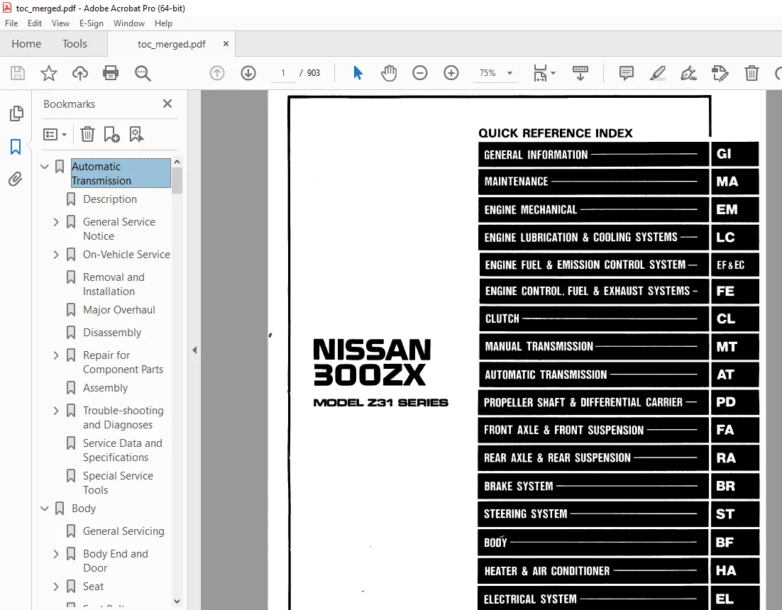
1986 NISSAN 300ZX Z31 Series Service Manual PDF DOWNLOAD
Automatic Transmission 3
Description 4
General Service Notice 6
Repair Notes 6
Control Valve 6
Lockup Control Valve and O D Cancel Valve 7
Oil Channel 8
Mechanical Operation 9
Hydraulic Control Circuits 10
On-Vehicle Service 11
Control Valve 11
Extension Oil Seal 12
Parking Component 12
Governor Valve Assembly 13
Inhibitor Switch Adjustment 13
Manual Linkage Adjustment 14
Vacuum Diaphragm Rod Adjustment 15
Downshift Solenoid 15
Kickdown Switch Adjustment 16
Overdrive and Lockup Control 17
Removal and Installation 18
Major Overhaul 20
Disassembly 22
Repair for Component Parts 28
Oil Pump 28
Drum Support 30
Control Valve Body 34
Oil Distributor 38
Direct Clutch 39
Front Clutch 42
Rear Clutch (Forward) 45
Low & Reverse Brake 46
Brake Band and Band Servo 47
Governor 48
Accumulator 48
Planetary Carrier 49
Connecting Drum Assembly 49
O D One-Way Clutch 50
Assembly 51
Trouble-shooting and Diagnoses 65
Preliminary Checks 65
Road Testing 65
Road Test Symptom Chart 70
Trouble-Shooting Chart 71
Electrical System/Schematic 74
Electrical System/Wiring Diagram 75
Inspection of A/T Control Unit 76
Inspection of Lockup Control 78
Inspection of O D Control 80
Inspection of Parts related to ASCD 81
Inspection of Kickdown Control 83
Self Diagnostics 84
Pressure Testing 86
Stall Testing 88
Service Data and Specifications 90
Special Service Tools 94
Body 95
General Servicing 96
Body End and Door 100
Front End 100
Rear End 102
Back Door and Fuel Filler Lid Opener 103
Front Door 104
Power Window Wiring 105
Power Door Lock Wiring 106
Seat 107
Manual Driver Seat 107
Semi-Power Driver Seat 108
Full Power Driver Seat 112
Front Assist Seat 116
Rear Seat 117
Seat Belt 118
Instrument 119
Interior and Exterior 120
Inside Trim 120
Exterior 122
Windshield and Windows 126
Windshield 126
Back Door Window 128
Side Window 129
Repairing Leaks 130
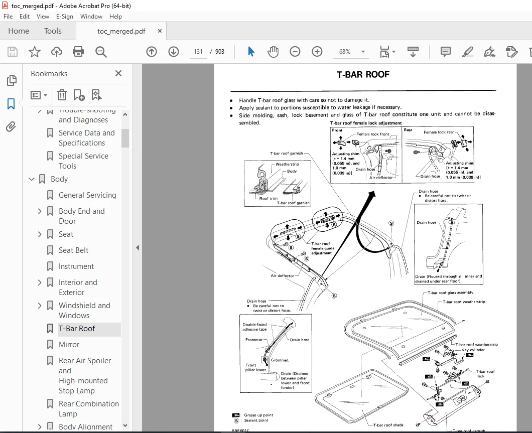
T-Bar Roof 131
Mirror 132
Rear Air Spoiler and High-mounted Stop Lamp 133
Rear Combination Lamp 134
Body Alignment 135
Engine Compartment 135
Underbody 138
Brake System 142
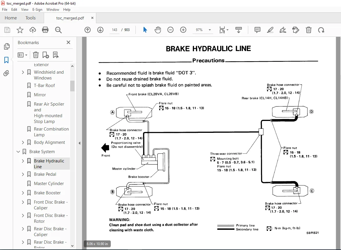
Brake Hydraulic Line 143
Precautions 143
Bleeding Procedure 143
Removal and Installation 144
Inspection 144
Brake Pedal 145
Inspection 145
Adjustment 146
Master Cylinder 147
Brake Booster 148
Operating Check 148
Airtight Check 148
Removal and Installation 148
Inspection 149
Front Disc Brake – Caliper 150
Pad Replacement 150
Removal and Installation 151
Disassembly 151
Inspection 151
Assembly 151
Front Disc Brake – Rotor 152
Inspection 152
Rear Disc Brake – Caliper 153
Pad Replacement 154
Removal and Installation 154
Disassembly 155
Inspection 156
Assembly 156
Rear Disc Brake – Rotor 157
Inspection 157
Parking Brake 158
Removal 158
Inspection 158
Adjustment 159
Service Data and Specifications 160
General Specifications 160
Inspection and Adjustment 160
Tightening Torque 161
Special Service Tool 162
Clutch 164
Hydraulic Clutch Control 165
Precautions 165
Bleeding Procedure 166
Adjusting Clutch Pedal 166
Clutch Master Cylinder 167
Operating Cylinder 168
Clutch Damper 168
Clutch Control – Release Bearing 169
Clutch Unit 170
Service Data and Specifications 173
Special Service Tools 175
Engine Fuel & Emission Control System 176
Precautions 177
Component Parts Location 178
ECCS Diagram 179
Non-Turbo 179
Turbo 180
ECCS Chart 181
Non-Turbo 181
Turbo 182
ECCS Wiring Diagram 183
Fuel Flow System Description 185
Air Flow System Description 186
Vacuum Control Valve 187
Turbocharger 187
Emergency Relief Valve 187
ECCS Component Description 188
Control Unit 188
Crank Angle Sensor 188
Air Flow Meter 189
Head Temp Sensor 190
Exhaust Gas Sensor 190
Throttle Valve Switch 191
Vehicle Speed Sensor 191
Fuel Temp Sensor 192
Detonation Sensor 192
Fuel Injector 192
Power Transistor 193
Ignition Coil 193
Idle-Up Solenoid Valve 193
EGR Control Valve 194
EGR Control Solenoid Valve 194
Fuel Pump 194
Air Regulator 195
Air Injection Valve 195
AIV Control Solenoid Valve 195
Pressure Regulator Control Solenoid Valve 196
ECCS System Description 197
Fuel Injection Control 197
Ignition Timing Control 200
Idle-Up Control (Non-Turbo) 201
Idle Speed Control (Turbo) 202
Exhaust Gas Recirculation Control 203
Fuel Pump Control 204
Air Injection Valve Control 205
Pressure Regulator Control 206
Air Regulator Control 207
Exhaust Gas Sensor Heater Control 207
Air Flow Meter Self Cleaning Control 208
Fail Safe System 209
Diagnostic Procedure 210
Caution 210
Tips on Diagnoses 210
Driveability 211
Improper Idling and Stall 213
Engine Startability 214
Idle Speed and Ignition Timing Inspection 215
Idle Mixture Ratio Inspection 218
Self Diagnoses 219
Electronic Control System Inspection 225
Crank Angle Sensor 225
Air Flow Meter 228
Cylinder Head Temperature Sensor 231
Vehicle Speed Sensor 233
Ignition Signal 234
Fuel Pump 237
Throttle Valve Switch 238
Neutral Switch 240
Load Signal 242
Air Conditioner Signal 243
Start Signal 244
Detonation Sensor 245
Fuel Temperature Sensor 246
Injector 248
Battery Voltage and Ground Test 250
Air Regulator 252
EGR Control System 254
Exhaust Gas Sensor 257
Auxiliary Air Control Valve or Idle-Up Solenoid Valve 259
Self Cleaning Hot Wire 260
Pressure Regulator Control Solenoid Valve 261
Air Injection Valve Control System 264
Mixture Ratio Feedback System Inspection 267
Fuel System Inspection 270
Releasing Fuel Pressure 270
Fuel Pressure Check 270
Injector Removal and Installation 272
Turbocharger 273
Injector Cooling Fan 276
Crankcase Emission Control System 280
Exhaust Emission Control System 281
Evaporative Emission Control System 282
Service Data and Specifications 284
Electrical System 285
How to read Diagrams 286
Standardized Relay 289
Power Supply Routing 290
Battery 293
How To Handle Battery 293
Specific Gravity Check 295
Battery Test and Charging Chart 296
Starting System 301
Starter 302
Construction 302
Magnetic Switch Check 303
Pinion/Clutch Check 303
Brush Check 304
Field Coil Check 304
Armature Check 305
Assembly 306
Service Data and Specifications 306
Charging System 307
Wiring Diagram – Turbo 307
Wiring Diagram – Non-Turbo 308
Trouble Shooting 309
Alternator 310
Construction (Mitsubishi) 310
Construction (Hitachi) 310
Removal 311
Disassembly 311
Rotor Slip Ring Check 311
Brush Check 312
Stator Check 312
Diode Check 313
Assembly 314
Service Data and Specifications 315
Combination Switch 316
Check 316
Replacement 317
Instrument Switch 318
Headlamp 319
Schematic 319
Wiring Diagram 320
Operation 324
Description 325
Trouble Shooting 333
Removal 334
Installation 335
Adjustment 335
Headlamp Motor Check 336
Aiming Adjustment 336
Exterior Lamp 337
Clearance, License, Tail, & Stop lamps Wiring Diagram 337
Auxiliary Driving Lamp Wiring Diagram 339
Back-up lamp Wiring Diagram 339
Turn Signal & Hazard Warning lamps Wiring Diagram 340
Stop and Tail lamp Sensor Check 341
Bulb Specifications 341
Interior Lamp 342
Needle Type Combo Meter (SF & GL) 342
Digital Combo Meter (GLL) 343
Interior, Luggage and Step lamps 344
Illuminated Entry/Door Key 347
Meter and Gauges 349
Digital Combo Meter 349
Schematic 351
Wiring Diagram 352
Display Check 354
Preparation for Trouble Shooting 355
Trouble Shooting 355
Power Unit Check 361
Boost Sensor Check 361
Speed Sensor Signal Check 362
Fuel Tank Gauge Check 364
Water Temp Sensor Check 364
Oil Pressure Sensor Check 364
Digital Combo Gauge 365
Schematic 365
Wiring Diagram 366
Trouble Shooting 367
Direction Sensor Amplifier Check 371
Compass Input Check 371
Direction Sensor Check 372
Direction Sensor Installation 372
Needle Type Combo Meter 373
Tacho, Fuel & Water Temp Gauges 374
Fuel Tank Gauge Check 375
Speed Sensor Signal Check 375
Speedometer Cable Removal 375
Needle Type Combo Gauge 376
Oil Temp Sensor Check 377
Boost Gauge Trimmer Adjustment 377
Oil Temp, Oil Pressure, Boost & Volt Gauges 378
Warning Lamp and Chimes 379
Schematic 379
Warning lamp Wiring Diagram – Digital Combo Meter 380
Turbo 380
Non-Turbo 381
Warning lamp Wiring Diagram – Needle Type Combo Meter 382
Turbo 382
Non-Turbo 383
SF Model 384
Warning Chime Wiring Diagram 385
SF Model 385
GL & GLL Models 386
Diode Check 387
Warning Chime Check 387
Voice Warning System 388
Schematic 388
Wiring Diagram 389
Needle Type Combo Meter 389
Digital Type Combo Meter 390
Operational Check 391
Trouble Shooting 392
Time Control System 394
Schematic 394
Wiring Diagram 395
SF Model 395
GL & GLL Models 396
Preparation for Trouble Shooting 397
Power Supply Circuit Check 397
Trouble Shooting 397
Wiper and Washer 403
Wiring Diagram 403
Installation 403
Washer Nozzle Adjustment 404
Rear Wiper/Washer Wiring Diagram 405
Headlamp Washer Wiring Diagram 406
Horn, Cigarette Lighter, Clock 407
Rear Window Defogger 408
Wiring Diagram 408
Filament Check 409
Filament Repair 409
Audio and Power Antenna 411
Wiring Diagram 411
SF & GL Models 411
GLL Model 412
Power Antenna Motor Check 413
Radio Fuse Check 413
Automatic Speed Control Device 414
Schematic 414
Wiring Diagram 415
Needle Type Combo Meter 415
Digital Combo Meter 416
Preparation for Trouble Shooting 417
Trouble Shooting 417
ASCD Actuator Check 420
ASCD Wire Adjustment 421
Steering Wheel Switch System 422
Description 422
Removal and Installation 426
Schematic 429
Wiring Diagram 430
Trouble Shooting 432
Receiver Check 438
Head Amplifier Check 439
Slip Ring Check 439
Transmitter Check 440
Steering Wheel Switch Check 441
ASCD Control Unit Check 442
Radio Check 442
Theft Warning System 444
Location of Electrical Units 444
Operation of Switches and Sensors 444
Schematic 446
Wiring Diagram 448
Trouble Shooting 450
IND-1 451
IND-2 452
IND-3 453
IND-4 454
IND-5 455
IND-6 456
IND-7 456
ARM-1 457
ARM-2 457
ARM-3 458
ARM-4 458
ALR-1 459
ALR-2 460
ALR-3 461
ALR-4 461
ALR-5 462
ALR-6 462
ST-1 463
ST-2 463
Terminal Check 464
Preparation for Check 466
A 466
B 466
C 466
D 466
E 467
F 467
G 467
H 467
I 467
J 467
K 468
L 468
N 468
O 468
P 468
Z 468
Control Unit Check 469
Preparation for Check 469
a 470
b 470
c 471
d 471
e 471
f 472
g 472
h 473
i 473
j 473
m 474
Adapter Harness Check 474
Location of Electrical Units 475
Harness Layout 477
Outline 477
Main Harness 478
Engine Room Harness 483
EFI Harness 484
Instrument Harness 485
Console Harness 486
Air Conditioner Harness 487
Back Door Harness 488
Engine Mechanical 489
Engine Components (Outer Parts) 490
Compression Pressure 492
Timing Belt 493
Removal 494
Inspection 495
Installation 497
Cylinder Head 501
Removal 502
Disassembly 503
Inspection 504
Assembly 510
Installation 510
Distributor Installation 513
Oil Pan 514
Removal 514
Oil Seal Replacement 515
Camshaft Oil Seal 515
Valve Oil Seal 515
Engine Removal 516
Engine Overhaul 517
Cylinder Block, Crankshaft & Piston 517
Disassembly 518
Inspection 518
Assembly 523
Service Data and Specifications 526
General Specifications 526
Inspection and Adjustment 526
Tightening Torque 533
Special Service Tools 534
Front Axle & Front Suspension 536
Front Axle and Front Suspension 537
Front Axle – Wheel Hub 538
Removal 539
Inspection 539
Installation 539
Preload Adjustment 540
Front Suspension 541
Spring and Strut Assembly 542
Removal and Installation 542
Disassembly 542
Inspection 543
Assembly 544
Tension Rod and Stabilizer Bar 546
Transverse Link 547
Removal and Installation 547
Inspection 548
Suspension Crossmember 549
Adjustable Shock Absorber 550
Removal and Installation 550
Disassembly 551
Inspection 551
Assembly 551
Harness Description 553
Electrical Circuit 553
Trouble Diagnoses 555
Service Data and Specifications 558
General Specifications 558
Inspection and Adjustment 559
Tightening Torque 559
Special Service Tools 560
Engine Control, Fuel & Exhaust Systems 561
Engine Control System 562
Fuel System 563
Removal of Fuel Tank 564
Removal of Fuel Gauge Unit 564
Removal of Electric Fuel Pump 564
Exhaust System 566
Cautions 565
General Information 567
Precautions 568
General 568
For Catalyst 569
For EFI or ECCS Engine 570
For Turbocharger 570
How to use this Manual 571
Identification Information 574
Model Variation 574
Identification Number 576
Dimensions 578
Recommended Fuel and Lubricants 579
Lifting and Towing Points 581
Pantograph Jack 581
Garage Jack and Safety Stand 581
2 point Lift 582
Towing 583
Tightening Torque of Standard Bolt 584
Heater & Air Conditioner 585
General Description 586
Air Flow and Component Layout (Manual) 587
Air Flow 587
Component Layout 588
Location of Vacuum Components 589
Control 590
Heater Electrical Circuit 591
Schematic 591
Wiring Diagram 592
Description – A/C (Manual) 593
Refrigeration Cycle 593
Refrigerant Leak Warning System 594
Discharging, Evacuating, Charging and Checking 596
Precautions 596
Discharging 596
Evacuating the System 597
Charging 597
Checking Refrigerant Level 600
Checking Refrigerant Leaks 601
A/C Performance Test (Manual) 602
Precautions for Refrigerant Connection 604
Piping, Compressor, Mounting and FICD 605
Refrigerant Lines 605
Compressor Mounting 605
Idle Speed Adjusting and Checking 606
Compressor Oil (MJS170) 607
Compressor (MJS170) 609
Leak Test 610
Clutch Replacement 610
Shaft Seal Replacement 611
Valve Replacement 612
A/C Electrical Circuit (Manual) 614
Schematic 614
Wiring Diagram 615
A/C Electrical Components (Manual) 616
Location of A/C Electrical Components (Manual) 618
Trouble Diagnoses (Manual) 619
Circuit for Trouble Diagnoses 620
Preliminary Check 621
1 621
2 622
3 623
4 624
Trouble Diagnoses from Abnormal Conditions 625
A 625
B 626
C 627
D 628
E 630
F 632
G 634
H 636
I 637
J 639
K 642
L 642
M 643
N 645
P 645
Q 646
R 649
S 650
Description – A/C (Auto) 651
Features 651
Refrigerant Cycle 652
Function of Switches on Control Unit 653
Basic Control Function and Control Switches 654
Display of the Air Flow Indicator 655
Display of Temperature Setting 655
Control System 656
System Operation 657
Air Mix Door Control 657
Intake Door Control 662
Outlet Door Control 663
Air Flow Volume Control 665
Control at Starting 667
Compressor, Water Cock Control & compensation for Ambient Temperature 668
Function of Set TEMP Adjuster 669
Function of Self Diagnoses of Trouble 670
Air Flow and Component Layout (Auto) 671
Air Flow 671
Component Layout 672
Location of Vacuum Components (Auto) 673
A/C Performance Test (Auto) 674
A/C Performance Test / Piping (Auto) 675
A/C Electrical Circuit (Auto) 676
Schematic 676
Wiring Diagram 678
A/C Electrical Components (Auto) 680
Location of A/C Electrical Components (Auto) 681
Diagnostic Procedure 682
Self Diagnosing System of Trouble (Auto) 684
Inspection 684
Input System 684
Ambient Temperature Sensor 685
Output System 685
Trouble Diagnoses (Auto) 687
Circuit for Trouble Diagnoses 689
Auto A/C System Diagnoses 692
Input System Diagnoses 694
Output System Diagnoses 696
Automatic Amplifier Diagnoses 704
Replacement of Control and Switch Panel Assy 707
Fault Location 708
Service Data and Specifications 719
General Specifications 719
Inspection and Adjustment 719
Tightening Torque 720
Special Service Tools 722
Engine Lubrication & Cooling Systems 723
Engine Lubrication System (Non-Turbo) 724
Lubrication Circuit 724
Oil Pressure Check 725
Oil Pump Disassembly and Assembly 726
Oil Pump Inspection 727
Oil Pressure Relief Valve Inspection 727
Engine Lubrication System (Turbo) 728
Removal and Installation 728
Cooling System (Non-Turbo) 729
Cooling Circuit 729
Checking Cooling System 730
Water Pump Removal and Installation 731
Water Pump Inspection 731
Thermostat Description 732
Thermostat Removal and Installation 732
Thermostat Inspection 733
Radiator Removal and Installation 733
Cooling Fan Disassembly and Assembly 734
Cooling Fan Inspection 734
Cooling System (Turbo) 735
Electric Cooling Fan Removal and Installation 735
Water Temperature Switch Inspection 735
Coolant Delivery System Removal and Installation 736
Service Data and Specifications 737
Engine Lubrication System 737
Engine Cooling System 738
Special Service Tools 739
Maintenance 740
Periodic Maintenance 741
Normal Driving Conditions 741
Severe Driving Conditions 742
General Maintenance 743
Lubrication Chart 746
Engine Maintenance 747
Checking Drive Belts 747
Replacing Air Cleaner Filter 747
Checking Vapor Lines 747
Checking Fuel System 748
Replacing Fuel Filter 748
Changing Engine Coolant 749
Changing Engine Oil and Oil Filter 751
Checking and Replacing Spark Plugs 752
Checking Ignition Wires 753
Checking Idle Speed (VG30E) 754
Checking Exhaust Gas Sensor 755
Replacing Timing Belt 757
Chassis and Body Maintenance 761
Checking Exhaust System 761
Checking Clutch Operation 761
Checking Clutch Fluid Level 761
Changing Clutch Fluid 761
Checking Clutch System 762
Checking M/T Oil 762
Changing M/T Oil 762
Checking A/T Fluid 763
Changing A/T Fluid 764
Checking Propeller Shaft 764
Checking Differential Gear Oil 764
Changing Differential Gear Oil 764
Checking Front Axle and Front Suspension Parts 765
Checking Steering Linkage 765
Checking Front Wheel Bearing Grease 766
Checking Rear Axle and Rear Suspension Parts 766
Checking Drive Shaft 767
Checking Front Wheel Alignment 767
Checking Rear Wheel Alignment 769
Checking Brake Fluid Level and Leaks 770
Checking Brake Lines & Hoses 770
Checking Disc Brake 771
Checking Foot Brake Pedal Operation 771
Checking Parking Brake 772
Checking Tire Condition 772
Tire Rotation 773
Tire Replacement 774
Wheel Nut 775
Tire Repair 775
Wheel Inspection 775
Balancing Wheels 776
Spare Tire 776
Checking Steering Gear and Linkage 778
Checking Power Steering System Fluid and Lines 778
Body 779
Service Data and Specifications 780
Engine Maintenance 780
Chassis and Body Maintenance 780
Special Service Tools 782
Manual Transmission 783
Removal and Installation 784
On Vehicle Service 785
Model FS5W71C 786
Major Overhaul 786
Case Components 786
Gear Components 787
Shift Control Components 788
Disassembly 789
Repair for Component Parts 790
Forks and Fork Rods 790
Gears and Shafts 790
Oil Seals 798
Adapter Plate 798
Assembly 800
Model BW T-5 (FS5R90A) 802
Case, Shift Cover, Extension Housing 802
Input Shaft Assembly 803
Output Shaft Assembly 803
Countershaft Assembly 804
Reverse Idler Assembly 804
Rear Extension 805
Case Cover 805
Transmission Case 806
Gears & Shafts 809
Replacement of Oil Seals 810
Replacement of Bearings 811
Service Data and Specifications 812
General Specifications 812
Inspection and Adjustment 813
Tightening Torque 814
Special Service Tools 815
Propeller Shaft and Differential Carrier 817
Propeller Shaft 818
General Inspection 818
Removal and Installation 819
Inspection 819
Final Drive 820
On Vehicle Service 821
Front Oil Seal Replacement 821
Side Oil Seal Replacement 822
Ring Gear to Drive Pinion Backlash 822
Removal and Installation 823
Dissasembly 824
Pre-Inspection 824
Differential Carrier 825
Differential Case 827
Inspection 829
Ring Gear and Drive Pinion 829
Differential Case Assembly 829
Bearing 829
Adjustment 830
Setting up Each Tool 830
Drive Pinion Height 831
Drive Pinion Preload 833
Side Bearing Preload 834
Tooth Contact 839
Assembly 840
Differential Case 840
Differential Carrier 841
Service Data and Specifications 846
Propeller Shaft 846
Differential Carrier 846
Special Service Tools 848
Rear Axle & Rear Suspension 850
Rear Axle and Rear Suspension 851
Removal and Installation 852
Rear Axle – Axle Shaft 853
Removal 853
Inspection 853
Installation 854
Drive Shaft 855
Drive Shaft – Tripod-Tripod Type 856
Disassembly 856
Inspection 858
Assembly 858
Drive Shaft – Double Offset-Birfield Type 861
Disassembly 861
Inspection 862
Assembly 862
Rear Suspension 864
Stabilizer Bar 865
Shock Absorber (Non-Adjustable Type) 865
Coil Spring 866
Suspension Arm 866
Suspension Member and Diff Mounting Insulator 867
Rear Suspension – Adjustable Shock Absorber 869
Removal and Installation 869
Inspection 870
Assembly 870
Trouble Diagnoses 870
Service Data and Specifications 871
General Specifications 871
Inspection and Adjustment 872
Tightening Torque 873
Special Service Tools 874
Steering System 875
Steering System 876
Steering Column 878
Non-Tilt Type Column 878
Tilt Type Column 879
Power Steering System 880
Checking 880
Fluid Level Check 880
Power Steering Pump Belt Tension 880
Fluid Leakage Check 880
Bleeding Hydraulic System 880
Hydraulic System Check 880
Turning Force Check 881
Steering Wheel Play Adjustment 881
Power Steering Gear and Linkage 882
Disassembly and Assembly 882
Inspection and Adjustment 886
Power Steering Oil Pump 888
Pre-Disassembly Inspection 888
Oil Pump Installation 888
Disassembly 889
Inspection 890
Assembly 890
Wiring Diagram – Oil Pressure Switch 891
Service Data and Specifications 892
General Specifications 892
Inspection and Adjustment 892
Tightening Torque 893
Special Service Tools 895
Circuit Diagram (GL & SF) 900
Need help? Contact: [email protected]
https://vimeo.com/849843840?share=copy
DESCRIPTION:
1986 NISSAN 300ZX Z31 Series Service Manual PDF DOWNLOAD
FOREWORD
- This manual contains maintenance and repair procedures for the 1986 Nissan 300ZX. In order to assure your safety and the efficient functioning of the vehicle, this manual should be read thoroughly.
- It is especially important that the PRECAUTIONS in the GI section be completely understood before starting any repair task.
- All information in this manual is based on the latest product information at the time of publication. The right is reserved to make changes in specifications and methods at any time without notice
GENERAL SERVICE NOTICE:
• Before proceeding with disassembly, thoroughly clean the outside of the transmission. It is important to prevent the internal parts of the transmission from becoming contaminated by dirt or other foreign matter.
• Disassembly should be done in a clean work area.
• Use a nylon cloth or paper towel for wiping parts clean. Common shop rags can leave lint that might interfere with the transmission’s operation.
• When disassembling parts, be sure to place them in order in parts rack so they can be put back in the unit in their proper positions.
• All parts should be carefully cleaned with a general purpose, non-flammable solvent before inspection or reassembly.
• Gaskets, seals, and 0-rings should be replaced. It is also very important to perform functional tests whenever it is designated.
• The valve body contains many precision parts and requires extreme care when parts are removed and serviced. Place removed parts on a parts rack so they can be put back in the valve body in the same positions and sequences. Care will also prevent springs and small parts from becoming scattered or lost.
• Before assembly, apply a coat of recommended A.T.F. to all parts. Vaseline may be applied to 0-rings and seals. Do not use any grease.
PLEASE NOTE:
- This is the same manual used by the dealers to diagnose and troubleshoot your vehicle
- You will be directed to the download page as soon as the purchase is completed. The whole payment and downloading process will take anywhere between 2-5 minutes
- Need any other service / repair / parts manual, please feel free to contact [email protected] . We still have 50,000 manuals unlisted
G.P