Trusted Business
Verified & Licensed
Virus Free Files
100% Safe Downloads
Secure Payment
SSL Protected
Instant Delivery
Available Immediately
1988 NISSAN 300ZX Z31 Series Service Manual PDF DOWNLOAD
$34.95
1988 NISSAN 300ZX Z31 Series Service Manual PDF DOWNLOAD
Instant PDF Download
Available immediately
Save to Your Device
Download & keep forever
Antivirus Scanned
100% virus-free
Trusted Worldwide
175,000+ customers
Description
1988 NISSAN 300ZX Z31 Series Service Manual PDF DOWNLOAD
FILE DETAILS:
1988 NISSAN 300ZX Z31 Series Service Manual PDF DOWNLOAD
Language : English
Pages : 985
Downloadable :Yes
File Type : PDF
IMAGES PREVIEW OF THE MANUAL:
TABLE OF CONTENTS:
1988 NISSAN 300ZX Z31 Series Service Manual PDF DOWNLOAD
HOW TO USE THIS MANUAL GI 15
IDENTIFICATION INFORMATION 8
DESCRIPTION OF E4N71B 20
GENERAL SERVICE NOTICE 22
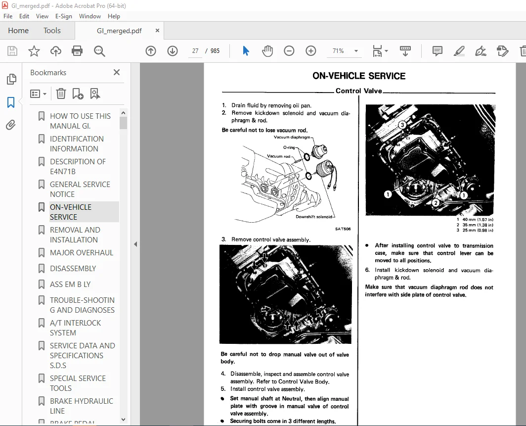
ON-VEHICLE SERVICE 27
REMOVAL AND INSTALLATION 34
MAJOR OVERHAUL 36
DISASSEMBLY 38
ASS EM B LY 67
TROUBLE-SHOOTING AND DIAGNOSES 82
A/T INTERLOCK SYSTEM 107
SERVICE DATA AND SPECIFICATIONS S D S 113
SPECIAL SERVICE TOOLS 117
BRAKE HYDRAULIC LINE 170
BRAKE PEDAL 172
BRAKE BOOSTER 175
FRONT DISC BRAKE CL28VE, CL2BVB) – Caliper 177
Rotor 180
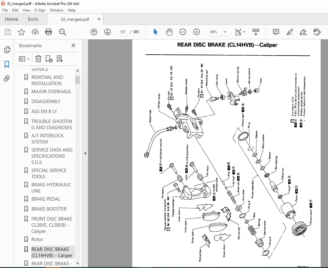
REAR DISC BRAKE (CL14HVB) – Caliper 181
REAR DISC BRAKE – Rotor 185
PARKING BRAKE 186
DATA AND SPECIFICATIONS S D S ) 188
SPECIAL SERVICE TOOL 190
HYDRAULIC CLUTCH CONTROL 192
CLUTCH CONTROL Release Bearing 196
CLUTCH UNIT 197
SPECIAL SERVICE TOOLS 202
PRECAUTIONS EF & 205
ENGINE AND EMISSION CONTROL PARTS LOCATION EF & 206
E C C S DIAGRAM EF & 207
FUEL FLOW SYSTEM DESCRIPTION EF & 211
AIR FLOW SYSTEM DESCRIPTION EF & 212
E C C S CIRCUIT DIAGRAM EF & 213
E C C S WIRING DIAGRAM EF & 214
E C C S DESCRIPTION EF & 216
SELF DIAGNOSIS EF & 263
ELECTRONIC CONTROL SYSTEM INSPECTION EF & 284
CRANK ANGLE SENSOR EF & 286
FLOW METER EF & 288
CYLINDER HEAD TEMPERATURE SENSOR EF & 290
VEHICLE SPEED SENSOR EF & 292
IGNITION SIGNAL EF & 294
FUEL PUMP EF & 296
ENGINE CONTROL UNIT EF & 300
E G R FUNCTION EF & 302
EXHAUST GAS SENSOR EF & 306
FUEL TEMPERATURE SENSOR EF & 314
THROTTLE SENSOR EF & 316
INJECTOR LEAK EF & 318
A I V CONTROL SOLENOID VALVE EF & 326
E G R CONTROL SOLENOID VALVE EF & 328
VALVE EF & 330
VALVE EF & 332
SWITCH EF & 334
P R CONTROL SOLENOID VALVE EF & 336
REGULATOR EF & 338
E C U INPUT/OUTPUT SIGNAL INSPECTION EF & 340
MIXTURE RATIO FEEDBACK SYSTEM INSPECTION EF & 345
INSPECTION EF & 350
TURBOCHARGER INSPECTION EF & 353
EVAPORATIVE EMISSION CONTROL SYSTEM EF & 355
E G R SYSTEM INSPECTION EF & 357
CRANKCASE EMISSION CONTROL SYSTEM EF & 358
A I V SYSTEM INSPECTION EF & 359
SERVICE DATA AND SPECIFICATIONS S D S ) EF & 361
EF & 204
Impossible to start – no combustion EF & 238
Impossible to start – partial combustion EF & 239
Impossible to start – partial combustion (not affected by throttle position) EF & 240
combustion quality) EF & 241
5 Hard to start – before warm-up EF & 242
– after warm-up EF & 243
– morning after a rainy day EF & 245
– no fast idle EF & 246
– low idle (afterwarm-up) EF & 247
– high idle (after warm-up) EF & 248
– before warm-up EF & 249
– afterwarm-up EF & 250
– stumble (while accelerating) EF & 251
– surge (while cruising) EF & 252
– lack of power EF & 253
– during start-up EF & 255
– while idling EF & 256
– while accelerating EF & 257
– whilecruising EF & 258
– while decelerating/just after stopping EF & 259
– while loading (power steering air conditioner headlamps etc EF & 260
– through the intake EF & 261
– through the exhaust EF & 262
EF %t 237
HARNESS CONNECTOR 363
STANDARDIZED RELAY 364
POWER SUPPLY ROUTING 366
BATTERY 370
STARTING SYSTEM 378
STARTING SYSTEM Starter 379
CHARGING SYSTEM 384
CHARGING SYSTEM -Alternator 387
COMBINATION SWITCH 393
INSTRUMENT SWITCH 395
HEADLAMP 396
EXTERIOR LAMP 415
INTERIOR LAMP 420
METER AND GAUGES Digital Type Combination Meter 426
METER AND GAUGES Needle Type Combination Meter 444
METER AND GAUGES Needle Type Combination Gauge 447
WARNING LAMPS AND CHIME 451
TIME CONTROL SYSTEM 459
WIPER AND WASHER 468
HORN CIGARETTE LIGHTER CLOCK 472
REAR WINDOW DEFOGGER 473
AUDIO AND POWER ANTENNA 476
AUTOMATIC SPEED CONTROL DEVICE A S C D ) 479
STEERING WHEEL SWITCH SYSTEM 487
THEFT WARNING SYSTEM 507
LOCATION OF ELECTRICAL UNITS 538
HARNESS LAYOUT 541
SPECIAL SERVICE TOOLS 556
PREPARATION 559
IVG30E 558
ENGINE COMPONENTS Outer Parts 562
CHECKING COMPRESSION PRESSURE 564
TIMING BELT 565
TIMING BELT Removal 566
TIMING BELT Inspection 567
TIMING BELT Installation 568
CYLINDER HEAD 571
CYLINDER HEAD Removal 572
HEAD Disassembly 574
CYLINDER HEAD Inspection 574
HEAD Assembly 581
HEAD Installation 582
OIL PAN 585
OIL SEAL REPLACEMENT 588
ENGINE REMOVAL 590
ENGINE OVERHAUL 592
ENGINE OVERHAUL Disassembly 593
FRONT AXLE AND FRONT SUSPENSION 613
FRONT AXLE Wheel Hub 614
FRONT SUSPENSION 617
FRONT SUSPENSION -Spring and Strut Assembly 618
FRONT SUSPENSION -Tension Rod and Stabilizer Bar 622
FRONT SUSPENSION -Transverse Link 623
FRONT SUSPENSION – Suspension Crossrnember 625
(Including wiring diagram) 626
SERVICE DATA AND SPECIFICATIONS S D S ) 635
SPECIAL SERVICE TOOLS 637
GENERAL DESCRIPTION 645
AIR FLOW AND COMPONENT LAYOUT (Manual) 646
LOCATION OF VACUUM COMPONENTS (Manual) 648
CONTROL 649
HEATER ELECTRICAL CIRCUIT 650
DESCRIPTION Air Conditioner (Manual) 652
DISCHARGING EVACUATING CHARGING AND CHECKING 653
A/C PERFORMANCE TEST (Manual) 659
REFRIGERANT CONNECTION 661
F 1 C D 662
COMPRESSOR OIL- ForMJS170 664
COMPRESSOR -Model MJS170 666
A/C ELECTRICAL CIRCUIT (Manual) 671
A/C ELECTRICAL COMPONENTS (Manual) 673
LOCATION OF A/C ELECTRICAL COMPONENTS (Manual) 675
TROUBLE DIAGNOSES (Manual) 676
DESCRIPTION -Air Conditioner (Auto) 708
AIR FLOW AND COMPONENT LAYOUT (Auto) 728
LOCATION OF VACUUM COMPONENTS (Auto) 730
A/C PERFORMANCE TEST (Auto) 731
(Auto) 732
A/C ELECTRICAL CIRCUIT (Auto) 733
A/C ELECTRICAL COMPONENTS (Auto) 737
LOCATION OF A/C ELECTRICAL COMPONENTS (Auto) 738
SELF-DIAGNOSING SYSTEM OF TROUBLE (Auto) 741
TROUBLE DIAGNOSES (Auto) 745
SERVICE DATA AND SPECIFICATIONS S D S ) 774
Circuit for Trouble Diagnoses 677
Preliminary Check 678
1) Insufficient cooling (Mode switch position: “FACE”) 678
2) Insufficient heating 679
Insufficient air flow (Blower motor does not rotate 680
4) Abnormal sound 681
Trouble Diagnoses from Abnormal Conditions 682
(A) Blower motor does not rotate 682
(B) Air flow cannot be changed between HI and LO 683
(C) Blower motor continues to rotate when fan switch is turned off 684
(D) “FACE” mode cannot be set 685
(E) “8/L” mode cannot be set 687
(G) “DEMIST” mode cannot be set 691
(H) “DEF” mode cannot be set 693
(I) Outlet air will not become warm 694
(J) Outlet air will not become cool 696
(K) Outlet air temperature cannot be changed with temp control lever 699
(L) Malfunction of water cock operation 699
(M) Outlet air temperature fluctuates 700
(N) Recirculation mode cannot be set when “REC” switch is pressed 702
(P) Outside air is not drawn into compartment when “REC” switch is turned off 702
(Q) Compressor clutch is not engaged 703
(!?)Malfunction of F I C D 706
(S) Blower motor rotates intermittently 707
Circuit for trouble diagnoses 747
Auto A/C system diagnosis 749
ACC or when engine is running 749
lnputsystemdiagnosis 751
Inoperative input system 751
Output system diagnosis 753
1) lnoperativeair mixdoor 753
(CO) Input & output system: Check 0-1 for proper operation 753
Doors water cock and compressor diagnosis 755
Check if 12 volts are present at terminal 867 (S8) with connector @ in place 755
connected 756
vacuumtank 757
located in engine compartment 758
Blower motor diagnosis 759
Conduct self-diagnostic checks on input & output system 759
Automatic amplifier diagnosis 761
LCD (Liquid Crystal Display) or LED (Light Emitting Diode) does not glow 761
(IO) Do LCD’s or LED’s glow? 761
Operating (Buzzing) sound is not emitted 762
across buzzer terminals (red @ and black 0 ) to see if buzzer sounds 762
Switches on switch panel assembly do not operate 762
Is SET AMB temperature displayed when ignition switch is set to ACC? 762
Erroneous display during inspection of the input system 763
Are all numbers except Step No 7 correct? 763
Erroneous operation during inspection of the output system 763
Does air flow indication change properly? 763
Escutcheon lamp does not come on 763
Replacement of control subassembly and switch panel assembly 764
Blower continues to rotate in HI mode 765
Blower rotates only in LO mode 765
Blower motor does not rotate 766
Blower speed changes variably 766
No air is discharged from vent outlets 767
No air is discharged from floor outlets 767
No air is discharged from defroster outlets 768
Hot air is not discharged or outlet air temperature does not change 768
No cool air is discharged 769
Cool air at foot level will not stop or is discharged intermittently 770
Outslde air is not drawn into compartment 770
Dischargedairistoocool 771
Discharged air is not cool 771
Compartment istoohot 772
ENGINE LUBRICATION SYSTEM 779
LUBRICATION SYSTEM – For Turbocharged Models 783
ENGINE COOLING SYSTEM 784
ENGINE COOLING SYSTEM – For Tuhocharged Models 790
SERVICE DATA AND SPECIFICATIONS S D S ) 792
SPECIAL SERVICE TOOLS 794
PERIODIC MAINTENANCE 796
GENERAL MAINTENANCE 798
CHART 801
MAINTENANCE 802
CHASSIS AND BODY MAINTENANCE 810
SPECIFICATIONS S D S ) 829
TOOLS 831
PREPARATION 833
ON-VEHICLE SERVICE 838
REMOVAL AND INSTALLATION 839
MAJOR OVERHAUL 840
DISASSEMBLY 843
INSPECTION 848
ASSEMBLY 850
MAJOR OVERHAUL 862
DISASSEMBLY 866
INSPECTION 873
ASSEMBLY 875
SERVICE DATA AND SPECIFICATIONS S D S ) 887
PROPELLER SHAFT 893
FINAL DRIVE (Model R200) 895
ON-VEHICLE SERVICE (Model R200) 896
REMOVAL AND INSTALLATION (Model R200) 898
DISASSEMBLY (Model R200) 899
INSPECTION (ModelR200) 904
ASSEMBLY (Model R200) 915
LIMITED SLIP DIFFERENTIAL (Model R200) 921
SERVICE DATA AND SPECIFICATIONS S D S ) 929
SPECIAL SERVICE TOOLS 932
REAR AXLE AND REAR SUSPENSION 935
REAR AXLE Axle Shaft 937
DRIVE SHAFT 939
DRIVE SHAFT “Tripod-Tripod” Type 940
DRIVE SHAFT “Double 0ffset Birfield”Type 945
REAR SUSPENSION 948
REAR SUSPENSION Adjustable Shock Absorber 953
DATA AND SPECIFICATIONS S D S ) 955
SPECIAL SERVICE TOOLS 958
Need help? Contact: [email protected]
DESCRIPTION:
1988 NISSAN 300ZX Z31 Series Service Manual PDF DOWNLOAD
1. A QUICK REFERENCE INDEX, a black tab (e.g. lZII ) is provided on the first page. You can quickly find the first page of each section by matching it to the section’s black tab.
2. THE CONTENTS are listed on the first page of each section.
3. THE TITLE is indicated on the upper portion of each page and shows the part or system.
4. THE PAGE NUMBER of each section consists of two letters, which designate the particular section, and a number {e.g. “FA-5”). 5. THE FIRST LARGE ILLUSTRATION of each section is an exploded view (See below) and contains tightening torques, lubrication points and other information necessary to perform repairs. The illustration should be used in reference to the service matters only when ordering parts, refer to the appropriate PARTS CATALOG.
6. THE FOLLOWING SMALL ILLUSTRATION shows the important steps such as inspection,. use of special tools, knacks of work and hidden or tricky steps which are not shown in the previous large illustration. Assembly, inspection and adjustment procedures for the complicated units such as the automatic transaxle or transmission, etc. are presented in a step by step format where necessary.
PLEASE NOTE:
- This is the same manual used by the dealers to diagnose and troubleshoot your vehicle
- You will be directed to the download page as soon as the purchase is completed. The whole payment and downloading process will take anywhere between 2-5 minutes
- Need any other service / repair / parts manual, please feel free to contact [email protected] . We still have 50,000 manuals unlisted
G.P