Trusted Business
Verified & Licensed
Virus Free Files
100% Safe Downloads
Secure Payment
SSL Protected
Instant Delivery
Available Immediately
1994 INFINITI Q45 G50 Series Service Manual PDF DOWNLOAD
$24.95
1994 INFINITI Q45 G50 Series Service Manual PDF DOWNLOAD
Instant PDF Download
Available immediately
Save to Your Device
Download & keep forever
Antivirus Scanned
100% virus-free
Trusted Worldwide
175,000+ customers
Description
1994 INFINITI Q45 G50 Series Service Manual PDF DOWNLOAD
FILE DETAILS:
1994 INFINITI Q45 G50 Series Service Manual PDF DOWNLOAD
Language : English
Pages : 1380
Downloadable : Yes
File Type : PDF
IMAGES PREVIEW OF THE MANUAL:
TABLE OF CONTENTS:
1994 INFINITI Q45 G50 Series Service Manual PDF DOWNLOAD
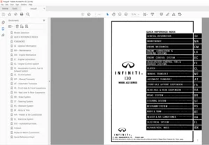
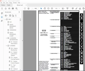
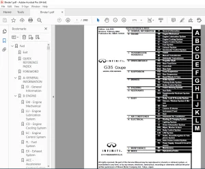
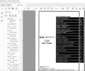
fwd.........................................................................................   1
	Model Selection.........................................................................   0
	QUICK REFERENCE INDEX...................................................................   1
	FOREWORD................................................................................   2
	GI - General Information................................................................   0
	MA - Maintenance........................................................................   0
	EM - Engine Mechanical..................................................................   0
	LC - Engine Lubrication & Cooling System................................................   0
	EF & EC - Engine Fuel & Emission Control System.........................................   0
	FE - Accelerator Control, Fuel & Exhaust Systems........................................   0
	AT - Automatic Transmission.............................................................   0
	PD - Propeller Shaft & Differential Carrier.............................................   0
	FA - Front Axle & Front Suspension......................................................   0
	RA - Rear Axle & Rear Suspension........................................................   0
	BR - Brake System.......................................................................   0
	ST - Steering System....................................................................   0
	BF - Body...............................................................................   0
	HA - Heater & Air Conditioner...........................................................   0
	EL - Electrical System..................................................................   0
	Foldout.................................................................................   0
	Inch to Metric Conversion...............................................................   3
	Quick Reference Chart...................................................................   4
at..........................................................................................   5
	QUICK REFERENCE INDEX...................................................................   0
	TABLE OF CONTENTS.......................................................................   5
	PREPARATION AND PRECAUTIONS.............................................................   6
		Special Service Tools...............................................................   6
		Precautions.........................................................................   7
		Supplemental Restraint System "AIR BAG" and "SEAT BELT PRE-TENSIONER"...............   8
	DESCRIPTION.............................................................................   9
		Cross-sectional View................................................................   9
		Hydraulic Control Circuits..........................................................  10
		Shift Mechanism.....................................................................  11
		Control System......................................................................  13
	TROUBLE DIAGNOSES.......................................................................  15
		Contents............................................................................  15
	TROUBLE DIAGNOSES - A/T Shift Lock System...............................................  95
		Contents............................................................................  95
	ON-VEHICLE SERVICE...................................................................... 110
		Control Valve Assembly and Accumulators Inspection.................................. 110
		Kickdown Switch Adjustment.......................................................... 110
		Revolution Sensor Replacement....................................................... 111
		Rear Oil Seal Replacement........................................................... 111
		Parking Components Inspection....................................................... 111
		Inhibitor Switch Adjustment......................................................... 112
		Manual Control Linkage Adjustment................................................... 112
	REMOVAL AND INSTALLATION................................................................ 113
		Removal............................................................................. 113
		Installation........................................................................ 115
	MAJOR OVERHAUL.......................................................................... 116
		Oil Channel......................................................................... 118
		Locations of Needle Bearings, Thrust Washers and Snap Rings......................... 119
	DISASSEMBLY............................................................................. 120
	REPAIR FOR COMPONENT PARTS.............................................................. 132
		Oil Pump............................................................................ 132
		Control Valve Assembly.............................................................. 136
		Control Valve Upper Body............................................................ 142
		Control Valve Lower Body............................................................ 148
		Reverse Clutch...................................................................... 150
		High Clutch......................................................................... 154
		Forward and Overrun Clutches........................................................ 156
		Low & Reverse Brake................................................................. 160
		Forward Clutch Drum Assembly........................................................ 164
		Rear Internal Gear and Forward Clutch Hub........................................... 166
		Band Servo Piston Assembly.......................................................... 168
		Parking Pawl Components............................................................. 172
	ASSEMBLY................................................................................ 174
		Assembly (1)........................................................................ 174
		Adjustment.......................................................................... 179
		Assembly (2)........................................................................ 183
	SERVICE DATA AND SPECIFICATIONS (SDS)................................................... 193
		General Specifications.............................................................. 193
		Specifications and Adjustment....................................................... 193
bf.......................................................................................... 197
	QUICK REFERENCE INDEX...................................................................   0
	TABLE OF CONTENTS....................................................................... 197
	GENERAL SERVICING....................................................................... 198
		Precautions......................................................................... 198
		Supplemental Restraint System "AIR BAG" and "SEAT BELT PRE-TENSIONER"............... 198
		Circuit Breaker Inspection.......................................................... 198
		Clip Fastener....................................................................... 199
	BODY END................................................................................ 201
		Body Front End...................................................................... 201
		Body Rear End and Opener............................................................ 203
	DOOR.................................................................................... 206
		Front door.......................................................................... 206
		Rear Door........................................................................... 207
	INSTRUMENT PANEL........................................................................ 208
	INTERIOR AND EXTERIOR................................................................... 210
		Interior............................................................................ 210
		Exterior............................................................................ 216
	SEAT.................................................................................... 222
		Front Seat.......................................................................... 222
		Rear Seat........................................................................... 227
	SUN ROOF................................................................................ 228
		Wiring Diagram...................................................................... 229
	WINDSHIELD AND WINDOWS.................................................................. 230
		Windshield and Rear Window.......................................................... 230
		Opera Window........................................................................ 231
	MIRROR AND REAR AIR SPOILER............................................................. 232
		Door Mirror......................................................................... 232
		Rear Air Spoiler.................................................................... 233
	BODY ALIGNMENT.......................................................................... 234
		Engine Compartment.................................................................. 234
		Underbody........................................................................... 236
	SUPPLEMENTAL RESTRAINT SYSTEM (SRS)..................................................... 238
		Precautions for SRS "Air Bag" and "Seat Belt Pre-tensioner" Service................. 238
		Special Service Tools............................................................... 238
		Commercial Service Tools............................................................ 238
		Description......................................................................... 239
		SRS Component Parts Location........................................................ 240
		Caution Labels...................................................................... 241
		Maintenance Items................................................................... 243
		Removal and Installation - Control Unit, Sensors and Seat Belt Pre-tensioner........ 244
		Removal - Air Bag Module and Spiral Cable........................................... 245
		Removal - Front Passenger Air Bag Module............................................ 246
		Installation - Air Bag Module and Spiral Cable...................................... 247
		Installation - Front Passenger Air Bag Module....................................... 249
		Scrapping Air Bag and Seat Belt Pre-tensioners...................................... 249
	TROUBLE DIAGNOSTS - Supplemental Restraint System (SRS)................................. 252
		Contents............................................................................ 252
br.......................................................................................... 264
	QUICK REFERENCE INDEX...................................................................   0
	TABLE OF CONTENTS....................................................................... 264
	PRECAUTIONS AND PREPARATION............................................................. 266
		Precautions......................................................................... 266
		Special Service Tools............................................................... 266
		Commercial Service Tools............................................................ 266
	CHECK AND ADJUSTMENT.................................................................... 267
		Checking Brake Fluid Level.......................................................... 267
		Checking Brake Line................................................................. 267
		Changing Brake Fluid................................................................ 267
		Bleeding Brake System............................................................... 267
	BRAKE HYDRAULIC LINE/CONTROL VALVE...................................................... 268
		Removal............................................................................. 268
		Inspection.......................................................................... 268
		Installation........................................................................ 268
		Proportioning Valve................................................................. 269
	BRAKE PEDAL AND BRACKET................................................................. 270
		Removal and Installation............................................................ 270
		Inspection.......................................................................... 270
		Adjustment.......................................................................... 271
	MASTER CYLINDER......................................................................... 272
		Removal............................................................................. 272
		Disassembly......................................................................... 272
		Inspection.......................................................................... 273
		Assembly............................................................................ 273
		Installation........................................................................ 273
	BRAKE BOOSTER........................................................................... 274
		On-vehicle Service.................................................................. 274
		Removal............................................................................. 274
		Inspection.......................................................................... 274
		Installation........................................................................ 275
	VACUUM PIPING........................................................................... 276
		Removal and Installation............................................................ 276
		Inspection.......................................................................... 276
	FRONT DISC BRAKE........................................................................ 277
		Pad Replacement..................................................................... 277
		Removal............................................................................. 278
		Disassembly......................................................................... 278
		Inspection - Caliper................................................................ 278
		Inspection - Rotor.................................................................. 279
		Assembly............................................................................ 279
		Installation........................................................................ 279
	REAR DISC BRAKE......................................................................... 280
		Pad Replacement..................................................................... 280
		Removal............................................................................. 281
		Disassembly......................................................................... 281
		Inspection - Caliper................................................................ 281
		Inspection - Rotor.................................................................. 282
		Assembly............................................................................ 282
		Installation........................................................................ 282
		Parking Drum Brake.................................................................. 283
	PARKING BRAKE CONTROL................................................................... 286
		Removal and Installation............................................................ 286
		Inspection.......................................................................... 287
		Adjustment.......................................................................... 287
	ANTI-LOCK BRAKE SYSTEM - ABS -.......................................................... 288
		System Components................................................................... 288
		Hydraulic Circuit................................................................... 288
		Wiring Diagram...................................................................... 289
		Removal and Installation............................................................ 290
	TROUBLE DIAGNOSES FOR ABS............................................................... 292
		Contents............................................................................ 292
	TRACTION CONTROL SYSTEM - TCS -......................................................... 313
		Purpose of TCS...................................................................... 313
		System Components................................................................... 314
		Components for TCS Brake System..................................................... 315
		Throttle Valve Control System for TCS............................................... 319
		Engine + Brake TCS System Configuration............................................. 319
		Component........................................................................... 320
		Throttle Memory Function............................................................ 321
		Secondary Throttle Fully-closed Position Self-learning Control...................... 321
		Removal and Installation of TCS Actuator............................................ 322
		Air Bleeding for TCS................................................................ 323
		Removal and Installation of TCS Pump................................................ 323
		Removal and Installation of Rear Wheel Sensor....................................... 324
		Removal and Installation of TCM..................................................... 324
		Removal and Installation of TCS Control Unit........................................ 325
		Removal and Installation of Front Wheel Sensor...................................... 325
		Removal and Installation of ABS Actuator............................................ 325
		Removal and Installation of Throttle Motor.......................................... 325
		Adjustment for Secondary Throttle Position Sensor................................... 326
	TROUBLE DIAGNOSES FOR TCS............................................................... 327
		Contents............................................................................ 327
	SERVICE DATA AND SPECIFICATIONS (S.D.S.)................................................ 379
		General Specifications.............................................................. 379
		Inspection and Adjustment........................................................... 379
ec.......................................................................................... 380
	QUICK REFERENCE INDEX...................................................................   0
	TABLE OF CONTENTS....................................................................... 380
	PREPARATION AND PRECAUTIONS............................................................. 382
		Special Service Tools............................................................... 382
		Supplemental Restraint System "AIR GAG"............................................. 382
		Engine Fuel & Emission Control System............................................... 383
	ENGINE AND EMISSION CONTROL OVERALL SYSTEM.............................................. 384
		ECCS Component Parts Location....................................................... 384
		System Diagram...................................................................... 386
		System Chart........................................................................ 387
		Vacuum Hose Drawing................................................................. 388
		Circuit Diagram..................................................................... 389
	ENGINE AND EMISSION CONTROL PARTS DESCRIPTION........................................... 390
		Engine Control Module (ECM)-ECCS Control Module..................................... 390
		Camshaft Position Sensor (CMPS)..................................................... 390
		Mass Air Flow Sensor (MAFS)......................................................... 390
		Engine Coolant Temperature Sensor (ECTS)............................................ 391
		Throttle Position Sensor (TPS) & Soft/Hard Closed Throttle Position (CTP) Switch.... 391
		Secondary Throttle Position Sensor (TPS) (Models with TCS only)..................... 392
		Fuel Injector....................................................................... 392
		Fuel Pressure Regulator............................................................. 393
		Fuel Pump........................................................................... 393
		Heated Oxygen Sensor (HO2S)......................................................... 393
		Fuel Pump Control Unit.............................................................. 393
		Fuel Damper......................................................................... 394
		Power Transistor Unit & Ignitiion Coil.............................................. 394
		Fast Idle Cam (FIC)................................................................. 394
		Air Cut Valve (Models with TCS only)................................................ 394
		Idle Air Control Valve (IAVC)-Auxiliary Air Control (AAC) Valve..................... 395
		Power Steering Oil Pressure Switch.................................................. 395
		Vehicle Speed Sensor (VSS).......................................................... 395
		Knock Sensor (KS)................................................................... 395
		Exhaust Gas Recirculation (EGR) Valve............................................... 395
		EGR Control (EGRC)-BPT Valve........................................................ 396
		EGR Control (EGRC)-Solenoid Valve................................................... 396
		Canister Control Solenoid Valve..................................................... 396
		Fuel Filter......................................................................... 396
		Data Link Connector for CONSULT..................................................... 396
		EGR Temperature Sensor.............................................................. 397
		Valve Timing Control (VTC) Solenoid Valve........................................... 397
		Carbon Canister..................................................................... 397
	ENGINE AND EMISSION CONTROL SYSTEM DESCRIPTION.......................................... 398
		Multiport Fuel Injection (MFI) System............................................... 398
		Electronic Ignition (EI) System..................................................... 401
		Idle Air Control (IAC) System....................................................... 403
		Fuel Pump Control................................................................... 404
		Exhaust Gas Recirculation (EGR) System.............................................. 405
		Canister Control.................................................................... 405
		Acceleration Cut Control............................................................ 406
		Valve Timing Control (VTC).......................................................... 406
		Heated Oxygen Sensor (HO2S) Heater Control.......................................... 408
		Cooling Fan Control (For U.S.A. models)............................................. 409
		Cooling Fan Control (For Canada models)............................................. 409
		Fail-safe System.................................................................... 410
		Direct Ignition System.............................................................. 412
	IDLE SPEED/IGNITION TIMING/IDLE MIXTURE RATIO INSPECTION................................ 414
	TROUBLE DIAGNOSES....................................................................... 421
		Contents............................................................................ 421
	MULTIPORT FUEL INJECTION SYSTEM INSPECITON.............................................. 607
		Releasing Fuel Pressure............................................................. 607
		Fuel Pressure Check................................................................. 607
		Injector Removal and Installation................................................... 608
	EVAPORATIVE EMISSION SYSTEM............................................................. 609
		Description......................................................................... 609
		Inspection.......................................................................... 609
	CRANKCASE EMISSION CONTROL SYSTEM....................................................... 611
		Description......................................................................... 611
		Inspection.......................................................................... 611
	SERVICE DATA AND SPECIFICATIAONS (SDS).................................................. 612
		General Specifications.............................................................. 612
		Inspection and Adjustment........................................................... 612
el.......................................................................................... 613
	QUICK REFERENCE INDEX...................................................................   0
	TABLE OF CONTENTS....................................................................... 613
	PRECAUTIONS............................................................................. 615
		Supplemental Restraint System "AIR BAG" and "SEAT BELT PRE-TENSIONER"............... 615
	HARNESS CONNECTOR....................................................................... 616
		Description......................................................................... 616
	STANDARDIZED RELAY...................................................................... 617
		Description......................................................................... 617
	POWER SUPPLY ROUTING.................................................................... 620
		Wiring Diagram...................................................................... 620
		Fuse................................................................................ 622
		Fusible Link........................................................................ 622
	BATTERY................................................................................. 623
		How to Handle Battery............................................................... 623
		Service Data and Specifications (SDS)............................................... 625
	STARTING SYSTEM......................................................................... 626
		Construction........................................................................ 626
		Removal and Installation............................................................ 626
		Wiring Diagram...................................................................... 627
		Service Data and Specifications (SDS)............................................... 627
	CHARGING SYSTEM......................................................................... 628
		Construction........................................................................ 628
		Removal and Installation............................................................ 628
		Wiring Diagram...................................................................... 629
		Service Data and Specifications (SDS)............................................... 629
	COMBINATION SWITCH...................................................................... 630
		Combination Switch/Check............................................................ 630
		Steering Switch/Check............................................................... 631
	HEADLAMP................................................................................ 632
		Schematic........................................................................... 632
		Wiring Diagram...................................................................... 633
		Operation (Daytime light system for Canada)......................................... 634
		Schematic........................................................................... 634
		Wiring Diagram...................................................................... 635
		Bulb Replacement.................................................................... 636
		Aiming Adjustment................................................................... 636
		Headlamp Sensor Check............................................................... 637
	EXTERIOR LAMP........................................................................... 638
		Clearance, License, Tail and Stop Lamps/Wiring Diagram.............................. 638
		Back-up Lamp/Wiring Diagram......................................................... 639
		Front Fog Lamp/Wiring Diagram....................................................... 640
		Turn Signal and Hazard Warning Lamps/Wiring Diagram................................. 641
		Fog Lamp Aiming Adjustment.......................................................... 642
		Stop and Tail Lamp Sensor Check..................................................... 642
		Combination Flasher Unit Check...................................................... 642
		Bulb Specifications................................................................. 643
	INTERIOR LAMP........................................................................... 644
		Illumination/Wiring Diagram......................................................... 644
		Interior, Spot, Foot and Trunk Room Lamps/Wiring Diagram............................ 646
		Courtesy Lamp/Wiring Diagram........................................................ 647
		Illumination Control Switch Check................................................... 648
	METER AND GAUGES........................................................................ 649
		Combination Meter................................................................... 649
		Speedometer, Tachometer, Temp. and Fuel Gauges/Wiring Diagram....................... 650
		Inspection/Fuel Gauge and Water Temperature Gauge................................... 651
		Inspection/Vehicle Speed Sensor Signal Circuit...................................... 652
		Inspection/Tachometer............................................................... 653
		Fuel Tank Gauge Unit Check.......................................................... 653
		Fuel Warning Lamp Sensor Check...................................................... 654
		Thermal Transmitter Check........................................................... 654
		Oil Pressure Switch Check........................................................... 654
	WARNING LAMPS AND CHIME................................................................. 655
		Warning Lamps/Schematic............................................................. 655
		Warning Lamps/Wiring Diagram........................................................ 656
		Warning Chime/Wiring Diagram........................................................ 658
		Diode Check......................................................................... 659
		Warning Chime Check................................................................. 659
	DIAGNOSTIC INFORMATION DISPLAY.......................................................... 660
		Description......................................................................... 660
		Self-check.......................................................................... 661
		Wiring Diagram...................................................................... 662
		Trouble Diagnoses................................................................... 664
	LAN - SYSTEM DESCRIPTION................................................................ 673
		System Diagram...................................................................... 673
		Component Parts Location............................................................ 674
		Circuit Diagram..................................................................... 675
		Overall Description................................................................. 683
		Sleep/Wake-up Control............................................................... 685
		Fail-safe System.................................................................... 686
	LAN - TROUBLE DIAGNOSES................................................................. 688
		Work Flow........................................................................... 688
		On-board Diagnosis.................................................................. 689
		On-board Diagnosis - Mode I (LAN communication diagnosis)........................... 690
		On-board Diagnosis - Mode II (Switch monitor)....................................... 693
		On-board Diagnosis - Mode III (Power door lock operation)........................... 695
		On-board Diagnosis - Mode IV (Power window monitor)................................. 697
		On-board Diagnosis - Mode V (Automatic drive positioner operation).................. 699
		Consult............................................................................. 701
		LAN Communication Check............................................................. 704
	POWER WINDOW - LAN...................................................................... 711
		Component Parts and Harness Connector Location...................................... 711
		Wiring Diagram...................................................................... 712
		Schematic........................................................................... 714
		Trouble Diagnoses................................................................... 715
	POWER DOOR LOCK - LAN................................................................... 723
		Component Parts and Harness Connector Location...................................... 723
		Wiring Diagram...................................................................... 724
		Schematic........................................................................... 726
		Trouble Diagnoses................................................................... 727
	AUTOMATIC DRIVE POSITIONER - LAN........................................................ 733
		Component Parts and Harness Connector Location...................................... 733
		Wiring Diagram...................................................................... 734
		Schematic........................................................................... 736
		Trouble Diagnoses................................................................... 737
	POWER SEAT (FRONT RH) - LAN ............................................................ 756
		Wiring Diagram...................................................................... 756
	MULTI-REMOTE CONTROL SYSTEM - LAN....................................................... 757
		Schematic........................................................................... 757
		Wiring Diagram...................................................................... 758
		Trouble Diagnoses................................................................... 760
		Replacing Remote Controller or Control Unit......................................... 763
	DOOR MIRROR - LAN....................................................................... 764
		Wiring Diagram...................................................................... 764
		Trouble Diagnoses................................................................... 765
	TIME CONTROL SYSTEM - LAN............................................................... 771
		Description......................................................................... 771
		Wiring Diagram...................................................................... 772
		Trouble Diagnoses................................................................... 774
	THEFT WARNING SYSTEM - LAN.............................................................. 789
		Component Parts and Harness Connector Location...................................... 789
		Wiring Diagram...................................................................... 790
		Description......................................................................... 792
		Trouble Diagnoses................................................................... 793
	STEP LAMPS - LAN........................................................................ 811
		Wiring Diagram...................................................................... 811
		Trouble Diagnoses................................................................... 812
	ILLUMINATION - LAN...................................................................... 816
	WIPER AND WASHER........................................................................ 817
		Front Wiper and Washer/Wiring Diagram............................................... 817
		Wiper Removal and Installation...................................................... 818
		Wiper Arm Installation.............................................................. 818
		Washer Nozzle Adjustment............................................................ 819
		Wiper Amplifier Check............................................................... 819
	HORN, CIGARETTE LIGHTER, CLOCK.......................................................... 820
		Wiring Diagram...................................................................... 820
	REAR WINDOW DEFOGGER.................................................................... 821
		Wiring Diagram...................................................................... 821
		Filament Check...................................................................... 822
		Filament Repair..................................................................... 823
	TELEPHONE............................................................................... 824
		Telephone/Wiring Diagram............................................................ 824
	AUDIO AND POWER ANTENNA................................................................. 826
		Audio/Wiring Diagram................................................................ 826
		Power Antenna/Wiring Diagram........................................................ 828
		Location of Antenna................................................................. 828
		Antenna Rod Replacement............................................................. 829
		Window Antenna Repair............................................................... 830
	AUTOMATIC SPEED CONTROL DEVICE (ASCD)................................................... 831
		Component Parts and Harness Connector Location...................................... 831
		Wiring Diagram...................................................................... 832
		Trouble Diagnoses................................................................... 834
	LOCATION OF ELECTRICAL UNITS............................................................ 851
		Engine Compartment.................................................................. 851
		Passenger Compartment............................................................... 852
		Luggage Compartment................................................................. 853
		Door................................................................................ 854
	HARNESS LAYOUT.......................................................................... 855
		Outline............................................................................. 855
		Engine Room Harness................................................................. 856
		Main Harness........................................................................ 858
		Body Harness........................................................................ 861
		Tail Harness........................................................................ 862
		Engine Control Harness.............................................................. 864
		Engine Control Sub-harness.......................................................... 866
		Room Lamp Harness................................................................... 868
		Air Bag Harness..................................................................... 868
		Engine Harness...................................................................... 869
		Door Harness (LH side).............................................................. 870
		Door Harness (RH side).............................................................. 871
	SPLICE LOCATION......................................................................... 872
		How to Read Splice Location......................................................... 872
		Engine Room Harness................................................................. 873
		Main Harness........................................................................ 874
		Body Harness........................................................................ 876
		Tail Harness........................................................................ 877
		Engine Control Harness.............................................................. 878
		Room Lamp Harness................................................................... 878
		Engine Control Sub-harness.......................................................... 879
		Door Harness........................................................................ 880
	GROUND DISTRIBUTION..................................................................... 882
	SUPER MULTIPLE JUNCTION (SMJ)...........................................................   0
		Terminal Arrangement................................................................   1
em.......................................................................................... 894
	QUICK REFERENCE INDEX...................................................................   0
	TABLE OF CONTENTS....................................................................... 894
	PRECAUTIONS............................................................................. 895
		Parts Requiring Angular Tightening.................................................. 895
		Supplemental Restraint System "AIR BAG" and "SEAT BELT PRE-TENSIONER"............... 895
		Liquid Gasket Application Procedure................................................. 895
	PREPARATION............................................................................. 896
		Special Service Tools............................................................... 896
		Commercial Service Tools............................................................ 898
	OUTER COMPONENT PARTS................................................................... 899
	COMPRESSION PRESSURE.................................................................... 900
		Measurement of Compression Pressure................................................. 900
	OIL PAN................................................................................. 901
		Removal............................................................................. 901
		Installation........................................................................ 902
	TIMING CHAIN............................................................................ 903
		Removal............................................................................. 905
		Inspection.......................................................................... 908
		Installation........................................................................ 909
	OIL SEAL REPLACEMENT.................................................................... 916
	CYLINDER HEAD........................................................................... 918
		Removal............................................................................. 919
		Disassembly......................................................................... 919
		Inspection.......................................................................... 919
		Assembly............................................................................ 923
		Installation........................................................................ 923
	ENGINE REMOVAL.......................................................................... 924
		Removal............................................................................. 925
	CYLINDER BLOCK.......................................................................... 926
		Disassembly......................................................................... 927
		Inspection.......................................................................... 927
		Assembly............................................................................ 933
	SERVICE DATA AND SPECIFICATIONS (SDS)................................................... 936
		General Specifications.............................................................. 936
		Inspection and Adjustment........................................................... 936
fa.......................................................................................... 943
	QUICK REFERENCE INDEX...................................................................   0
	TABLE OF CONTENTS....................................................................... 943
	PRECAUTIONS AND PREPARATION............................................................. 944
		Precautions......................................................................... 944
		Special Service Tools............................................................... 945
		Comemrcial Service Tools............................................................ 946
	FRONT AXLE AND FRONT SUSPENSION......................................................... 947
	ON-VEHICLE SERVICE...................................................................... 948
		Front Axle and Front Suspension Parts............................................... 948
		Front Wheel Bearing................................................................. 951
		Front Wheel Alignment............................................................... 951
	FRONT AXLE.............................................................................. 953
		Wheel Hub and Steering Knuckle...................................................... 953
	FRONT SUSPENSION........................................................................ 957
		Coil Spring and Shock Absorber...................................................... 958
		Third Link and Upper Link........................................................... 959
		Tension Rod and Stabilizer Bar...................................................... 961
		Transverse Link and Lower Ball Joint................................................ 961
	FULL-ACTIVE SUSPENSION.................................................................. 963
		Outline............................................................................. 963
		On-vehicle Service.................................................................. 965
		Repair of Component Parts........................................................... 968
	TROUBLE DIAGNOSES FOR FULL-ACTIVE SUSPENSION SYSTEM..................................... 991
		Contents............................................................................ 991
	SERVICE DATA AND SPECIFICATIONS (S.D.S.)................................................1053
		General Sepcifications..............................................................1053
		Inspection and Adjustment...........................................................1054
fe..........................................................................................1055
	QUICK REFERENCE INDEX...................................................................   0
	TABLE OF CONTENTS.......................................................................1055
	ACCELERATOR CONTROL SYSTEM..............................................................1056
		Adjustng Accelerator Wire...........................................................1056
	FUEL SYSTEM.............................................................................1057
	EXHAUST SYSTEM..........................................................................1058
foldout.....................................................................................1059
	QUICK REFERENCE INDEX...................................................................   0
	ELECTRICAL SYSTEM.......................................................................   1
	SUPER MULTIPLE JUNCTION (SMJ)...........................................................1059
		Terminal Arrangement................................................................1060
	1994 INFINITI Q45 CIRCUIT DIAGRAM.......................................................1061
	ECCS WIRING DIAGRAM.....................................................................1070
	FULL-ACTIVE SUSPENSION WIRING DIAGRAM...................................................1074
gi..........................................................................................1077
	QUICK REFERENCE INDEX...................................................................   0
	TABLE OF CONTENTS.......................................................................1077
	PRECAUTIONS.............................................................................1078
		Precautions for Supplemental Restraint System "AIR BAG".............................1078
		Precautions for "FULL-ACTIVE SUSPENSION"............................................1078
		General Precautions.................................................................1078
		Precautions for Multiport Fuel Injection System or ECCS Engine......................1080
		Precautions for Three Way Catalyst..................................................1081
		Precautions for Fuel................................................................1081
	HOW TO USE THIS MANUAL..................................................................1082
	HOW TO READ WIRING DIAGRAMS.............................................................1084
	HOW TO FOLLOW FLOW CHART IN TROUBLE DIAGNOSES...........................................1089
	CONSULT CHECKING SYSTEM.................................................................1092
		Function and System Application.....................................................1092
		Lithium Battery Replacement.........................................................1092
		Checking Equipment..................................................................1092
	IDENTIFICATION INFORMATION..............................................................1093
		Model Variation.....................................................................1093
		Identification Number...............................................................1094
		Dimensions..........................................................................1095
		Wheels and Tires....................................................................1095
	LIFTING POINTS AND TOW TRUCK TOWING.....................................................1096
		Garage Jack and Safety Stand........................................................1096
		2-pole Lift.........................................................................1097
		Tow Truck Towing....................................................................1097
	TIGHTENING TORQUE OF STANDARD BOLTS.....................................................1099
	SAE J1930 TERMINOLOGY LIST..............................................................1100
ha..........................................................................................1104
	QUICK REFERENCE INDEX...................................................................   0
	TABLE OF CONTENTS.......................................................................1104
	PRECAUTIONS.............................................................................1105
		Supplemental Restraint System "AIR BAG" and "SEAT BELT PRE-TENSIONER"...............1105
		Introduction........................................................................1106
		Identification......................................................................1106
		Precautions for Working With HFC-134a (R-134a)......................................1107
		General Refrigerant Precautions.....................................................1107
		Precautions for Refrigerant Connection..............................................1108
		Precautions for Servicing Compressor................................................1109
	DESCRIPTION - Overall System............................................................1110
		Introduction........................................................................1110
		Features............................................................................1110
		Control Operation...................................................................1111
		Component Layout....................................................................1113
		Air Flow............................................................................1114
	DESCRIPTION - Refrigeration System......................................................1115
		Refrigeration Cycle.................................................................1115
		V-6 Variable Displacement Compressor................................................1116
	PREPARATION.............................................................................1120
		HFC-134a (R-134a) Service Tools and Equipment.......................................1120
		Precautions for Service Equipment...................................................1122
	SERVICE PROCEDURES......................................................................1124
		HFC-134a (R-134a) Service Procedure.................................................1124
		Refrigeration Lines.................................................................1126
		Compressor Mounting.................................................................1127
		Belt Tension........................................................................1127
		Engine Idling Speed (When A/C is ON)................................................1127
	LUBRICATION OIL - Checking and Adjusting................................................1128
		Lubrication Oil.....................................................................1128
		Maintenance of Oil Quantity in Compressor...........................................1128
		Checking and Adjusting..............................................................1128
	DIAGNOSES - Overall System..............................................................1130
		How to Perform Trouble Diagnoses for Quick and Accurate Repair......................1130
		Operational Check...................................................................1131
		Performance Chart...................................................................1134
		Performance Test Diagnoses..........................................................1135
	TROUBLE DIAGNOSES.......................................................................1141
		Contents............................................................................1141
	SYSTEM DESCRIPTION......................................................................1194
		Overview of Control System..........................................................1194
		Control System Input Components.....................................................1194
		Control Automatic Amplifier (Auto amp.).............................................1199
		Control System Output Components....................................................1200
	SERVICE DATA AND SPECIFICATIONS (S.D.S.)................................................1211
		General Specifications..............................................................1211
		Inspection and Adjustment...........................................................1211
lc..........................................................................................1212
	QUICK REFERENCE INDEX...................................................................   0
	TABLE OF CONTENTS.......................................................................1212
	PRECAUTIONS AND PREPARATION.............................................................1213
		Supplemental Restraint System "AIR BAG" and "SEAT BELT PRE-TENSIONER"...............1213
		Liquid Gasket Application Procedure.................................................1213
		Special Service Tools...............................................................1213
	ENGINE LUBRICATION SYSTEM...............................................................1214
		Lubrication Circuit.................................................................1214
		Oil Pressure........................................................................1215
		Oil Pump............................................................................1216
	ENGINE COOLING SYSTEM...................................................................1218
		Cooling Circuit.....................................................................1218
		System Check........................................................................1218
		Water Pump..........................................................................1219
		Thermostat..........................................................................1221
		Radiator............................................................................1223
		Cooling Fan (Motor driven)..........................................................1224
	SERVICE DATA AND SPECIFICATIONS (SDS)...................................................1225
		Engine Lubrication System...........................................................1225
		Engine Cooling System...............................................................1225
ma..........................................................................................1226
	QUICK REFERENCE INDEX...................................................................   0
	TABLE OF CONTENTS.......................................................................1226
	GENERAL MAINTENANCE.....................................................................1227
	PERIODIC MAINTENANCE....................................................................1229
		Schedule 1..........................................................................1230
		Schedule 2..........................................................................1231
	RECOMMENDED FLUIDS AND LUBRICANTS.......................................................1232
		Fluids and Lubricants...............................................................1232
		SAE Viscosity Number................................................................1232
	ENGINE MAINTENANCE......................................................................1233
		Checking Drive Belts................................................................1233
		Changing Engine Coolant.............................................................1234
		Checking Fuel Lines.................................................................1235
		Changing Fuel Filter................................................................1235
		Changing Air Cleaner Filter.........................................................1236
		Changing Engine Oil.................................................................1236
		Changing Oil Filter.................................................................1237
		Changing Spark Plugs................................................................1237
		Checking Vapor Lines................................................................1238
	CHASSIS AND BODY MAINTENANCE............................................................1239
		Checking Exhaust System.............................................................1239
		Checking A/T Fluid..................................................................1239
		Changing A/T Fluid..................................................................1239
		Checking Differential Gear Oil......................................................1240
		Changing Differential Gear Oil......................................................1240
		Balancing Wheels....................................................................1240
		Tire Rotation.......................................................................1240
		Checking Brake Fluid Level and Leaks................................................1240
		Checking Brake Lines and Cables.....................................................1240
		Changing Brake Fluid................................................................1241
		Checking Disc Brake.................................................................1241
		Checking Steering Gear Linkage......................................................1241
		Checking Power Steering Fluid and Lines.............................................1242
		Checking SUPER HICAS Linkage (With SUPER HICAS system)..............................1242
		Checking FULL-ACTIVE SUSPENSION Fluids and Lines....................................1242
		Changing FULL-ACTIVE SUSPENSION Fluid ..............................................1243
		Lubricating Locks, Hinges and Hood Latches..........................................1244
		Checking Seat Belts, Buckles, Retractors, Anchors and Adjusters.....................1244
	SERVICE DATA AND SPECIFICATIONS (SDS)...................................................1245
		Engine Maintenance..................................................................1245
		Chassis and Body Maintenance........................................................1245
pd..........................................................................................1246
	QUICK REFERENCE INDEX...................................................................   0
	TABLE OF CONTENTS.......................................................................1246
	PREPARATION.............................................................................1247
		Special Service Tools...............................................................1247
		Commercial Service Tools............................................................1249
	PROPELLER SHAFT.........................................................................1250
		On-vehicle Service..................................................................1250
		Removal.............................................................................1250
		Installation........................................................................1251
		Inspection..........................................................................1252
		Disassembly.........................................................................1252
		Assembly............................................................................1253
	ON-VEHICLE SERVICE/REMOVAL AND INSTALLATION.............................................1254
		Front Oil Seal Replacement..........................................................1254
		Side Oil Seal Replacement...........................................................1254
		Removal.............................................................................1256
		Installation........................................................................1256
	DISASSEMBLY.............................................................................1257
		Pre-inspection......................................................................1258
		Differential Carrier................................................................1258
		Differential Case...................................................................1260
	INSPECTION..............................................................................1261
		Ring Gear and Drive Pinion..........................................................1261
		Bearing.............................................................................1261
		Differential Case Assembly..........................................................1261
	ADJUSTMENT..............................................................................1262
		Side Bearing Preload................................................................1262
		Pinion Gear Height and Pinion Bearing Preload.......................................1263
		Tooth Contact.......................................................................1267
	ASSEMBLY................................................................................1269
		Differential Case...................................................................1269
		Differential Carrier................................................................1270
	SERVICE DATA AND SPECIFICATIONS (S.D.S.)................................................1274
		Propeller Shaft.....................................................................1274
		Final Drive.........................................................................1274
ra..........................................................................................1276
	QUICK REFERENCE INDEX...................................................................   0
	TABLE OF CONTENTS.......................................................................1276
	PRECAUTIONS AND PREPARATION.............................................................1277
		Special Service Tools...............................................................1277
		Commercial Service Tools............................................................1278
	REAR AXLE AND REAR SUSPENSION...........................................................1279
	ON-VEHICLE SERVICE......................................................................1280
		Rear Axle and Rear Suspension Parts.................................................1280
		Rear Wheel Bearing..................................................................1280
		Rear Wheel Alignment................................................................1280
		Drive Shaft.........................................................................1281
	REAR AXLE...............................................................................1282
		Removal.............................................................................1282
		Wheel Hub and Axle Housing..........................................................1283
		Drive Shaft.........................................................................1285
	REAR SUSPENSION.........................................................................1290
		Removal and Installation............................................................1291
		Coil Spring and Shock Absorber......................................................1291
		Multi-link and Lower Ball Joint.....................................................1293
		Stabilizer Bar......................................................................1293
	SUPER HICAS.............................................................................1294
		Rear Wheel Alignment................................................................1294
		Rear Axle Housing Lower Ball Joint..................................................1294
	SERVICE DATA AND SPECIFICATIONS (SDS)...................................................1296
		General Specifications..............................................................1296
		Inspection and Adjustment...........................................................1297
st..........................................................................................1298
	QUICK REFERENCE INDEX...................................................................   0
	TABLE OF CONTENTS.......................................................................1298
	PRECAUTIONS AND PREPARATION.............................................................1299
		Supplemental Restraint System "AIR BAG" and "SEAT BELT PRE-TENSIONER"...............1299
		Steering System.....................................................................1299
		Special Service Tools...............................................................1299
		Commercial Service Tools............................................................1300
	ON-VEHICLE SERVICE......................................................................1301
		Checking Steering Wheel Play........................................................1301
		Checking Neutral Position on Steering Wheel.........................................1301
		Front Wheel Turning Angle...........................................................1301
		Checking Gear Housing Movement......................................................1301
		Adjusting Rack Retainer.............................................................1302
		Checking and Adjusting Drive Belts..................................................1302
		Checking Fluid Level................................................................1302
		Checking Fluid Leakage..............................................................1302
		Bleeding Hydraulic System...........................................................1303
		Checking Steering Wheel Turning Force...............................................1303
		Checking Hydraulic System...........................................................1304
	STEERING WHEEL AND STEERING COLUMN......................................................1305
		Removal and Installation............................................................1305
		Disassembly and Assembly............................................................1307
		Inspection..........................................................................1308
	POWER STEERING GEAR AND LINKAGE (Model PR26SE)..........................................1309
		Removal and Installation............................................................1309
		Disassembly.........................................................................1312
		Inspection..........................................................................1312
		Assembly............................................................................1313
		Adjustment..........................................................................1318
	POWER STEERING OIL PUMP - NORMAL SUSPENSION.............................................1320
		Disassembly and Assembly............................................................1320
		Pre-disassembly Inspection..........................................................1321
		Disassembly.........................................................................1321
		Inspection..........................................................................1322
		Assembly............................................................................1322
	POWER STEERING OIL PUMP - FULL-ACTIVE SUSPENSION........................................1324
		Disassembly and Assembly............................................................1324
	TWIN ORIFICE POWER STEERING SYSTEM......................................................1325
		Hydraulic Circuit...................................................................1325
		Schematic...........................................................................1325
		Wiring Diagram......................................................................1326
		Trouble Diagnoses...................................................................1327
	SUPER HICAS SYSTEM......................................................................1336
		HICAS Component Parts Location......................................................1336
		System Description..................................................................1336
		On-vehicle Service..................................................................1337
		Repair for Component Parts - Power Cylinder.........................................1340
		Repair for Component Parts - Oil Pump...............................................1344
		Trouble Diagnoses...................................................................1350
	SERVICE DATA AND SPECIFICATIONS (SDS)...................................................1379
		General Specifications..............................................................1379
		Inspection and Adjustment...........................................................1379
Customer Support: [email protected]
https://vimeo.com/854894773?share=copy
DESCRIPTION:
1994 INFINITI Q45 G50 Series Service Manual PDF DOWNLOAD
FOREWORD
- This manual contains maintenance and repair procedures for the 1994 INFINITI 045.
- In order to assure your safety and the efficient functioning of the vehicle, this manual should be read thoroughly.
- It is especially important that the PRECAUTIONS In the GI section be completely understood before starting any repair task.
- All information in this manual is based on the latest product information at the time of publication. The right is reserved to make changes in specifications and methods at any time without notice. IMPORTANT SAFETY
Important Safety Notice:
- The proper performance of service is essential for both the safety of the technician and the efficient functioning of the vehicle.
- The service methods in this Service Manual are described in such a manner that the service may be performed safely and accurately.
- Service varies with the procedures used, the skills of the technician and the tools and parts available.
- Accordingly, anyone using service procedures, tools or parts which are not specifically recommended by INFINITI must first completely satisfy himself that neither his safety nor the vehicle’s safety will be jeopardized by the service method selected.
PLEASE NOTE:
- This is the same manual used by the dealers to diagnose and troubleshoot your vehicle
- You will be directed to the download page as soon as the purchase is completed. The whole payment and downloading process will take anywhere between 2-5 minutes
- Need any other service / repair / parts manual, please feel free to contact [email protected] . We still have 50,000 manuals unlisted
G.P