Trusted Business
Verified & Licensed
Virus Free Files
100% Safe Downloads
Secure Payment
SSL Protected
Instant Delivery
Available Immediately

1995 NISSAN 240SX S14 Series Service Manual PDF DOWNLOAD
$35.95
1995 NISSAN 240SX S14 Series Service Manual PDF DOWNLOAD
Instant PDF Download
Available immediately
Save to Your Device
Download & keep forever
Antivirus Scanned
100% virus-free
Trusted Worldwide
175,000+ customers
Description
1995 NISSAN 240SX S14 Series Service Manual PDF DOWNLOAD
FILE DETAILS:
1995 NISSAN 240SX S14 Series Service Manual PDF DOWNLOAD
Language : English
Pages : 1198
Downloadable :Yes
File Type : PDF
IMAGES PREVIEW OF THE MANUAL:
TABLE OF CONTENTS:
1995 NISSAN 240SX S14 Series Service Manual PDF DOWNLOAD
FWD 1
Model Selection 0
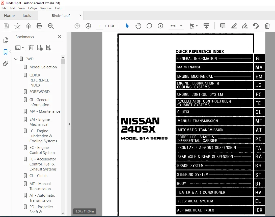
QUICK REFERENCE INDEX 1
FOREWORD 2
GI – General Information 0
MA – Maintenance 0
EM – Engine Mechanical 0
LC – Engine Lubrication & Cooling Systems 0
EC – Engine Control System 0
FE – Accelerator Control, Fuel & Exhaust Systems 0
CL – Clutch 0
MT – Manual Transmission 0
AT – Automatic Transmission 0
PD – Propeller Shaft & Differential Carrier 0
FA – Front Axle & Front Suspension 0
RA – Rear Axle & Rear Suspension 0
BR – Brake System 0
ST – Steering System 0
BF – Body 0
HA – Heater & Air Conditioner 0
EL – Electrical System 0
IDX – Alphabetical Index 1
Foldout 0
Quick Reference Chart 3
1995_240SX_Body_Repair_Manual 4
1995 Nissan 240SX Body Repair Manual 4
5S1495 4
Table of Contents 4
AT 36
QUICK REFERENCE INDEX 0
TABLE OF CONTENTS 36
PREPERATION AND PRECAUTIONS 37
Special Service Tools 37
Service Notice 38
Supplemental Restraint System “AIR BAG” 39
DESCRIPTION 40
Cross-sectional View 40
Hydraulic Control Circuit 41
Shift Mechanism 42
Control System 44
TROUBLE DIAGNOSES 46
Contents 46
A/T Electrical Parts Location 69
Wiring Diagram – AT – 71
Self Diagnosis 76
DTC P0720 VEHICLE SPEED SENSOR A/T (REVOLUTION SENSOR) CIRCUIT CHECK 81
VEHICLE SPEED SENSOR MTR CIRCUIT CHECK 83
DTC P1705 THROTTLE POSITION SENSOR CIRCUIT CHECK 85
DTC P0750 SHIFT SOLENOID VALVE A CIRCUIT CHECK 87
DTC P0755 SHIFT SOLENOID VALVE B CIRCUIT CHECK 89
DTC P1760 OVERRUN CLUTCH SOLENOID VALVE CIRCUIT CHECK 91
DTC P0740 TORQUE CONVERTER CLUTCH SOLENOID VALVE CIRCUIT CHECK 93
DTC P0710 FLUID TEMPERATURE SENSOR CIRCUIT AND A/T CONTROL UNIT POWER SOURCE CIRCUIT CHECKS 95
DTC P0725 ENGINE SPEED SIGNAL CIRCUIT CHECK 98
DTC P0745 LINE PRESSURE SOLENOID VALVE CIRCUIT CHECK 100
DTC P0705 INHIBITOR, OVERDRIVE AND THROTTLE POSITION SWITCH CIRCUIT CHECK 102
DTC P0731 IMPROPER SHIFTING TO 1ST GEAR POSITION 107
DTC P0732 IMPROPER SHIFTING TO 2ND GEAR POSITION 109
DTC P0733 IMPROPER SHIFTING TO 3RD GEAR POSITION 111
DTC P0734 IMPROPER SHIFTING TO 4TH GEAR POSITION 113
Diagnostic Procedures for Symptoms 115
TROUBLE DIAGNOSES – A/T Shift Lock System 145
Contents 145
Shift Lock System Electrical Parts Location 146
Wiring Diagram – SHIFT – 147
ON-VEHICLE SERVICE 156
Control Valve Assembly and Accumulators Inspection 156
Revolution Sensor Replacement 156
Rear Oil Seal Replacement 157
Parking Components Inspection 157
Inhibitor Switch Adjustment 158
Manual Control Linkage Adjustment 158
Kickdown Switch Adjustment 158
REMOVAL AND INSTALLATION 159
Removal 159
Installation 161
MAJOR OVERHAUL 163
Oil Channel 165
Location of Needle Bearings, Thrust Washers and Snap Rings 166
DISASSEMBLY 167
Disassembly 167
REPAIR FOR COMPONENT PARTS 178
Oil Pump 178
Control Valve Assembly 182
Control Valve Upper Body 188
Control Valve Lower Body 193
Reverse Clutch 195
High Clutch 199
Forward and Overrun Clutches 201
Low & Reverse Brake 205
Forward Clutch Drum Assembly 209
Rear Internal Gear and Forward Clutch Hub 211
Band Servo Piston Assembly 214
Parking Pawl Components 218
ASSEMBLY 220
Assembly (1) 220
Adjustment 224
Assembly (2) 228
SERVICE DATA AND SPECIFICATIONS (SDS) 238
General Specifications 238
Specifications and Adjustment 238
BF 242
QUICK REFERENCE INDEX 0
TABLE OF CONTENTS 242
GENERAL SERVICING 244
Precautions 244
Supplemental Restraint System “AIR BAG” 244
Circuit Breaker Inspection 244
Clip and Fastener 245
BODY END 248
Body Front End 248
Body Rear End and Opener 250
DOOR 252
Door Glass Fitting Adjustment 253
POWER WINDOW 256
System Description 256
Wiring Diagram – WINDOW – 258
Schematic 261
Trouble Diagnosis 262
POWER DOOR LOCK 268
System Description 268
Wiring Diagram – D/LOCK – 269
Trouble Diagnosis 271
MULTI-REMOTE CONTROL SYSTEM 274
System Description 274
Wiring Diagram – MULTI – 276
Schematic 279
Input/Output Operation Signal 280
Trouble Diagnoses 281
Replacing Remote Controller or Control Unit 287
INSTRUMENT PANEL 288
INTERIOR AND EXTERIOR 291
Interior 291
Exterior 296
SEAT 301
Front Seat 301
Rear Seat 303
SEAT BELTS 304
Front Seat Belt 304
Rear Seat Belt 305
SUN ROOF 306
Wiring Diagram – SROOF – 310
WINDSHIELD AND WINDOWS 311
Windshield and Rear Window 311
Side Window 312
DOOR MIRROR 313
Wiring Diagram – MIRROR – 314
REAR AIR SPOILER 316
Rear Air Spoiler 316
BODY ALIGNMENT 317
Engine Compartment 317
Underbody 319
SUPPLEMENTAL RESTRAINT SYSTEM (SRS) 321
Precautions for SRS “Air Bag” Service 321
Special Service Tools 321
Commercial Service Tool 321
Description 322
Caution Labels and SRS Component Parts Location 323
Maintenance Items 325
Removal and Installation – Diagnosis Sensor Unit 326
Removal – Air Bag Module and Spiral Cable 327
Removal – Front Passenger Air Bag Module 328
Installation – Air Bag Module and Spiral Cable 329
Installation – Front Passenger Air Bag Module 330
Disposal of Air Bag Module 330
TROUBLE DIAGNOSES – Supplemental Restraint System (SRS) 334
Wiring Diagram – SRS – 334
Schematic 336
Self-diagnosis 337
Diagnostic Procedure 1 342
Diagnostic Procedure 2 342
Diagnostic Procedure 3 343
Collision Diagnosis 344
BR 345
QUICK REFERENCE INDEX 0
TABLE OF CONTENTS 345
PRECAUTIONS AND PREPARATION 346
Precautions 346
Commercial Service Tools 346
BRAKE HYDRAULIC LINE/CONTROL VALVE 347
Brake Hydraulic Line 347
Dual Proportioning Valve 348
CHECK AND ADJUSTMENT 349
Checking Brake Fluid Level 349
Checking Brake Line 349
Changing Brake Fluid 349
Bleeding Brake System 349
BRAKE PEDAL AND BRACKET 350
Removal and Installation 350
Inspection 350
Adjustment 350
MASTER CYLINDER 351
Removal 351
Disassembly 351
Inspection 352
Assembly 352
Installatiion 352
BRAKE BOOSTER/VACUUM HOSE 353
Brake Booster 353
Vacuum Hose 354
FRONT DISC BRAKE 355
Pad Replacement 355
Removal 356
Disassembly 356
Inspection – Caliper 356
Inspection – Rotor 357
Assembly 357
Installation 357
REAR DISC BRAKE 358
Pad Replacement 358
Removal 360
Disassembly 360
Inspection – Caliper 361
Inspection – Rotor 362
Assembly 362
Installation 363
PARKING BRAKE CONTROL 364
Removal and Installation 364
Inspection 365
Adjustment 365
ANTI-LOCK BRAKE SYSTEM 366
Purpose 366
Operation 366
ABS Hydraulic Circuit 366
System Components 367
System Description 367
Removal and Installation 369
Wiring Diagram – ABS – 371
TROUBLE DIAGNOSES 376
Contents 376
How to Perform Trouble Diagnoses for Quick and Accurate Repair 376
SERVICE DATA AND SPECIFICATIONS (SDS) 409
General Specifications 409
Inspection and Adjustment 409
CL 410
QUICK REFERENCE INDEX 0
TABLE OF CONTENTS 410
PRECAUTIONS AND PREPARATION 411
Precautions 411
Special Service Tools 411
Commercial Service Tools 411
CLUTCH SYSTEM 412
INSPECTION AND ADJUSTMENT 413
Adjusting Clutch Pedal 413
Bleeding Procedure 414
HYDRAULIC CLUTCH CONTROL 415
Clutch Master Cylinder 415
Operating Cylinder 416
CLUTCH RELEASE MECHANISM 417
CLUTCH DISC AND CLUTCH COVER 419
Clutch Cover and Flywheel 419
Clutch Disc 420
SERVICE DATA AND SPECIFICATIONS (SDS) 421
General Specifications 421
Inspection and Adjustment 421
EC 422
QUICK REFERENCE INDEX 0
TABLE OF CONTENTS 422
PRECAUTIONS AND PREPARATION 424
Special Service Tool 424
Supplemental Restraint System “AIR BAG” 424
Precautions for On-Board Diagnostic (OBD) System of Engine and A/T 424
Engine Fuel & Emission Control System 425
Precautions 426
ENGINE AND EMISSION CONTROL OVERALL SYSTEM 428
Circuit Diagram 428
System Diagram 429
ECCS Component Parts Location 430
Vacuum Hose Drawing 432
System Chart 433
ENGINE AND EMISSION BASIC CONTROL SYSTEM DESCRIPTION 434
Multiport Fuel Injection (MFI) System 434
Distributor Ignition (DI) System 436
Air Conditioner Cut Control 437
Fuel Cut Control (at no load & high engine speed) 438
EVAPORATIVE EMISSION SYSTEM 439
Description 439
Inspection 439
POSITIVE CRANKCASE VENTILATION 441
Description 441
Inspection 441
BASIC SERVICE PROCEDURE 442
Fuel Pressure Release 442
Fuel Pressure Check 442
Injector Removal and Installation 443
Idle speed/Ignition Timing/Idle Mixture Ratio Adjustment 444
ON-BOARD DIAGNOSTIC SYSTEM DESCRIPTION 450
Introduction 450
Two Trip Detection Logic 450
Diagnostic Trouble Code (DTC) 450
Freeze Frame Data 451
Malfunction Indicator Lamp (MIL) 452
OBD System Operation Chart 455
Consult 460
Generic Scan Tool (GST) 472
TROUBLE DIAGNOSIS – General Description 474
Introduction 474
Work Flow 475
Description for Work Flow 476
Diagnostic Worksheet 477
Alphabetical & P No Index for DTC 478
Diagnostic Trouble Code (DTC) Chart 479
Fail-Safe Chart 488
Basic Inspection 489
Symptom Matrix Chart 492
Consult Reference Value in Data Monitor Mode 495
Major Sensor Reference Graph in Data Monitor Mode 498
ECM Terminals and Reference Value 500
TROUBLE DIAGNOSIS FOR POWER SUPPLY 506
Main Power Supply and Ground Circuit 506
DTC 11, Camshaft Position Sensor (CMPS) (DTC: P0340) 509
DTC 12, Mass Air Flow Sensor (MAFS) (DTC: P0100) 513
DTC 13, Engine Coolant Temperature Sensor (ECTS) (DTC: P0115) 518
DTC 14, Vehicle Speed Sensor (VSS) (DTC: P0500) 522
DTC 21, Ignition Signal (DTC: P1320) 526
DTC 25, Idle Air Control Valve (IACV) – Auxiliary Air Control (AAC) Valve (DTC: P0505) 531
DTC 31, Engine Control Module (ECM)-ECCS Control Module (DTC: P0605) 536
DTC 32, EGR Function (DTC:P0400) 538
DTC 33, Front Oxygen Sensor (Front O2S) (DTC: P0130) 546
DTC 34, Knock Sensor (KS) (DTC: P0325) 551
DTC 35, EGR Temperature Sensor (DTC: P1401) 554
DTC 36, EGRC-BPT Valve Function (DTC: P0402) 558
DTC 37, Closed Loop Control (DTC: P0130) 560
DTC 41, Intake Air Temperature Sensor (DTC: P0110) 561
DTC 43, Throttle Position Sensor (DTC: P0120) 566
DTC 65 – 71, No 4 – 1 Cylinder Misfire, Multiple Cylinder (DTC: P0304 – P0300) 571
DTC 72, Three Way Catalyst Function (DTC: P0420) 575
DTC 76, Fuel Injection System Function (DTC: P0170) 578
DTC 77, Rear Heated Oxygen Sensor (Rear HO2S) (DTC: P0136) 583
DTC 82, Crankshaft Position Sensor (CKPS) (OBD) (DTC: P0335) 588
DTC 84, A/T Diagnosis Communication Line (DTC: P1605) 592
DTC 95, Crankshaft Position Sensor (CKPS) (OBD) (DTC: P1336) 595
DTC 98, Engine Coolant Temperature (ECT) Sensor (DTC: P0125) 599
DTC 103, Park/Neutral Position Switch (DTC: P0705) 604
DTC 105, EGR and Canister Control Solenoid Valve (DTC: P1400) 609
DTC P0600, A/T Control (DTC: P0600) 613
TROUBLE DIAGNOSIS FOR NON-DETECTABLE ITEMS 616
Injector 616
Start Signal 619
Fuel Pump 621
Cooling Fan Control 626
Power Steering Oil Pressure Switch 634
IACV-Air Regulator 637
IACV-FICD Solenoid Valve 640
5th Position Switch 644
Rear Window Defogger Signal 646
MIL & Data Link Connectors 648
SERVICE DATA AND SPECIFICATIONS (SDS) 649
General Specifications 649
Inspection and Adjustment 649
EL 651
QUICK REFERENCE INDEX 0
TABLE OF CONTENTS 651
PRECAUTIONS 653
Supplemental Restraint System “AIR BAG” 653
HARNESS CONNECTOR 654
Description 654
STANDARDIZED RELAY 655
Description 655
POWER SUPPLY ROUTING 658
Schematic 658
Wiring Diagram – POWER – 660
Fuse 669
Fusible Link 669
BATTERY 670
How to Handle Battery 670
Service Data and Specifications (SDS) 673
STARTING SYSTEM 674
System Description 674
Wiring Diagram – START – 676
Construction 679
Removal and Installation 679
Pinion/Clutch Check 680
Service Data and Specifications (SDS) 680
CHARGING SYSTEM 681
System Description 681
Wiring Diagram – CHARGE – 682
Construction 683
Removal and Installation 684
Service Data and Specifications (SDS) 684
COMBINATION SWITCH 685
Combination Switch/Check 685
Replacement 686
Steering Switch/Check 687
HEADLAMP 688
System Description (For USA) 688
Schematic (For USA) 689
Wiring Diagram (For USA) – H/LAMP – 690
Trouble Diagnoses (For USA) 691
System Description (For Canada) 692
Operation (Daytime light system for Canada) 693
Schematic (For Canada) 694
Wiring Diagram (For Canada) – DTRL – 695
Trouble Diagnoses (For Canada) 698
Bulb Replacement 699
Aiming Adjustment 699
EXTERIOR LAMP 701
Clearance, License, Tail and Stop Lamps/Wiring Diagram – TAIL/L – 701
Back-up Lamp/Wiring Diagram – BACK/L – 703
Front Fog Lamp/System Description 705
Front Fog Lamp/Wiring Diagram – F/FOG – 706
Front Fog Lamp Aiming Adjustment 707
Turn Signal and Hazard Warning Lamps/System Description 708
Turn Signal and Hazard Warning Lamps/Schematic 710
Turn Signal and Hazard Warning Lamps/Wiring Diagram – TURN 711
Turn Signal and Hazard Warning Lamps/Trouble Diagnoses 714
Combination Flasher Unit Check 714
Bulb Specifications 715
INTERIOR LAMP 716
Illumination/System Description 716
Illumination/Schematic 717
Ilumination/Wiring Diagram – ILL – 718
Interior, Spot and Trunk Room Lamps/System Description 721
Bulb Specifications 721
Interior, Spot and Trunk Room Lamps/Wiring Diagram – INT – 722
METER AND GAUGES 724
System Description 724
Combination Meter 725
Speedometer, Tachometer, Temp and Fuel Gauges/Wiring Diagram – METER – 726
Inspection/Fuel Gauge and Water Temperature Gauge 727
Inspection/Tachometer 728
Inspection/Speedometer and Vehicle Speed Sensor 729
Fuel Tank Gauge Unit Check 731
Fuel Warning Lamp Sensor Check 731
Oil Pressure Switch Check 731
Vehicle Speed Sensor Signal Check 732
WARNING LAMPS AND BUZZER 733
Warning Lamps/Schematic 733
Warning Lamps/Wiring Diagram – WARN – 734
Warning Buzzer/System Description 736
Warning Buzzer/Wiring Diagram – CHIME – 738
Trouble Diagnoses – Warning Buzzer 740
Diode Check 749
Warning Buzzer Check 749
WIPER AND WASHER 750
System Description 750
Front Wiper and Washer/Wiring Diagram – WIPER – 752
Trouble Diagnoses 754
Wiper Amplifier Check 756
Wiper Installation and Adjustment 756
Washer Nozzle Adjustment 756
Washer Tube Layout 757
Wiper Linkage 758
HORN, CIGARETTE LIGHTER AND CLOCK 759
Wiring Diagram – HORN – 759
REAR WINDOW DEFIGGER 760
System Description 760
Wiring Diagram – DEF – 761
Trouble Diagnoses 763
Filament Check 765
Filament Repair 766
AUDIO AND POWER ANTENNA 768
Audio/System Description 768
Audio/Schematic 769
Audio/Wiring Diagram – AUDIO – 770
Power Antenna/System Description 774
Power Antenna/Wiring Diagram – P/ANT – 775
Trouble Diagnoses 776
Location of Antenna 777
Antenna Rod Replacement 778
Window Antenna Repair 778
AUTOMATIC SPEED CONTROL DEVICE (ASCD) 780
System Description 780
Fail-safe System 782
Component Parts and Harness Connector Location 783
Schematic 784
Wiring Diagram – ASCD – 785
Trouble Diagnoses 790
ASCD Wire Adjustment 808
THEFT WARNING SYSTEM 809
System Description 809
Component Parts and Harness Connector Location 812
Schematic 813
Wiring Diagram – THEFT – 814
Trouble Diagnoses 821
LOCATION OF ELECTRICAL UNITS 840
Engine Compartment 840
Passenger Compartment 841
HARNESS LAYOUT 843
Outline 843
Main Harness 844
Engine Room Harness 846
Engine Control Harness 849
Body Harness and Tail Harness 850
Engine Harness 852
Room Lamp 853
Air Bag Harness 854
Door Harness LH 855
Door Harness RH 855
SUPER MULTIPLE JUNCTION (SMJ) 0
Disconnecting and Connecting 0
Terminal Arrangement 1
EM 856
QUICK REFERENCE INDEX 0
TABLE OF CONTENTS 856
PRECAUTIONS 857
Parts Requiring Angular Tightening 857
Liquid Gasket Application Procedure 857
PREPARATION 858
Special Service Tools 858
Commercial Service Tools 861
OUTER COMPONENT PARTS 862
COMPRESSION PRESSURE 864
Measurement of Compression Pressure 864
OIL PAN 865
Removal 864
Installation 866
TIMING CHAIN 867
Removal 869
Inspection 871
Installation 871
OIL SEAL REPLACEMENT 876
CYLINDER HEAD 878
Removal and Installation 879
Disassemblly 879
Inspection 879
Assembly 884
Valve Clearance 885
ENGINE REMOVAL 887
Removal 888
CYLINDER BLOCK 889
Disassembly 890
Inspection 891
Assembly 897
SERVICE DATA AND SPECIFICATIONS 901
General Specifications 901
Inspection and Adjustment 901
FA 909
QUICK REFERENCE INDEX 0
TABLE OF CONTENTS 909
PRECAUTIONS AND PREPARATION 910
Precautions 910
Special Service Tools 910
Commercial Service Tools 911
FRONT SUSPENSION SYSTEM 912
ON-VEHICLE SERVICE 913
Front Axle and Front Suspension Parts 913
Front Wheel Bearing 914
Front Wheel Alignment 914
FRONT AXLE 916
Wheel Hub and Knuckle 916
ABS Sensor Rotor 918
Baffle Plate 918
FRONT SUSPENSION 919
Coil Spring and Strut Assembly 920
Tension Rod and Stabilizer Bar 921
Transverse Link and Lower Ball Joint 922
SERVICE DATA AND SPECIFICATIONS (SDS) 923
General Specifications 923
Inspection and Adjustment 923
FE 924
QUICK REFERENCE INDEX 0
TABLE OF CONTENTS 924
PREPARATION/ACCELERATOR CONTROL SYSTEM 925
Special Service Tool 925
Accelerator Control System 925
Adjusting Accelerator Wire 925
FUEL SYSTEM 926
Fuel Tank 926
Fuel Pump and Gauge 928
EXHAUST SYSTEM 930
Foldout 931
QUICK REFERENCE INDEX 0
ELECTRICAL SYSTEM 1
SUPER MULTIPLE JUNCTION (SMJ) 931
Disconnecting and Connecting 931
Terminal Arrangement 932
GI 934
QUICK REFERENCE INDEX 0
TABLE OF CONTENTS 934
PRECAUTIONS 935
Precautions for Supplemental Restraint System “AIR BAG” 935
General Precautions 935
Precautions for Multiport Fuel Injection System or ECCS Engine 937
Precautions for Three Way Catalyst 938
Precautions for Fuel 938
HOW TO USE THIS MANUAL 939
HOW TO READ WIRING DIAGRAMS 941
Sample/Wiring Diagram – EXAMPL – 941
Description 943
Wiring Diagram Codes (Cell Codes) 949
HOW TO PERFORM EFFICIENT DIANOSIS FOR AN ELECTRICAL INCIDENT 950
Work Flow 950
Incident Simulation Tests 951
Circuit Inspection 955
HOW TO FOLLOW FLOW CHART IN TROUBLE DIAGNOSES 961
CONSULT CHECKING SYSTEM 964
Function and System Application 964
Checking Equipment 964
IDENTIFICATION INFORMATION 965
Model Variation 965
Identification Number 966
Dimensions 968
Wheels and Tires 968
LIFTING POINTS AND TOW TRUCK TOWING 969
Garage Jack and Safety Stand 969
2-pole Lift 970
Preparation 970
Board-on Lift 970
Tow Truck Towing 971
TIGHTENING TORQUE OF STANDARD BOLTS 972
SAE J1930 TERMINOLOGY LIST 973
SAE J1930 Terminology List 973
HA 977
QUICK REFERENCE INDEX 0
TABLE OF CONTENTS 977
PRECAUTIONS AND PREPARATION 978
Supplemental Restraint System “AIR BAG” 978
Precautions for Working with HFC-134a (R-134a) 978
General Refrigerant Precautions 978
Precautions for Refrigerant Connection 979
Precautions for Servicing Compressor 980
Special Service Tools 980
HFC-134a (R-134a) Service Tools and Equipment 981
Precautions for Service Equipment 983
DESCRIPTION 985
Refrigeration Cycle 985
Component Layout 986
Discharge Air Flow 987
Control Operation 988
V-6 Variable Displacement Compressor 989
TROUBLE DIAGNOSES 994
Contents 994
Wiring Diagram – A/C – 1016
SERVICE PROCEDURES 1039
HFC-134a (R-134a) Service Procedure 1039
Maintenance of Oil Quantity in Compressor 1041
Refrigerant Lines 1043
Compressor Mounting 1044
Belt Tension 1044
Fast Idle Control Device (FICD) 1044
SERVICE PROCEDURES – Push Control 1045
Overhaul – Push Control Unit Assembly 1045
Disassembly 1045
COMPRESSOR – Model V-6 (CALSONIC make) 1046
Compressor Clutch 1046
SERVICE DATA AND SPECIFICATIONS 1049
General Specifications 1049
Inspection and Adjustment 1049
IDX 1050
QUICK REFERENCE INDEX 0
LC 1057
QUICK REFERENCE INDEX 0
TABLE OF CONTENTS 1057
PRECAUTION AND PREPARATION 1058
Precaution 1058
Special Service Tools 1058
ENGINE LUBRICATION SYSTEM 1059
Lubrication Circuit 1059
Oil Pressure Check 1059
Oil Pump 1060
ENGINE COOLING SYSTEM 1062
Cooling Circuit 1062
System Check 1062
Water Pump 1063
Thermostat 1064
Radiator 1065
Cooling Fan 1065
SERVICE DATA AND SPECIFICATIONS (SDS) 1066
Engine Lubrication System 1066
Engine Cooling System 1066
MA 1067
QUICK REFERENCE INDEX 0
TABLE OF CONTENTS 1067
PRECAUTIONS 1068
Supplemental Restraint System “AIR BAG” 1068
GENERAL MAINTENANCE 1069
PERIODIC MAINTENANCE 1071
Schedule 1 1072
Schedule 2 1073
RECOMMENDED FLUIDS AND LUBRICANTS 1074
Fluids and Lubricants 1074
SAE Viscosity Number 1074
ENGINE MAINTENANCE 1075
Checking Drive Belts 1075
Changing Engine Coolant 1076
Checking Fuel Lines 1077
Changing Fuel Filter 1077
Changing Air Cleaner Filter 1078
Changing Engine Oil 1078
Changing Oil Filter 1079
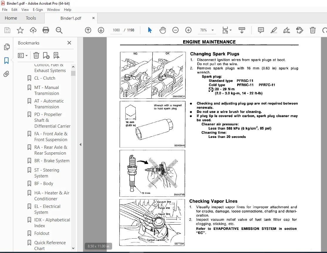
Changing Spark Plugs 1080
Checking Vapor Lines 1080
CHASSIS AND BODY MAINTENANCE 1081
Checking Exhaust System 1081
Checking Clutch Fluid Level and Leaks 1081
Checking M/T Oil 1081
Changing M/T Oil 1081
Checking A/T Fluid 1082
Changing A/T Fluid 1082
Checking Differential Gear Oil 1082
Changing Differential Gear Oil 1083
Balancing Wheels 1083
Tire Rotation 1083
Checking Brake Fluid Level and Leaks 1083
Checking Brake Lines and Cables 1083
Checking Disc Brake 1083
Checking Steering Gear and Linkage 1084
Checking Power Steering Fluid and Lines 1084
Lubricating Locks, Hinges and Hood Latches 1085
Checking Seat Belts, Buckles, Retractors, Anchors and Adjusters 1085
SERVICE DATA AND SPECIFICATIONS (SDS) 1086
Engine Maintenance 1086
Chassis and Body Maintenance 1086
MT 1087
QUICK REFERENCE INDEX 0
TABLE OF CONTENTS 1087
PREPARATION 1088
Special Service Tools 1088
Commercial Service Tool 1090
ON-VEHICLE SERVICE 1091
Replacing Rear Oil Seal 1091
Check of Position Switches 1091
REMOVAL AND INSTALLATION 1092
Removal 1092
Installation 1093
MAJOR OVERHAUL 1094
Case Components 1094
Gear Components 1095
Shift Control Components 1096
DISASSEMBLY 1097
Case Components 1097
Shift Control Components 1098
Gear Components 1098
INSPECTION 1101
Shift Control Components 1101
Gear Components 1101
ASSEMBLY 1103
Gear Components 1103
Shift Control Components 1109
Case Components 1110
SERVICE DATA AND SPECIFICATIONS 1113
General Specifications 1113
Inspection and Adjustment 1114
PD 1116
QUICK REFERENCE INDEX 0
TABLE OF CONTENTS 1116
PREPARATION 1117
Special Service Tools 1117
Commercial Service Tool 1119
PROPELLER SHAFT 1120
On-vehicle Service 1121
Removal 1121
Installation 1121
Inspection 1122
Disassembly 1123
Assembly 1123
FINAL DRIVE 1124
ON-VEHICLE SERVICE/REMOVAL AND INSTALLATION 1124
Front Oil Seal Replacement 1124
Side Oil Seal Replacement 1124
Removal 1125
Installation 1126
FINAL DRVIE 1127
DISASSEMBLY 1129
Pre-inspection 1129
Differential Carrier 1129
Differential Case 1131
INSPECTION 1133
Ring Gear and Drive Pinion 1133
Bearing 1133
Differential Case Assembly 1133
ADJUSTMENT 1134
Side Bearing Preload 1134
Pinion Gear Height and Pinion Bearing Preload 1135
Tooth Contact 1140
ASSEMBLY 1141
Differential Case 1141
Differential Carrier 1143
SERVICE DATA AND SPECIFICATIONS 1147
Propeller Shaft 1147
Final Drive 1147
RA 1149
QUICK REFERENCE INDEX 0
TABLE OF CONTENTS 1149
PRECAUTIONS AND PREPARATION 1150
Precautions 1150
Special Service Tools 1150
Commercial Service Tools 1151
REAR SUSPENSION SYSTEM 1152
ON-VEHICLE SERVICE 1153
Rear Axle and Rear Suspension Parts 1153
Rear Wheel Bearing 1153
Rear Wheel Alignment 1153
Drive Shaft 1154
REAR AXLE 1155
Wheel Hub and Axle Housing 1155
Drive Shaft 1159
REAR SUSPENSION 1165
Removal and Installation 1166
Coil Spring and Shock Absorber 1167
Multi-link and Lower Ball Joint 1168
Stabilizer Bar 1169
SERVICE DATA AND SPECIFICATIONS (SDS) 1170
General Specifications 1170
Inspection and Adjustment 1171
ST 1172
QUICK REFERENCE INDEX 0
TABLE OF CONTENTS 1172
PRECAUTIONS AND PREPARATION 1173
Precautions 1173
Special Service Tools 1173
Commercial Service Tools 1174
ON-VEHICLE SERVICE 1176
Checking Steering Wheel Play 1176
Checking Neutral Position on Steering Wheel 1176
Front Wheel Turning Angle 1176
Checking Gear Housing Movement 1177
Adjusting Rack Retainer 1177
Checking and Adjusting Drive Belts (For power steering) 1177
Checking Fluid Level 1177
Checking Fluid Leakage 1177
Bleeding Hydraulic System 1178
Checking Steering Wheel Turning Force (for power steering) 1178
Checking Hydraulic System 1179
STEERING WHEEL AND STEERING COLUMN 1180
Removal and Installation 1180
Disassembly and Assembly 1182
Inspection 1183
POWER STEERING GEAR AND LINKAGE (Model PR24AC) 1184
Removal and Installation 1184
Disassembly and Assembly 1186
Disassembly 1187
Inspection 1187
Assembly 1188
Adjustment 1192
POWER STEERING OIL PUMP 1194
Disassembly and Assembly 1194
Pre-disassembly Inspection 1194
Disassembly 1195
Inspection 1195
Assembly 1196
SERVICE DATA AND SPECIFICATIONS (SDS) 1197
General Specifications 1197
Inspection and Adjustment 1197
Contact us: [email protected]
https://vimeo.com/849397209?share=copy
DESCRIPTION:
1995 NISSAN 240SX S14 Series Service Manual PDF DOWNLOAD
FOREWORD:
- This manual contains maintenance .and repair procedures for the 1995 Nissan 240SX. In order to .assure your safety and the efficient functioning of the vehicle, this manual should be read thoroughly.
- It is especially important that the PRECAUTIONS in the GI section be completely understood before starting any repair task. All information In this manual Is based on the latest product information at the time of publication.
- The right is reserved to make changes in specifications and methods at any time without notice.
PLEASE NOTE:
- This is the same manual used by the dealers to diagnose and troubleshoot your vehicle
- You will be directed to the download page as soon as the purchase is completed. The whole payment and downloading process will take anywhere between 2-5 minutes
- Need any other service / repair / parts manual, please feel free to contact [email protected] . We still have 50,000 manuals unlisted
G.P