Trusted Business
Verified & Licensed
Virus Free Files
100% Safe Downloads
Secure Payment
SSL Protected
Instant Delivery
Available Immediately
1995 NISSAN 300ZX Z32 Series Service Manual PDF DOWNLOAD
$35.95
1995 NISSAN 300ZX Z32 Series Service Manual PDF DOWNLOAD
Instant PDF Download
Available immediately
Save to Your Device
Download & keep forever
Antivirus Scanned
100% virus-free
Trusted Worldwide
175,000+ customers
Description
1995 NISSAN 300ZX Z32 Series Service Manual PDF DOWNLOAD
FILE DETAILS:
1995 NISSAN 300ZX Z32 Series Service Manual PDF DOWNLOAD
Language : English
Pages : 1175
Downloadable :Yes
File Type : PDF
IMAGES PREVIEW OF THE MANUAL:
TABLE OF CONTENTS:
1995 NISSAN 300ZX Z32 Series Service Manual PDF DOWNLOAD
fwd 1
Model Selection 0
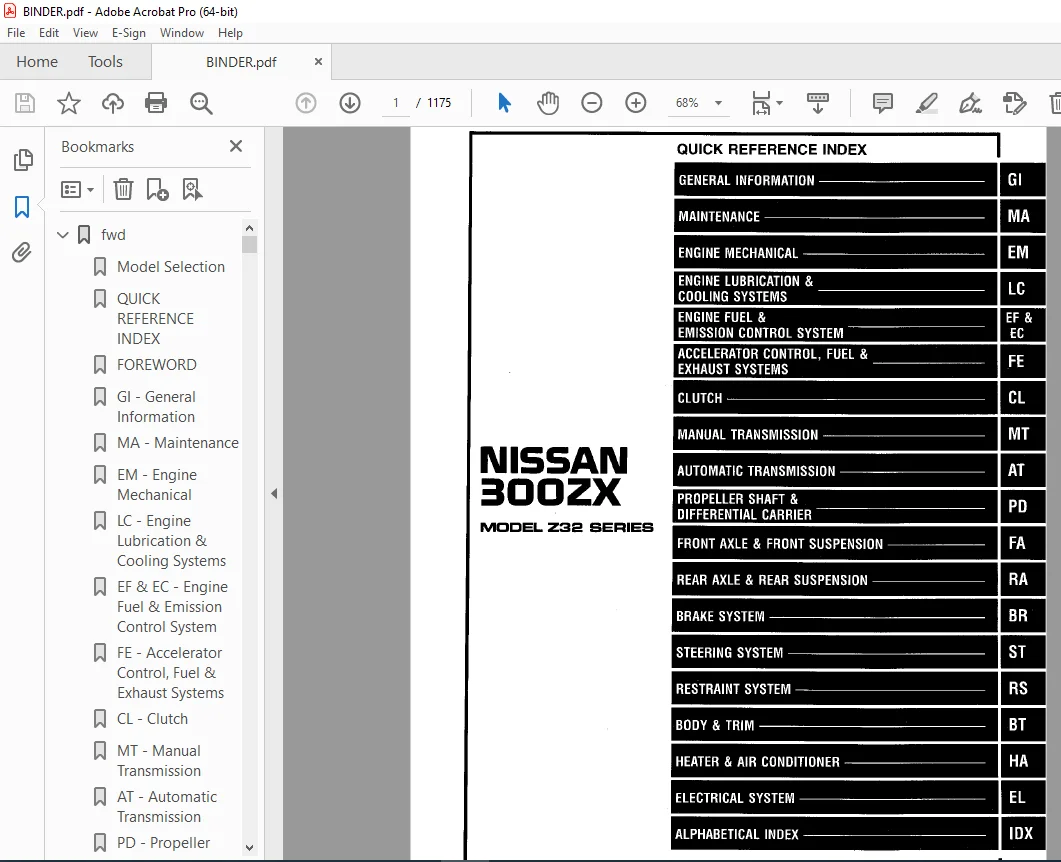
QUICK REFERENCE INDEX 1
FOREWORD 2
GI – General Information 0
MA – Maintenance 0
EM – Engine Mechanical 0
LC – Engine Lubrication & Cooling Systems 0
EF & EC – Engine Fuel & Emission Control System 0
FE – Accelerator Control, Fuel & Exhaust Systems 0
CL – Clutch 0
MT – Manual Transmission 0
AT – Automatic Transmission 0
PD – Propeller Shaft & Differential Carrier 0
FA – Front Axle & Front Suspension 0
RA – Rear Axle & Rear Suspension 0
BR – Brake System 0
ST – Steering System 0
RS – Restraint System 0
BT – Body & Trim 0
HA – Heater & Air Conditioner 0
EL – Electrical System 0
IDX – Alphabetical Index 1
Quick Reference Chart 3
at 4
QUICK REFERENCE INDEX 0
TABLE OF CONTENTS 4
PREPARATION AND PRECAUTIONS 5
Special Service Tools 5
Service Notice 6
Supplemental Restraint System (SRS) “AIR BAG” 7
DESCRIPTION 8
Cross-Sectional View 8
Hydraulic Control Circuits 9
Shift Mechanism 10
Control System 12
TROUBLE DIAGNOSES 14
Contents 14
A/T Electrical Parts Location 37
Wiring Diagram 39
TROUBLE DIAGNOSES – A/T Shift Lock System 91
Contents 91
Shift Lock Electrical Parts Location 91
Wiring Diagram 93
ON-VEHICLE SERVICE 100
Control Valve Assembly and Accumulators 100
Revolution Sensor Replacement 101
Rear Oil Seal Replacement 101
Parking Components Inspection 101
Manual Control Linkage Adjustment 102
Kickdown Switch Adjustment 102
REMOVAL AND INSTALLATION 103
Removal 103
Installation 103
MAJOR OVERHAUL 105
RE4R01A 105
RE4R03A 107
Oil Channel – RE4R01A 109
Oil Channel – RE4R03A 110
Locations of Needle Bearings, Thrust Washers and Snap Rings – RE4R01A 111
Locations of Needle Bearings, Thrust Washers and Snap Rings – RE4R03A 112
DISASSEMBLY 113
Disassembly 113
REPAIR FOR COMPONENT PARTS 124
Oil Pump 124
Control Valve Assembly 128
Control Valve Upper Body 134
Control Valve Lower Body 139
Reverse Clutch 141
High Clutch 145
Forward and Overrun Clutches 147
Low & Reverse Brake 151
Forward Clutch Drum Assembly – RE4R01A 155
Forward Clutch Drum Assembly – RE4R03A 158
Rear Internal Gear and Forward Clutch Hub 161
Band Servo Piston Assembly 164
Parking Pawl Components 168
ASSEMBLY 170
Assembly (1) 170
Adjustment 175
Assembly (2) 179
SERVICE DATA AND SPECIFICATIONS (SDS) 189
General Specifications 189
Specifications and Adjustment – RE4R01A 189
Specifications and Adjustment – RE4R03A 193
br 197
QUICK REFERENCE INDEX 0
TABLE OF CONTENTS 197
PRECAUTIONS AND PREPARATION 199
Precautions 199
Commercial Service Tools 199
CHECK AND ADJUSTMENT 200
Checking Brake Fluid Level 200
Changing Brake System 200
Changing Brake Fluid 200
Bleeding Brake System 200
BRAKE HYDRAULIC LINE 201
Removal and Installation 201
Inspection 201
BRAKE PEDAL AND BRACKET 202
Removal and Installation 202
Inspection 202
Adjustment 202
MASTER CYLINDER 204
Removal 204
Disassembly 204
Inspection 205
Assembly 205
Installation 205
BRAKE BOOSTER 206
Removal and Installation 206
Inspection 206
VACUUM PIPING 207
Removal and Installation 207
Inspection 207
FRONT DISC BRAKE (OPF25FA) 208
Pad Replacement 208
Removal and Installation 208
Disassembly 209
Inspection 209
Assembly 210
Inspection (On-vehicle) 210
REAR DISC BRAKE (OPZ11V) 211
Pad Replacement 211
Removal and Installation 212
Disassembly 212
Inspection 212
Assembly 213
Inspection (On-vehicle) 213
PARKING BRAKE CONTROL 214
Removal and Installation 214
Inspection 214
Adjustment 214
PARKING DRUM BRAKE (DS17HD) 215
Shoe Replacement 215
Shoe Clearance Adjustment 216
Breaking in Parking Brake Shoes 216
Drum Inspection 216
ANTI-LOCK BRAKE SYSTEM 217
System Components 217
Hydraulic Circuit 217
Wiring Diagram 218
Removal and Installation 219
TROUBLE DIAGNOSES 220
Contents 220
Component Parts and Harness Connector Location 224
SERVICE DATA AND SPECIFICATIONS (SDS) 242
General Specifications 242
Inspection and Adjustment 242
bt 243
QUICK REFERENCE INDEX 0
TABLE OF CONTENTS 243
GENERAL SERVICING 244
Precautions 244
Supplemental Restraint System (SRs) “AIR BAG” 244
Clip and Fastener 245
BODY END 247
Body Front End 247
Body Rear End and Opener 249
DOOR 252
INSTRUMENT PANEL 253
INTERIOR TRIM 255
Side, Luggage and Floor Trim 255
Trunk Room Trim – Convertible model 258
Door Trim 259
Back Door Trim – Standard model 260
Roof Trim – T-bar roof model 261
EXTERIOR TRIM 262
T-BAR ROOF 271
CONVERTIBLE ROOF 273
Storage Lid 273
Top Cover and Headliner 274
Linkage 275
Adjustment 277
SEAT 278
WINDSHIELD AND WINDOWS 280
Windshield 280
Side Window 281
Back Door Window 282
REAR AIR SPOILER AND MIRROR 283
Rear Air Spoiler 283
Door Mirror 283
BODY ALIGNMENT 284
Engine Compartment 284
Underbody 286
cl 290
QUICK REFERENCE INDEX 0
TABLE OF CONTENTS 290
PRECAUTIONS AND PREPARATION 291
Precautions 291
Special Service Tools 291
Commercial Service Tools 292
CLUTCH SYSTEM 293
INSPECTION AND ADJUSTMENT 295
Adjusting Clutch Pedal 295
Bleeding Procedure 296
HYDRAULIC CLUTCH CONTROL 297
Clutch Master Cylinder 297
Operating Cylinder 298
Clutch Booster 299
CLUTCH RELEASE MECHANISM 301
CLUTCH DISC AND CLUTCH COVER 303
Clutch Disc 303
Clutch Cover and Flywheel 304
SERVICE DATA AND SPECIFICATIONS (SDS) 305
General Specifications 305
Inspection and Adjustment 305
ec 306
QUICK REFERENCE INDEX 0
TABLE OF CONTENTS 306
PREPARATION 308
Special Service Tools 308
PRECAUTIONS 309
ENGINE AND EMISSION CONTROL OVERALL SYSTEM 310
ECCS Component Parts Location 310
System Diagram 312
System Chart 314
Vacuum Hose Drawing 315
Circuit Diagram 317
ENGINE AND EMISSION CONTROL PARTS DESCRIPTION 318
Engine Control Module (ECM)-ECCS Control Module 318
Camshaft Position Sensor (CMPS) 318
Mass Air Flow Sensor (MAFS) 318
Engine Coolant Temperature Sensor (ECTS) 318
Throttle Position Sensor (TPS) & Soft/Hard Closed Throttle Position (CTP) Switch 319
Fuel Injector 319
Pressure Regulator 320
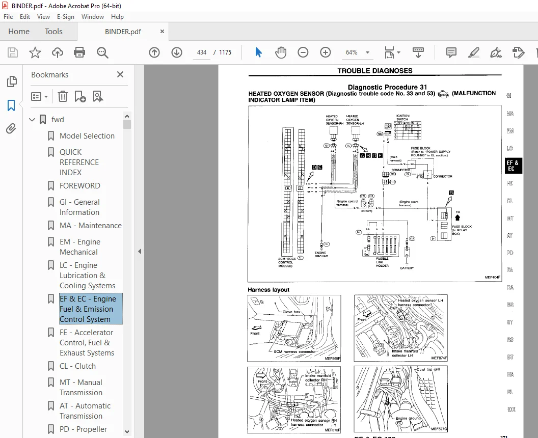
Heated Oxygen Sensor (HO2S) 320
Fuel Pump 320
Fuel Damper 320
Power Transistor Unit & Ignition Coil 321
Idle Air Control Valve (IACV)-Air Regulator 321
Idle Air Adjusting (IAA) Unit 321
Idle Air Control Valve (IACV)-Auxiliary Air Control (AAC) Valve 321
Power Steering Oil Pressure Switch 322
Vehicle Speed Sensor (VSS) 322
Knock Sensor (KS) 322
Exhaust Gas Recirculation (EGR) Valve 322
EGR Control (EGRC)-Solenoid Valve 323
Pressure Regulator Vacuum Relief (PRVR) Control Solenoid Valve 323
Wastegate Valve Control Solenoid Valve 323
Fuel Filter 323
Data Link Connector for CONSULT 323
EGR Temperature Sensor 324
Valve Timing Control Solenoid Valve 324
Carbon Canister 324
Fuel Temperature Sensor 324
Boost Pressure Sensor 324
ENGINE AND EMISSION CONTROL SYSTEM DESCRIPTION 325
Multiport Fuel Injection (MFI) System 325
Electronic Ignition (EI) System 327
Idle Air Control (IAC) System 328
Fuel Pump Control 329
Exhaust Gas Recirculation (EGR) System 330
Fuel Pressure Regulator Control 331
Air Conditioning Cut Control 331
Valve Timing Control 332
Cooling Fan Control 334
Wastegate Valve Control 335
Fail-safe System 336
Direct Ignition System 338
IDLE SPEED/IGNITION TIMING/IDLE MIXTURE RATIO INSPECTION 340
TROUBLE DIAGNOSES 346
Contents 346
MULTIPORT FUEL INJECTION SYSTEM INSPECTION 494
Releasing Fuel Pressure 494
Fuel Pressure Check 494
Injector Removal and Installation 495
EVAPORATIVE EMISSION SYSTEM 496
Description 496
Inspection 496
CRANKCASE EMISSION CONTROL SYSTEM 498
Description 498
Inspection 498
SERVICE DATA AND SPECIFICATIONS (SDS) 499
General Specifications 499
Inspection and Adjustment 499
el 500
QUICK REFERENCE INDEX 0
TABLE OF CONTENTS 500
PRECAUTIONS 502
Supplemental Restraint System (SRS) “AIR BAG” 502
Special Service Tools 502
HARNESS CONNECTOR 503
Description 503
STANDARDIZED RELAY 504
Description 504
POWER SUPPLY ROUTING 507
Wiring Diagram 507
Fuse Block Internal Circuit 509
Fuse 510
Fusible Link 510
Circuit Breaker Inspection 510
BATTERY 511
How to Handle Battery 511
Service Data and Specifications (SDS) 513
STARTING SYSTEM 514
Wiring Diagram 514
Construction 515
Removal and Installation 515
Service Data and Specifications (SDS) 516
CHARGING SYSTEM 517
Wiring Diagram 517
Construction 518
Removal and Installation 519
Service Data and Specifications (SDS) 520
COMBINATION SWITCH 521
Combination Switch/Check 521
Combination Switch/ Replacement 522
INSTRUMENT SWITCH 523
Check 523
HEADLAMP 525
Operation (Daytime light system equipped mode) 525
Schematic 525
Wiring Diagram 527
Aiming Adjustment 529
Bulb Replacement 530
EXTERIOR LAMP 531
Clearance, License, Tail and Stop Lamps/Wiring Diagram 531
Back-up Lamp/Wiring Diagram 532
Front Fog Lamp/Wiring Diagram 533
Turn Signal and Hazard Warning Lamps/Wiring Diagram 534
Stop and Tail Lamp Sensor Check 535
Combination Flasher Unit Check 535
Bulb Specifications 535
INTERIOR LAMP 536
Illumination/Wiring Diagram 536
Interior, Spot, Foot and Luggage Room Lamps/Wiring Diagram 537
METER AND GAUGES 539
Combination Meter 539
Speedometer, Tachometer, Temp , Oil, Fuel and Boost Gauges/Wiring Diagram 540
Inspection/Fuel Gauge and Water Temperature Gauge 541
Fuel Tank Gauge Unit Check 542
Fuel Warning Lamp Sensor Check 542
Thermal Transmitter Check 543
Oil Pressure Sending Unit Check 543
Boost Sensor Check 543
Vehicle Speed Sensor Signal Check 543
WARNING LAMPS AND CHIME 544
Warning Lamps/Schematic 544
Warning Lamps/Wiring Diagram 545
Warning Chime/Wiring Diagram 546
Diode Check 547
Warning Chime Check 547
TIME CONTROL SYSTEM 548
Description 548
Wiring Diagram 549
Trouble Diagnoses 550
WIPER AND WASHER 562
Front Wiper and Washer/Wiring Diagram 562
Rear Wiper and Washer/Wiring Diagram 563
Headlamp Washer/Wiring Diagram 564
Installation 565
Washer Nozzle Adjustment 566
Check Valve 566
Wiper Amplifier Check 566
POWER WINDOW 567
Wiring Diagram 567
Power Window Amp Inspection 568
POWER DOOR LOCK 569
Wiring Diagram 569
Door Lock Timer Inspection 570
Electrical Components Inspection 571
POWER DOOR MIRROR 572
Wiring Diagram 572
TRUNK LID AND FUEL FILLER LID OPENER 573
Wiring Diagram 573
CONVERTIBLE ROOF 574
Wiring Diagram 574
HORN, CIGARETTE LIGHTER, CLOCK 576
Wiring Diagram 576
REAR WINDOW DEFOGGER & HEATER MIRROR 577
Wiring Diagram 577
Filament Check 578
Filament Repair 579
AUDIO AND POWER ANTENNA 580
Audio/Wiring Diagram 580
Power Antenna/Wiring Diagram 582
Location of Antenna 583
Antenna Rod Replacement 583
Radio Fuse Check 584
Window Antenna Repair 585
POWER SEAT 586
Wiring Diagram – SEAT – 586
MULTI-REMOTE CONTROL SYSTEM 587
Wiring Diagram – MULTI – 587
Circuit Diagram for Quick Pinpoint Check 589
Trouble Diagnoses Preliminary Inspection 590
Trouble Diagnoses 591
Replacing Remote Controller or Control Unit 597
AUTOMATIC SPEED CONTROL DEVICE (ASCD) 598
Component Parts and Harness Connector Location 598
Wiring Diagram 599
Trouble Diagnoses 600
THEFT WARNING SYSTEM 618
Component Parts and Harness Connector Location 618
Wiring Diagram 619
Trouble Diagnoses 624
LOCATION OF ELECTRICAL UNITS 643
Engine Compartment 643
Passenger Compartment 644
Luggage Compartment 645
HARNESS LAYOUT 647
Outline 647
Engine Room Harness 648
Engine Control Harness 651
Main Harness 653
Air Bag Harness 656
Body Harness 657
Door Harness LH 663
Door Harness RH 663
Back Door Harness 664
Alternator Harness 664
em 665
QUICK REFERENCE INDEX 0
TABLE OF CONTENTS 665
PRECAUTIONS 666
Supplemental Restraint System “AIR BAG” 666
Parts Requiring Angular Tightening 666
Liquid Gasket Application Procedure 666
PREPARATION 667
Special Service Tools 667
Commercial Service Tools 669
OUTER COMPONENT PARTS 670
COMPRESSION PRESSURE 673
Measurement of Compression Pressure 673
OIL PAN 674
Removal 674
Installation 675
TIMING BELT 676
Removal 676
Inspection 678
Installation 679
OIL SEAL REPLACEMENT 683
THROTTLE BODIES 685
Precaution 685
Installation 685
CYLINDER HEAD 687
Removal 688
Disassembly 689
Inspection 690
Assembly 695
Installation 696
TURBOCHARGERS 698
Removal 698
Inspection 700
CHARGE AIR COOLERS 703
Removal 703
ENGINE REMOVAL 704
M/T Model 705
A/T Model 706
CYLINDER BLOCK 707
Disassembly 708
Inspection 708
Assembly 715
SERVICE DATA AND SPECIFICATIONS (SDS) 718
General Specifications 718
Inspection and Adjustment 719
fa 726
QUICK REFERENCE INDEX 0
TABLE OF CONTENTS 726
PRECAUTIONS AND PREPARATION 727
Precautions 727
Special Service Tools 727
Commercial Service Tools 727
FRONT AXLE AND FRONT SUSPENSION 729
ON-VEHICLE SERVICE 730
Front Axle and Front Suspension Parts 730
Front Wheel Bearing 732
Front Wheel Alignment 732
FRONT AXLE 734
Wheel Hub and Steering Knuckle 734
FRONT SUSPENSION 738
Coil Spring and Shock Absorber 739
Third Link and Upper Link 740
Tranverse Link and Lower Ball Joint 742
Tension Rod and Stabilizer Bar 743
ADJUSTABLE SHOCK ABSORBER 744
Trouble Diagnoses 745
SERVICE DATA AND SPECIFICATIONS (SDS) 751
General Specifications 751
Inspection and Adjustment 751
fe 753
QUICK REFERENCE INDEX 0
TABLE OF CONTENTS 753
ACCELERATOR CONTROL SYSTEM 754
Adjusting Accelerator Wire 754
FUEL SYSTEM 755
EXHAUST SYSTEM 757
gi 759
QUICK REFERENCE INDEX 0
TABLE OF CONTENTS 759
PRECAUTIONS 760
Precautions for Supplemental Restraint System “AIR BAG” 760
General Precautions 760
Precautions for Multiport Fuel Injection System or ECCS Engine 762
Precautions for Three Way Catalyst 762
Precautions for Turbocharger 762
Engine Oils 763
Precautions for Fuel 764
HOW TO USE THIS MANUAL 765
HOW TO READ WIRING DIAGRAMS 767
HOW TO PERFORM EFFICIENT DIAGNOSIS FOR AN ELECTRICAL INCIDENT 770
Work Flow 770
Incident Simulation Tests 771
Circuit Inspection 775
HOW TO FOLLOW FLOW CHART IN TROUBLE DIAGNOSES 781
CONSULT CHECKING SYSTEM 784
Function and System Application 784
Checking Equipment 784
IDENTIFICATION INFORMATION 785
Model Variation 785
Identification Number 787
Dimensions 789
Wheels and Tires 789
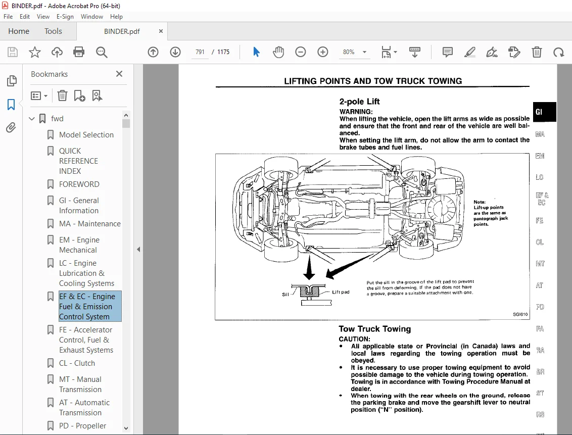
LIFTING POINTS AND TOW TRUCK TOWING 790
Garage Jack and Safety Stand 790
2-pole Lift 791
Tow Truck Towing 791
TIGHTENING TORQUE OF STANDARD BOLTS 793
SAE J1930 TERMINOLOGY LIST 794
ha 798
QUICK REFERENCE INDEX 0
TABLE OF CONTENTS 798
MANUAL AND AUTO 799
PRECAUTIONS AND PREPARATION 799
Supplemental Restraint System (SRS) “AIR BAG” 799
Introduction 799
Identification 799
Precautions for Working with HFC-134a (R-134a) 801
General Refrigerant Precautions 801
Precautions for Servicing Compressor 802
Special Service Tools 802
HFC-134a (R-134a) Service Tools and Equipment 804
Precautions for Service Equipment 806
DESCRIPTION 808
Refrigeration Cycle 808
Component Layout 809
Discharge Air Flow 810
Acceleration Cut System 811
Water Cock Control System 811
MANUAL 812
DESCRIPTION 812
Control Operation 812
TROUBLE DIAGNOSES 813
Contents 813
SYSTEM DESCRIPTION 855
Control Switches 855
Specifications 855
AUTO 857
DESCRIPTION 857
Features 857
Control Operation 858
TROUBLE DIAGNOSES 859
Contents 859
SYSTEM DESCRIPTION 913
Specifications 913
System Operation 916
MANUAL AND AUTO 920
SERVICE PROCEDURES 920
HFC-134a (R-134a) Service Procedure 920
Maintenance of Oil Quantity in Compressor 922
Refrigerant Lines 924
Compressor Mounting 926
Belt Tension 926
Fast idle Control Device (FICD) 926
Removal and Installation – Compressor 927
Compressor – Model DKS-16H (ZEXEL make) 928
SERVICE DATA AND SPECIFICATIONS (SDS) 930
General Specifications 930
Inspection and Adjustment 930
idx 931
QUICK REFERENCE INDEX 0
lc 939
QUICK REFERENCE INDEX 0
TABLE OF CONTENTS 939
PRECAUTIONS/PREPARATION 940
Supplemental Restraint System “AIR BAG” 940
Liquid Gasket Application Procedure 940
Special Service Tools 941
ENGINE LUBRICATION SYSTEM 942
Lubrication Circuit 942
Oil Pressure Check 943
Oil Filter Bracket (Turbocharger model) 943
Oil Pump 943
Oil Cooler (Turbocharger model) 945
ENGINE COOLING SYSTEM 946
Cooling Circuit 946
System Check 946
Water Pump 947
Thermostat 948
Cooling Fan (Crankshaft driven) 949
Radiator 950
Cooling Fan (Motor driven) 950
SERVICE DATA AND SPECIFICATIONS (SDS) 951
Engine Lubrication System 951
Engine Cooling System 951
ma 952
QUICK REFERENCE INDEX 0
TABLE OF CONTENTS 952
PRECAUTIONS 953
Supplemental Restraint System (SRS) “AIR BAG” 953
GENERAL MAINTENANCE 954
PERIODIC MAINTENANCE 956
Schedule 1 957
Schedule 2 958
RECOMMENDED FLUIDS AND LUBRICANTS 959
Fluids and Lubricants 959
SAE Viscosity Number 959
Anti-freeze Coolant Mixture Ratio 960
ENGINE MAINTENANCE 961
Checking Drive Belts 961
Changing Engine Coolant 962
Checking Fuel Lines 963
Changing Fuel Filter 964
Changing Air Cleaner Filter 964
Changing Engine Oil 964
Changing Oil Filter 965
Changing Spark Plugs 965
Checking Vapor Lines 966
CHASSIS AND BODY MAINTENANCE 966
Checking Exhaust System 966
Checking Clutch Fluid Level and Leaks 966
Checking M/T Oil 966
Changing M/T Oil 966
Checking A/T Fluid 966
Changing A/T Fluid 967
Checking Differential Gear Oil 968
Changing Differential Gear Oil 968
Balancing Wheels 969
Tire Rotation (Non-Turbocharger mode only) 969
Checking Brake Fluid Level and Leaks 969
Checking Brake Lines and Cables 969
Checking Disc Brake 969
Checking Steering Gear and Linkage 970
Checking Power Steering Fluid and Lines 970
Checking SUPER HICAS Linkage (With SUPER HICAS system) 971
Lubricating Locks, Hinges and Hood Latches 972
Checking Seat Belts, Buckles, Retractors, Anchors and Adjusters 972
SERVICE DATA AND SPECIFICATIONS (SDS) 973
Engine Maintenance 973
Chassis and Body Maintenance 973
mt 974
QUICK REFERENCE INDEX 0
TABLE OF CONTENTS 974
PREPARATION 975
Special Service Tools 975
Commercial Service Tool 977
ON-VEHICLE SERVICE 978
Replacing Rear Oil Seal 978
Position Switch Check 978
REMOVAL AND INSTALLATION 979
Removal 979
Installation 979
MAJOR OVERHAUL 980
Case Components 980
Gear Components 981
Shift Control Components 983
DISASSEMBLY 985
Case Components 985
Shift Control Components 986
Gear Components 987
INSPECTION 991
Shift Control Components 991
Gear Components 991
ASSEMBLY 993
Gear Components 993
Shift Control Components 1001
Case Components 1001
SERVICE DATA AND SPECIFICATIONS 1004
General Specifications 1004
Inspection and Adjustment 1004
pd 1006
QUICK REFERENCE INDEX 0
TABLE OF CONTENTS 1006
PREPARATION 1007
Special Service Tools 1007
Commercial Service Tools 1010
PROPELLER SHAFT 1011
On-vehicle Service 1012
Removal 1012
Installation 1013
Inspection 1013
Disassembly 1014
Assembly 1014
Final drive 1015
ON-VEHICLE SERVICE/REMOVAL AND INSTALLATION 1015
Front Oil Seal Replacement (R200V) 1015
Side Oil Seal Replacement 1015
Removal 1016
Installation 1016
FINAL DRIVE 1017
Model R200V 1017
Model R230V 1018
DISASSEMBLY 1019
Pre-inspection 1019
Differential Carrier 1019
Differential Case 1021
INSPECTION 1022
Ring Gear and Drive Pinion 1022
Bearing 1022
Differential Case Assembly 1022
ADJUSTMENT (R200V) 1023
Side Bearing Preload 1023
Pinion Gear Height and Pinion Bearing Preload 1024
ADJUSTMENT (R230V) 1029
Side Bearing Preload 1029
Pinion Gear Height 1030
ADJUSTMENT 1033
Tooth Contact 1033
ASSEMBLY 1034
Differential Case 1034
Differential Carrier 1035
SERVICE DATA AND SPECIFICATIONS (SDS) 1040
Propeller Shaft 1040
Final Drive 1040
ra 1043
QUICK REFERENCE INDEX 0
TABLE OF CONTENTS 1043
PRECAUTIONS AND PREPARATION 1044
Precautions 1044
Special Service Tools 1044
Commercial Service Tools 1045
REAR AXLE AND REAR SUSPENSION 1046
ON-VEHICLE SERVICE 1047
Rear Axle and Rear Suspension Parts 1047
Rear Wheel Bearing 1047
Rear Wheel Alignment 1047
Drive Shaft 1049
REAR AXLE AND REAR SUSPENSION ASSEMBLY 1050
Removal and Installation 1050
REAR AXLE 1051
Wheel Hub and Axle Housing 1051
Drive Shaft 1054
REAR SUSPENSION 1058
Coil Spring and Shock Absorber 1059
Multi-link and Lower Ball Joint 1060
Stabilizer Bar 1060
ADJUSTABLE SHOCK ABSORBER 1062
Removal and Installation 1062
Inspection 1062
Trouble Diagnoses 1062
SUPER HICAS 1063
Rear Wheel Alignment 1063
Rear Axle Housing Ball Joint 1064
SERVICE DATA AND SPECIFICATIONS (SDS) 1065
General Specifications 1065
Inspection and Adjustment 1066
rs 1067
QUICK REFERENCE INDEX 0
TABLE OF CONTENTS 1067
PRECAUTION 1068
Supplemental Restraint System (SRS) “AIR BAG” 1068
SEAT BELTS 1069
Front Seat Belt 1069
Rear Seat Belt (2 + 2 model) 1070
SUPPLEMENTAL RESTRAINT SYSTEM (SRS) 1071
Precautions for SRS “Air Bag” Service 1071
Special Service Tools 1071
Description 1072
SRS Component Parts Location 1073
Maintenance Items 1074
Removal and Installation – Diagnosis Unit and Sensor 1075
Removal – Air Bag Module and Spiral Cable 1076
Removal – Front Passenger Air Bag Module 1077
Installation – Air Bag Module and Sprial Cable 1078
Installation – Front Passenger Air Bag Module 1079
Disposal of Air Bag Module 1080
TROUBLE DIAGNOSES – Supplemental Restraint System (SRS) 1084
Schematic 1084
Wiring Diagram 1085
Self-diagnosis 1086
Diagnostic Procedure 1 1092
Diagnostic Procedure 2 1092
Diagnostic Procedure 3 1093
Collision Diagnosis 1094
st 1095
QUICK REFERENCE INDEX 0
TABLE OF CONTENTS 1095
PRECAUTIONS AND PREPARATION 1096
Supplemental Restraint System (SRS)”AIR BAG” 1096
Steering System 1096
Special Service Tools 1096
Commercial Service Tools 1098
CONSULT Program Card 1098
ON-VEHICLE SERVICE 1099
Checking Steering Wheel Play 1099
Checking Neutral Position on Steering Wheel 1099
Front Wheel Turning Angle 1099
Checking Gear Housing Movement 1100
Adjusting Rack Retainer 1100
Checking and Adjusting Drive Belts (For power steering) 1100
Checking Fluid Level 1100
Checking Fluid Leakage 1101
Bleeding Hydraulic System 1101
Checking Steering Wheel Turning Force (For power steering) 1101
Checking Hydraulic System 1102
STEERING WHEEL AND STEERING COLUMN 1103
Removal 1103
Installation 1103
Disassembly and Assembly 1103
Inspection 1104
POWER STEERING GEAR AND LINKAGE (Model PR26AE) 1106
Removal and Installation 1106
Disassembly 1109
Inspection 1109
Assembly 1110
Adjustment 1115
POWER STEERING OI PUMP 1117
Pre-disassembly Inspection 1117
Disassembly 1117
Inspection 1118
Assembly 1118
TWIN ORIFICE POWER STEERING SYSTEM 1120
Hydraulic Circuit 1120
Schematic 1120
Wiring Diagram 1121
Trouble Diagnoses 1122
SUPER HICAS SYSTEM 1131
HICAS Component Parts Location 1131
System Diagram 1131
On-vehicle Service 1132
Repair of Component Parts 1134
Trouble Diagnoses 1139
SERVICE DATA AND SPECIFICATIONS (SDS) 1174
General Specifications 1174
Inspection and Adjustment 1174
Contact us: [email protected]
https://vimeo.com/849851919?share=copy
DESCRIPTION:
1995 NISSAN 300ZX Z32 Series Service Manual PDF DOWNLOAD
FOREWORD
- This manual contains maintenance and repair procedures for the 1995 Nissan 300ZX. In order to assure your safety and the efficient functioning of the vehicle, this manual should be read thoroughly.
- It is especially important that the PRECAUTIONS in the GI section be completely understood before starting any repair task.
- All information in this manual is based on the latest product information at the time of publication. The right is reserved to make changes in specifications and methods at any time without notice.
IMPORTANT SAFETY NOTICE
- The proper performance of service is essential for both the safety of the technician and the efficient functioning of the vehicle.
- The service methods in this Service Manual are described in such a manner that the service may be performed safely and accurately.
- Service varies with the procedures used, the skills of the technician and the tools and parts available.
- Accordingly, anyone using service procedures, tools or parts which are not specifically recommended by NISSAN must first completely satisfy himself that neither his safety nor the vehicle’s safety will be jeopardized by the service method selected.
PLEASE NOTE:
- This is the same manual used by the dealers to diagnose and troubleshoot your vehicle
- You will be directed to the download page as soon as the purchase is completed. The whole payment and downloading process will take anywhere between 2-5 minutes
- Need any other service / repair / parts manual, please feel free to contact [email protected] . We still have 50,000 manuals unlisted
G.P