Trusted Business
Verified & Licensed
Virus Free Files
100% Safe Downloads
Secure Payment
SSL Protected
Instant Delivery
Available Immediately
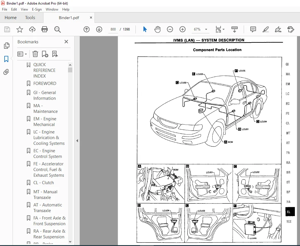
1995 NISSAN MAXIMA A32 Series Service Manual PDF DOWNLOAD
$24.95
1995 NISSAN MAXIMA A32 Series Service Manual PDF DOWNLOAD
Instant PDF Download
Available immediately
Save to Your Device
Download & keep forever
Antivirus Scanned
100% virus-free
Trusted Worldwide
175,000+ customers
Description
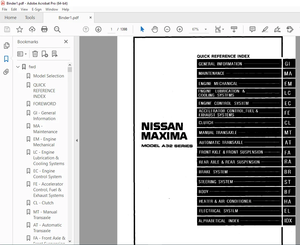
1995 NISSAN MAXIMA A32 Series Service Manual PDF DOWNLOAD
FILE DETAILS:
1995 NISSAN MAXIMA A32 Series Service Manual PDF DOWNLOAD
Language : English
Pages : 1398
Downloadable :Yes
File Type : PDF
Contact us: [email protected]
https://vimeo.com/852066285?share=copy
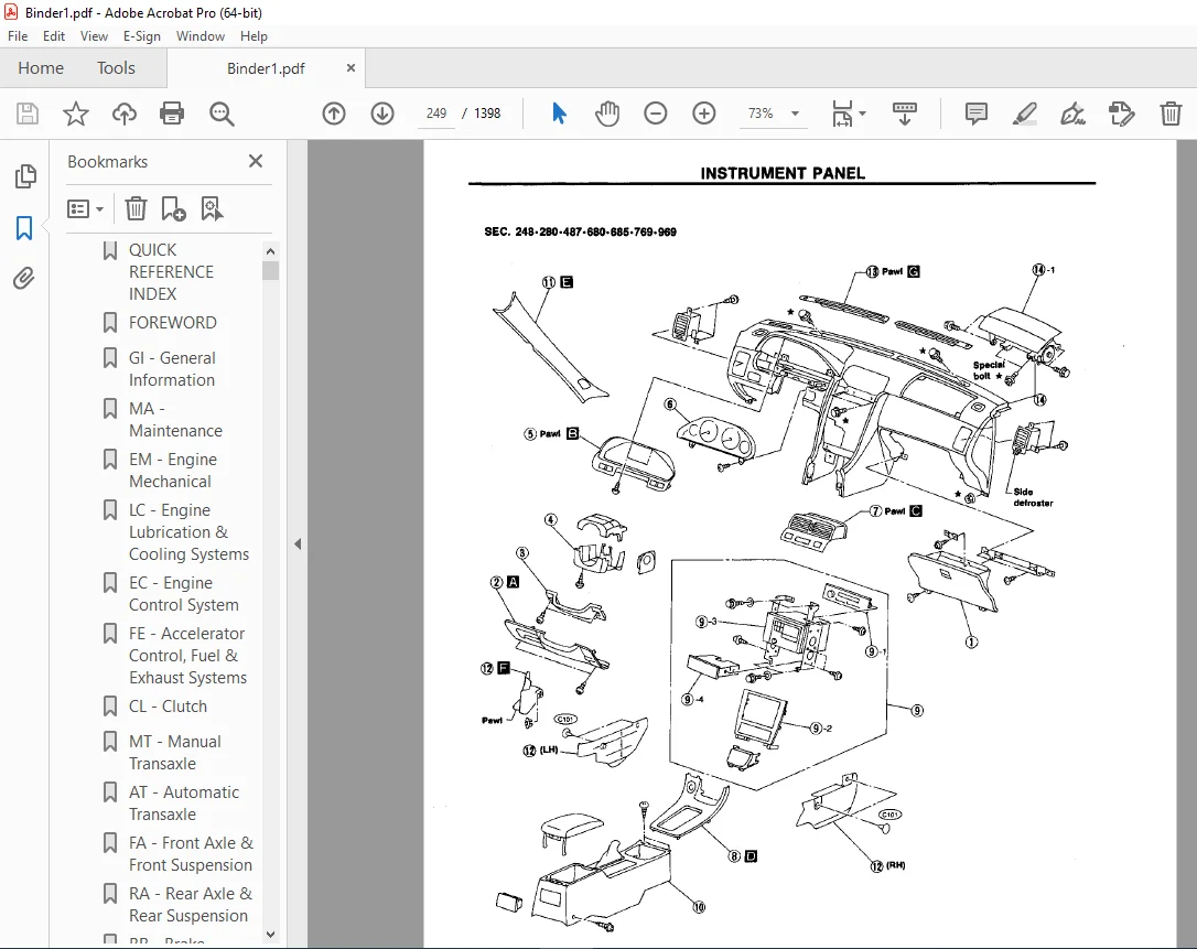
IMAGES PREVIEW OF THE MANUAL:
TABLE OF CONTENTS:
1995 NISSAN MAXIMA A32 Series Service Manual PDF DOWNLOAD
fwd...........................................................................................................   1
	Model Selection...........................................................................................   0
	QUICK REFERENCE INDEX.....................................................................................   1
	FOREWORD..................................................................................................   2
	GI - General Information..................................................................................   0
	MA - Maintenance..........................................................................................   0
	EM - Engine Mechanical....................................................................................   0
	LC - Engine Lubrication & Cooling Systems.................................................................   0
	EC - Engine Control System................................................................................   0
	FE - Accelerator Control, Fuel & Exhaust Systems..........................................................   0
	CL - Clutch...............................................................................................   0
	MT - Manual Transaxle.....................................................................................   0
	AT - Automatic Transaxle..................................................................................   0
	FA - Front Axle & Front Suspension........................................................................   0
	RA - Rear Axle & Rear Suspension..........................................................................   0
	BR - Brake System.........................................................................................   0
	ST - Steering System......................................................................................   0
	BF - Body.................................................................................................   0
	HA - Heater & Air Conditioner.............................................................................   0
	EL - Electrical System....................................................................................   0
	IDX - Alphabetical Index..................................................................................   1
	Foldout...................................................................................................   0
	Quick Reference Chart.....................................................................................   3
at............................................................................................................   4
	QUICK REFERENCE INDEX.....................................................................................   4
	TABLE OF CONTENTS.........................................................................................   4
	PREPARATION AND PRECAUTIONS...............................................................................   5
		Special Service Tools.................................................................................   5
		Commercial Service Tools..............................................................................   8
		Service Notice........................................................................................   9
		Supplemental Restraint System "AIR BAG"...............................................................  10
	DESCRIPTION...............................................................................................  11
		Cross-sectional View..................................................................................  11
		Hydraulic Control Circuit.............................................................................  12
		Shift  Mechanism......................................................................................  13
		Control System........................................................................................  15
	TROUBLE DIAGNOSIS.........................................................................................  17
		Contents..............................................................................................  17
		A/T Electrical Parts Location.........................................................................  40
		Wiring Diagram - AT -.................................................................................  42
		Self Diagnosis........................................................................................  49
			DTC P0720 VEHICLE SPEED SENSOR A/T (REVOLUTION SENSOR) CIRCUIT CHECK..............................  54
			VEHICLE SPEED SENSOR MTR CIRCUIT CHECK............................................................  56
			DTC P1705 THROTTLE POSITION SENSOR CIRCUIT CHECK..................................................  58
			DTC P0750 SHIFT SOLENOID VALVE A CIRCUIT CHECK....................................................  60
			DTC P0755 SHIFT SOLENOID VALVE B CIRCUIT CHECK....................................................  62
			DTC P1760 OVERRUN CLUTCH SOLENOID VALVE CIRCUIT CHECK.............................................  64
			DTC P0740 TORQUE CONVERTER CLUTCH SOLENOID VALVE CIRCUIT CHECK....................................  66
			DTC P0710 A/T FLUID TEMPERATURE SENSOR CIRCUIT AND A/T CONTROL UNIT POWER SOURCE CIRCUIT CHECK....  68
			DTC P0725 ENGINE SPEED SIGNAL CIRCUIT CHECK.......................................................  71
			DTC P0745 LINE PRESSURE SOLENOID VALVE CIRCUIT CHECK..............................................  73
			DTC P0705 INHIBITOR, OVERDRIVE AND THROTTLE POSITION SWITCH CIRCUIT CHECK.........................  75
			DTC P0731 IMPROPER SHIFTING TO 1ST GEAR POSITION..................................................  80
			DTC P0732 IMPROPER SHIFTING TO 2ND GEAR POSITION..................................................  82
			DTC P0733 IMPROPER SHIFTING TO 3RD GEAR POSITION..................................................  84
			DTC P0734 IMPROPER SHIFTING TO 4TH GEAR POSITION OR IMPROPER TORQUE CONVERTER CLUTCH OPERATION....  86
	TROUBLE DIAGNOSIS - A/T Shift Lock System................................................................. 118
		Contents.............................................................................................. 118
		Shift Lock System Electrical Parts Location........................................................... 119
		Wiring Diagram - SHIFT -.............................................................................. 120
	ON-VEHICLE SERVICE........................................................................................ 128
		Control Valve Assembly and Accumulator................................................................ 128
		Revolution Sensor Replacement......................................................................... 129
		Inhibitor Switch Adjustment........................................................................... 129
		Control Cable Adjustment.............................................................................. 130
		Differential Side Oil Seal Replacement................................................................ 130
	REMOVAL AND INSTALLATION.................................................................................. 131
		Removal............................................................................................... 131
		Installation.......................................................................................... 131
	MAJOR OVERHAUL............................................................................................ 133
	DISASSEMBLY............................................................................................... 136
	REPAIR FOR COMPONENT PARTS................................................................................ 150
		Manual Shaft.......................................................................................... 150
		Oil Pump.............................................................................................. 152
		Control Valve Assembly................................................................................ 156
		Control Valve Upper Body.............................................................................. 164
		Control Valve Lower Body.............................................................................. 168
		Reverse Clutch........................................................................................ 170
		High Clutch........................................................................................... 173
		Forward Clutch and Overrun Clutch..................................................................... 177
		Low & Reverse Brake................................................................................... 183
		Rear Internal Gear, Forward Clutch Hub and Overrun Clutch Hub......................................... 185
		Output Shaft, Idler Gear, Reduction Gear and Bearing Retainer......................................... 189
		Band Servo Piston Assembly............................................................................ 194
		Final Drive - RE4F04A................................................................................. 199
		Final Drive - RE4F04V................................................................................. 203
	ASSEMBLY.................................................................................................. 208
		Assembly 1............................................................................................ 208
		Adjustment 1.......................................................................................... 208
		Assembly 2............................................................................................ 213
		Adjustment 2.......................................................................................... 219
		Assembly 3............................................................................................ 221
	SERVICE DATA AND SPECIFICATIONS (SDS)..................................................................... 227
		General Specifications................................................................................ 227
		Specifications and Adjustments........................................................................ 227
bf............................................................................................................ 236
	QUICK REFERENCE INDEX.....................................................................................   0
	TABLE OF CONTENTS......................................................................................... 236
	GENERAL SERVICING......................................................................................... 238
		Precautions........................................................................................... 238
		Supplemental Restraint System "AIR BAG"............................................................... 238
		Circuit Breaker Inspection............................................................................ 238
		Clip and Fastener..................................................................................... 238
	BODY END.................................................................................................. 241
		Body Front End........................................................................................ 241
		Body Rear End and Opener.............................................................................. 243
		Trunk Lid Opening/Wiring Diagram - TLID -............................................................. 245
	DOOR...................................................................................................... 246
		Front Door............................................................................................ 246
		Rear Door............................................................................................. 247
	INSTRUMENT PANEL.......................................................................................... 248
	INTERIOR AND EXTERIOR..................................................................................... 251
		Interior.............................................................................................. 251
		Exterior.............................................................................................. 255
	SEAT...................................................................................................... 260
		Front Seat............................................................................................ 260
		Power Seat/Wiring Diagram - SEAT - ................................................................... 261
		Heated Seat........................................................................................... 262
		Heated Seat/Wiring Diagram - HSEAT -.................................................................. 263
		Rear Seat............................................................................................. 264
	SEAT BELT................................................................................................. 265
		Front Seat Belt....................................................................................... 265
		Rear Seat Belt........................................................................................ 266
	SUNROOF................................................................................................... 267
		Wiring Diagram - SROOF -.............................................................................. 271
	WINDSHIELD AND WINDOWS.................................................................................... 272
		Windshield and Rear Window............................................................................ 272
	MIRROR.................................................................................................... 273
		Door Mirror........................................................................................... 273
		Wiring Diagram - MIRROR -............................................................................. 274
		Wiring Diagram - H/MIRR............................................................................... 275
	BODY ALIGNMENT............................................................................................ 276
		Engine Compartment.................................................................................... 276
		Underbody............................................................................................. 278
	SUPPLEMENTAL RESTRAINT SYSTEM (SRS)....................................................................... 280
		Precautions for SRS "Air Bag" Service................................................................. 280
		Special Service Tools................................................................................. 280
		Commercial Service Tool............................................................................... 280
		Description........................................................................................... 281
		SRS Componenet Parts Location and Caution Labels...................................................... 282
		Caution Labels........................................................................................ 283
		Maintenance Items..................................................................................... 284
		Removal and Installation - Diagnosis Sensor Unit...................................................... 285
		Removal - Air Bag Module and Spiral Cable............................................................. 285
		Removal - Front Passenger Air Bag Module.............................................................. 287
		Installation - Air Bag and Spiral Cable............................................................... 288
		Installation - Front Passenger Air Bag Module......................................................... 289
		Disposal of Air Bag Module............................................................................ 289
	TROUBLE DIAGNOSIS - Supplemental Restraint System (SRS)................................................... 293
		Schematic............................................................................................. 293
		Wiring Diagram - SRS -................................................................................ 294
		Self-diagnosis........................................................................................ 296
		Diagnostic Procedure 1................................................................................ 301
		Diagnostic Procedure 2................................................................................ 301
		Diagnostic Procedure 3................................................................................ 302
		Collision Diagnosis................................................................................... 303
br............................................................................................................ 304
	QUICK REFERENCE INDEX.....................................................................................   0
	TABLE OF CONTENTS......................................................................................... 304
	PRECAUTIONS AND PREPARATION............................................................................... 305
		Precautions........................................................................................... 305
		Commercial Service Tools.............................................................................. 305
	BRAKE HYDRAULIC LINE/CONTROL VALVE........................................................................ 306
		Brake Hydraulic Line.................................................................................. 306
		Dual Proportioning Valve.............................................................................. 307
	CHECK AND ADJUSTMENT...................................................................................... 308
		Checking Brake Fluid Level............................................................................ 308
		Checking Brake Line................................................................................... 308
		Changing Brake Fluid.................................................................................. 308
		Bleeding Brake System................................................................................. 308
	BRAKE PEDAL AND BRACKET................................................................................... 309
		Removal and Installation.............................................................................. 309
		Inspection............................................................................................ 309
		Adjustment............................................................................................ 309
	MASTER CYLINDER........................................................................................... 310
		Removal............................................................................................... 310
		Disassembly........................................................................................... 310
		Inspection............................................................................................ 311
		Assembly.............................................................................................. 311
		Installatioin......................................................................................... 311
	BRAKE BOOSTER/VACUUM HOSE................................................................................. 312
		Brake Booster......................................................................................... 312
		Vacuum Hose........................................................................................... 313
	FRONT DISC BRAKE.......................................................................................... 314
		Pad Replacement....................................................................................... 314
		Removal............................................................................................... 315
		Disassembly........................................................................................... 315
		Inspection - Caliper.................................................................................. 316
		Inspection - Rotor.................................................................................... 316
		Assembly.............................................................................................. 317
		Installation.......................................................................................... 317
	REAR DISC BRAKE........................................................................................... 318
		Pad Replacement....................................................................................... 318
		Removal............................................................................................... 320
		Disassembly........................................................................................... 320
		Inspection - Caliper.................................................................................. 321
		Inspection - Rotor.................................................................................... 322
		Assembly.............................................................................................. 322
		Installation.......................................................................................... 323
	PARKING BRAKE CONTROL..................................................................................... 324
		Removal and Installation.............................................................................. 324
		Inspection............................................................................................ 325
		Adjustment............................................................................................ 325
	ANTI-LOCK BRAKE SYSTEM.................................................................................... 326
		Purpose............................................................................................... 326
		Operation............................................................................................. 326
		ABS Hydraulic Circuit................................................................................. 326
		System Components..................................................................................... 327
		System Description.................................................................................... 327
		Removal and Installation.............................................................................. 328
		Wiring Diagram - ABS -................................................................................ 330
	TROUBLE DIAGNOSES......................................................................................... 334
		Contents.............................................................................................. 334
		Component Parts and Harness Connector Location........................................................ 344
	SERVICE DATA AND SPECIFICATIONS (SDS)..................................................................... 366
		General Specifications................................................................................ 366
		Inspection and Adjustment............................................................................. 366
cl............................................................................................................ 367
	QUICK REFERENCE INDEX.....................................................................................   0
	TABLE OF CONTENTS......................................................................................... 367
	PRECAUTIONS AND PREPARATION............................................................................... 368
		Precautions........................................................................................... 368
		Special Service Tools................................................................................. 368
	CLUTCH SYSTEM - Hydraulic Type............................................................................ 369
	INSPECTION AND ADJUSTMENT................................................................................. 370
		Adjusting Clutch Pedal................................................................................ 370
		Bleeding Procedure.................................................................................... 370
	HYDRAULIC CLUTCH CONTROL.................................................................................. 372
		Clutch Master Cylinder................................................................................ 372
		Operating Cylinder.................................................................................... 373
	CLUTCH RELEASE MECHANISM.................................................................................. 374
	CLUTCH DISC AND CLUTCH COVER.............................................................................. 375
		Clutch Disc........................................................................................... 375
		Clutch Cover and Flywheel............................................................................. 376
	SERVICE DATA AND SPECIFICATIONS (SDS)..................................................................... 377
		General Specifications................................................................................ 377
		Inspection and Adjustment............................................................................. 377
ec............................................................................................................ 378
	QUICK REFERENCE INDEX.....................................................................................   0
	TABLE OF CONTENTS......................................................................................... 378
	PRECAUTIONS AND PREPARATION............................................................................... 380
		Supplemental Restraint System "AIR BAG"............................................................... 380
		Precautions for On-Board Diagnostic (OBD) System of  Engine and A/T................................... 380
		Engine Fuel & Emission Control System................................................................. 381
		Precautions........................................................................................... 382
	ENGINE AND EMISSION CONTROL OVERALL SYSTEM................................................................ 384
		Circuit Diagram....................................................................................... 384
		System Diagram........................................................................................ 385
		ECCS Component Parts Location......................................................................... 387
		Vacuum Hose Drawing................................................................................... 390
		System Chart.......................................................................................... 391
	ENGINE AND EMISSION BASIC CONTROL SYSTEM DESCRIPTION...................................................... 392
		Multiport Fuel Injection (MFI) System................................................................. 392
		Electronic Ignition (EI) System....................................................................... 394
		Air Conditioner Cut Control........................................................................... 395
		Fuel Cut Control (at no load & high engine speed)..................................................... 396
	EVAPORATIVE EMISSION SYSTEM - For California Models....................................................... 397
		Description........................................................................................... 397
		Inspection............................................................................................ 397
	EVAPORATIVE EMISSION SYSTEM - For Non-California Models................................................... 399
		Description........................................................................................... 399
		Inspection............................................................................................ 399
	POSITIVE CRANKCASE VENTILATION............................................................................ 401
		Description........................................................................................... 401
		Inspection............................................................................................ 401
	BASIC SERVICE PROCEDURE................................................................................... 402
		Fuel Pressure Release................................................................................. 402
		Fuel Pressure Check................................................................................... 402
		Injector Removal and Installation..................................................................... 403
		Fast Idle Cam (FIC) Inspection and Adjustment......................................................... 404
		Direct Ignition System - How to Check Idle Speed and Ignition Timing.................................. 405
		Idle Speed/Ignition System - How to Check Idle Speed and Ignition Timing.............................. 406
		Idle Speed/Ignition Timing/Idle Mixture Ratio Adjustment.............................................. 407
	ON-BOARD DIAGNOSTIC SYSTEM DESCRIPTION.................................................................... 413
		Introduction.......................................................................................... 413
		Two Trip Detection Logic.............................................................................. 413
		Diagnostic Trouble Code (DTC)......................................................................... 413
		Freeze Frame Data..................................................................................... 415
		Malfunction Indicator Lamp (MIL)...................................................................... 415
		OBD System Operation Chart............................................................................ 420
		Consult............................................................................................... 425
		Generic Scan Tool (GST)............................................................................... 436
	TROUBLE DIAGNOSIS - General Description................................................................... 438
		Introduction.......................................................................................... 438
		Work Flow............................................................................................. 439
		Description for Work Flow............................................................................. 440
		Diagnostic Worksheet.................................................................................. 441
		Alphabetical & P No. Index for DTC.................................................................... 442
		Diagnostic Trouble Code (DTC) Chart................................................................... 443
		Fail-Safe Chart....................................................................................... 454
		Basic Inspection...................................................................................... 455
		Symptom Matrix Chart.................................................................................. 458
		Consult Reference Value in Data Monitor Mode.......................................................... 461
		Major Sensor Reference Graph in Data Monitor Mode..................................................... 463
		ECM Terminals and Reference Value..................................................................... 465
	TROUBLE DIAGNOSIS FOR POWER SUPPLY........................................................................ 472
		Main Power Supply and Ground Circuit.................................................................. 472
	DTC 11, Camshaft Position Sensor (CMPS) (PHASE) (DTC: P0340).............................................. 476
	DTC 12, Mass Air Flow Sensor (MAFS) (DTC: P0100).......................................................... 480
	DTC 13, Engine Coolant Temperature Sensor (ECTS) (DTC: P0115)............................................. 485
	DTC 14, Vehicle Speed Sensor (VSS) (DTC: P0500)........................................................... 489
	DTC 21, Ignition Signal (DTC: P1320)...................................................................... 493
	DTC 25, Idle Air Control Valve (IACV) - Auxiliary Air Control (AAC) Valve (DTC: P0505).................... 500
	DTC 31, Engine Control Module (ECM)-ECCS Control Module (DTC: P0605)...................................... 504
	DTC 32, EGR Function (DTC: P0400)......................................................................... 506
	DTC 33, Front Heated Oxygen Sensor (Front HO2S) (Left bank) (DTC: P0150).................................. 516
	DTC 34, Knock Sensor (KS) (DTC: P0325).................................................................... 521
	DTC 35, EGR Temperature Sensor (DTC: P1401)............................................................... 524
	DTC 36, EGRC-BPT Valve Function (DTC: P0402).............................................................. 528
	DTC 37, 38, Closed Loop Control (DTC: P0130, P0150)....................................................... 530
	DTC 41, Intake Air Temperature Sensor (DTC: P0110)........................................................ 531
	DTC 42, Fuel Temperature Sensor (P0180)................................................................... 536
	DTC 43, Throttle Position Sensor (DTC: P0120)............................................................. 539
	DTC 47, Crankshaft Position Sensor (CKPS) (REF) (DTC: P1335).............................................. 544
	DTC 53, Front Heated Oxygen Sensor (Front HO2S) (Right bank) (DTC: P0130)................................. 548
	DTC 54, A/T Control (DTC: P0600).......................................................................... 553
	DTC 63 - 71, No. 6 - 1 Cylinder Misfire, Multiple Cylinder Misfire (DTC: P0306 - P0300)................... 557
	DTC 72, 73, Three Way Catalyst Function (DTC: P0420, P0430)............................................... 561
	DTC 76, Fuel Injection System Function (Right bank) (DTC: P0170).......................................... 564
	DTC 77, Rear Heated Oxygen Sensor (Rear HO2S) (DTC: P0136)................................................ 569
	DTC 82, Crankshaft Position Sensor (CKPS) (POS) (DTC: P0335).............................................. 574
	DTC 84, A/T Diagnosis Communication Line (DTC: P1605)..................................................... 579
	DTC 86, Fuel Injection System Function (Left bank) (DTC: P0173)........................................... 582
	DTC 87, Canister Control Solenoid Valve (DTC: P0443)...................................................... 587
	DTC 91, Front Heated Oxygen Sensor Heater (Right bank) (DTC: P0135)....................................... 592
	DTC 95, Crankshaft Position Sensor (CKPS) (POS) (DTC: P1336).............................................. 595
	DTC 98, Engine Coolant Temperature (ECT) Sensor (DTC: P0125).............................................. 600
	DTC 101, Front Heated Oxygen Sensor Heater (Left bank) (DTC: P0155)....................................... 605
	DTC 103, Park/Neutral Position Switch (DTC: P0705)........................................................ 608
	DTC 105, EGR (and Canister) Control Solenoid Valve (DTC: P1400)........................................... 612
	DTC 108, Canister Purge Control Valve (DTC: P0443)........................................................ 616
	TROUBLE DIAGNOSIS FOR NON-DETECTABLE ITEMS................................................................ 621
		Injector.............................................................................................. 621
		Start Signal.......................................................................................... 625
		Fuel Pump Control..................................................................................... 627
		Cooling Fan Control................................................................................... 634
		Front Engine Mounting Control......................................................................... 642
		Power Steering Oil Pressure Switch.................................................................... 645
		IACV-FICD Solenoid Valve.............................................................................. 649
		Electrical Load Signal................................................................................ 653
		MIL & Data Link Connectors............................................................................ 657
	SERVICE DATA AND SPECIFICATIONS (SDS)..................................................................... 658
		General Specifications................................................................................ 658
		Inspection and Adjustment............................................................................. 658
el............................................................................................................ 660
	QUICK REFERENCE INDEX.....................................................................................   0
	TABLE OF CONTENTS......................................................................................... 660
	PRECAUTIONS............................................................................................... 663
		Supplemental Restraint System "AIR BAG"............................................................... 663
	HARNESS CONNECTOR......................................................................................... 664
		Description........................................................................................... 664
	STANDARDIZED RELAY........................................................................................ 665
		Description........................................................................................... 665
	POWER SUPPLY ROUTING...................................................................................... 667
		Wiring Diagram - POWER -.............................................................................. 667
		Schematic............................................................................................. 677
		Fuse.................................................................................................. 678
		Fusible Link.......................................................................................... 678
	BATTERY................................................................................................... 679
		How to Handle Battery................................................................................. 679
		Service Data and Specifications (SDS)................................................................. 682
	STARTING SYSTEM........................................................................................... 683
		System Description.................................................................................... 683
		Wiring Diagram - START -.............................................................................. 685
		Construction.......................................................................................... 689
		Removal and Installation.............................................................................. 689
		Pinion/Clutch Check................................................................................... 690
		Service Data and Specifications (SDS)................................................................. 690
	CHARGING SYSTEM........................................................................................... 691
		System Description.................................................................................... 691
		Wiring Diagram - CHARGE -............................................................................. 692
		Construction.......................................................................................... 693
		Removal and Installation.............................................................................. 693
		Trouble Diagnoses..................................................................................... 694
		Service Data and Specifications (SDS)................................................................. 695
	COMBINATION SWITCH........................................................................................ 696
		Combination Switch/Check.............................................................................. 696
		Combination Switch/Replacement........................................................................ 697
		Steering Switch/Check................................................................................. 698
	HEADLAMP.................................................................................................. 699
		System Description (For USA).......................................................................... 699
		Wiring Diagram - H/LAMP -............................................................................. 700
		System Description (For Canada)....................................................................... 702
		Wiring Diagram - DTRL -............................................................................... 703
		Operation (Daytime light system for Canada)........................................................... 706
		Schematic............................................................................................. 706
		Trouble Diagnoses (For USA)........................................................................... 707
		Trouble Diagnoses (for Canada)........................................................................ 708
		Bulb Replacement...................................................................................... 710
		Aiming Adjustment..................................................................................... 710
	EXTERIOR LAMP............................................................................................. 712
		Back-up Lamp/Wiring Dagram - TAIL/L -................................................................. 712
		Clearance, License, Tail and Stop Lamps/Wiring Diagram - BACK/L -..................................... 713
		Front Fog Lamp/System Description..................................................................... 716
		Front Fog Lamp/Wiring Diagram F/FOG -................................................................. 717
		Turn Signal and Hazard Warning Lamps/System Description............................................... 719
		Turn Signal and Hazard Warning Lamps/Wirin gdiagram - TURN -.......................................... 720
		Turn Signal and Hazard Warning Lamps/Trouble Diagnoses................................................ 723
		Cornering Lamp/System Description..................................................................... 724
		Cornering LampWiring Diagram - CORNER -............................................................... 725
		Combination Flasher Unit Check........................................................................ 727
		Bulb Specifications................................................................................... 727
	INTERIOR LAMP............................................................................................. 728
		Illumination/System Description....................................................................... 728
		Spot and Trunk Room Lamps/System Description.......................................................... 729
		Illumination/Wiring Diagram - ILL -................................................................... 730
		Spot and Trunk Room Lamp/Wiring Diagram - INT/L -..................................................... 733
	METERS AND GAUGES......................................................................................... 734
		System Description.................................................................................... 734
		Combination Meter..................................................................................... 735
		Speedometer, Tachometer, Temp. and Fuel Gauges/Wiring Diagram - METER -............................... 736
		Inspection/Fuel Gauge and Water Temperature Gauge..................................................... 738
		Fuel Tank Gauge Unit Check............................................................................ 739
		Fuel Warning Lamp Sensor Check........................................................................ 739
		Thermal Transmitter Check............................................................................. 739
		Oil Pressure Switch Check............................................................................. 739
		Vehicle Speed Sensor Signal Check..................................................................... 740
	WARNING LAMPS............................................................................................. 741
		Wiring Diagram - WARN -............................................................................... 741
		Schematic............................................................................................. 744
		Diode Check........................................................................................... 745
	WIPER AND WASHER.......................................................................................... 746
		System Description.................................................................................... 746
		Front Wiper and Washer/Wiring Diagram - WIPER -....................................................... 748
		Installation.......................................................................................... 750
		Wiper Linkage......................................................................................... 750
		Washer Nozzle Adjustment.............................................................................. 751
		Check Valve........................................................................................... 751
	HORN, CIGARETTE LIGHTER, CLOCK............................................................................ 753
		Wiring Diagram - HORN -............................................................................... 753
	REAR WINDOW DEFOGGER...................................................................................... 755
		Wiring Diagram - DEF -................................................................................ 755
		Filament Check........................................................................................ 756
		Filament Repair....................................................................................... 757
	AUDIO AND POWER ANTENNA................................................................................... 758
		Audio/System Description.............................................................................. 758
		Audio/Wiring Diagram - AUDIO -........................................................................ 759
		Power Antenna/System Description...................................................................... 764
		Power Antenna/Wiring Diagram - P/ANT -................................................................ 765
		Trouble Diagnoses..................................................................................... 766
		Location of Antenna................................................................................... 768
		Antenna Rod Replacement............................................................................... 769
		Window Antenna Repair................................................................................. 770
	AUTOMATIC SPEED CONTROL DEVICE (ASCD)..................................................................... 771
		Component Parts and Harness Connector Location........................................................ 771
		System Description.................................................................................... 772
		Wiring Diagram - ASCD -............................................................................... 774
		Schematic............................................................................................. 779
		Trouble Diagnoses..................................................................................... 780
	IVMS (LAN) - SYSTEM DESCRIPTION........................................................................... 798
		Overall Description................................................................................... 798
		Component Parts Location.............................................................................. 800
		System Diagram........................................................................................ 801
		Sleep/Wake-up Control................................................................................. 802
		Fail-safe System...................................................................................... 803
	IVMS (LAN) - TROUBLE DIAGNOSES SYSTEM..................................................................... 804
		Work Flow............................................................................................. 804
		Consult............................................................................................... 805
		On-board Diagnosis.................................................................................... 813
		On-board Diagnosis - Mode I (IVMS communication diagnosis)............................................ 814
		On-board Diagnosis - Mode II (Switch monitor)......................................................... 816
		On-board Diagnosis - Mode III (Power door lock operation.............................................. 818
		On-board Diagnosis - Mode IV (Power window monitor)................................................... 820
	IVMS (LAN) - TROUBLE DIAGNOSES............................................................................ 822
		Body Control Module (BCM)............................................................................. 822
		Local Control Units (LCU's)........................................................................... 825
		Main Power Supply, Ground and Communication Circuits/Wiring Diagram - COMM - ......................... 833
		Power Supply and Ground Circuit Check................................................................. 836
	POWER WINDOW - IVMS....................................................................................... 838
		Component Parts and Harness Connector Location........................................................ 838
		System Description.................................................................................... 839
		Wiring Diagram - WINDOW -............................................................................. 840
		Schematic............................................................................................. 844
		Trouble Diagnoses..................................................................................... 845
	POWER DOOR LOCK - IVMS.................................................................................... 849
		Component Parts and Harness Connector Location........................................................ 849
		System Description.................................................................................... 850
		Wiring Diagram - D/LOCK -............................................................................. 851
		Schematic............................................................................................. 855
		Trouble Diagnoses..................................................................................... 856
	MULTI-REMOTE CONTROL SYSTEM - IVMS........................................................................ 862
		System Description.................................................................................... 862
		Wiring Diagram - MULTI -.............................................................................. 864
		Schematic............................................................................................. 871
		Trouble Diagnoses..................................................................................... 872
		Replacing Remote Controller or Multi-Remote Control Unit (LCU05)...................................... 876
	TIME CONTROL SYSTEM - IVMS................................................................................ 877
		System Description.................................................................................... 877
		Wiring Diagram - TIME -............................................................................... 880
		Trouble Diagnoses..................................................................................... 887
	THEFT WARNING SYSTEM - IVMS............................................................................... 901
		Component Parts and Harness Connector Location........................................................ 901
		Description........................................................................................... 902
		System Description.................................................................................... 903
		Wiring Diagram - THEFT -.............................................................................. 906
		Schematic............................................................................................. 913
		Trouble Diagnoses..................................................................................... 915
	ILLUMINATION - IVMS....................................................................................... 932
		System Description.................................................................................... 932
		Wiring Diagram - SW/ILL -............................................................................. 933
		Trouble Diagnoses..................................................................................... 934
	INTERIOR LAMP ON-OFF CONTROL - IVMS....................................................................... 935
		System Description.................................................................................... 935
		Wiring Diagram - ROOM/L............................................................................... 936
		Trouble Diagnoses..................................................................................... 937
	STEP LAMP - IVMS.......................................................................................... 938
		System Description.................................................................................... 938
		Wiring Diagram - STEP/L -............................................................................. 939
		Trouble Diagnoses..................................................................................... 941
	LOCATION OF ELECTRICAL UNITS.............................................................................. 942
		Engine Compartment.................................................................................... 942
		Passenger Compartment................................................................................. 943
		Luggage Compartment................................................................................... 944
	HARNESS LAYOUT............................................................................................ 945
		Outline............................................................................................... 945
		Engine Room Harness................................................................................... 946
		Main Harness.......................................................................................... 949
		Engine Control Harness................................................................................ 951
		Body Harness.......................................................................................... 953
		Body No. 2 Harness and Tail Harness................................................................... 955
		Room Lamp Harness..................................................................................... 956
		Air Bag Harness....................................................................................... 957
		Door Harness (LH side)................................................................................ 958
		Door Harness (RH side)................................................................................ 959
	SUPER MULTIPLE JUNCTION (SMJ).............................................................................   0
		Terminal Arrangement..................................................................................   1
	HYBRID ELECTRIC CONTROL UNIT (HEC)........................................................................   3
		Construction and Terminal Arrangement.................................................................   3
	JOINT CONNECTOR (J/C).....................................................................................   4
		Terminal Arrangement..................................................................................   4
em............................................................................................................ 960
	QUICK REFERENCE INDEX.....................................................................................   0
	TABLE OF CONTENTS......................................................................................... 960
	PRECAUTIONS............................................................................................... 961
		Parts Requiring Angular Tightening.................................................................... 961
		Supplemental Restraint System "AIR BAG"............................................................... 961
		Liquid Gasket Application Procedure................................................................... 961
	PREPARATION............................................................................................... 962
		Special Service Tools................................................................................. 962
		Commercial Service Tools.............................................................................. 963
	OUTER COMPONENT PARTS..................................................................................... 965
	COMPRESSION PRESSURE...................................................................................... 968
		Measurement of Compression Pressure................................................................... 968
	OIL PAN................................................................................................... 969
		Removal............................................................................................... 969
		Installation.......................................................................................... 973
	TIMING CHAIN.............................................................................................. 976
		Removal............................................................................................... 977
		Inspection............................................................................................ 984
		Installation.......................................................................................... 985
	OIL SEAL REPLACEMENT...................................................................................... 990
	CYLINDER HEAD............................................................................................. 993
		Removal............................................................................................... 994
		Disassembly........................................................................................... 994
		Inspection............................................................................................ 996
		Assembly..............................................................................................1001
		Installation..........................................................................................1001
	VALVE CLEARANCE...........................................................................................1006
		Checking..............................................................................................1006
		Adjusting.............................................................................................1007
	ENGINE REMOVAL............................................................................................1010
		Removal...............................................................................................1011
		Installation..........................................................................................1012
	CYLINDER BLOCK............................................................................................1013
		Disassembly...........................................................................................1014
		Inspection............................................................................................1014
		Assembly..............................................................................................1021
	SERVICE DATA AND SPECIFICATIONS (SDS).....................................................................1024
		General Specifications................................................................................1024
		Inspection and Adjustment.............................................................................1024
fa............................................................................................................1032
	QUICK REFERENCE INDEX.....................................................................................   0
	TABLE OF CONTENTS.........................................................................................1032
	PRECAUTIONS AND PREPARATION...............................................................................1033
		Precautions...........................................................................................1033
		Special Service Tools.................................................................................1033
		Commercial Service Tools..............................................................................1034
	FRONT SUSPENSION SYSTEM...................................................................................1035
	ON-VEHICLE SERVICE........................................................................................1036
		Front Axle and Front Suspension Parts.................................................................1036
		Front Wheel Bearing...................................................................................1037
		Front Wheel Alignment.................................................................................1037
		Drive Shaft...........................................................................................1038
	FRONT AXLE................................................................................................1039
		Wheel Hub and Knuckle.................................................................................1039
		Drive Shaft...........................................................................................1043
	FRONT SUSPENSION..........................................................................................1051
		Coil Spring and Strut Assembly........................................................................1051
		Stabilizer Bar........................................................................................1052
		Transverse Link and Lower Ball Joint..................................................................1054
	SERVICE DATA AND SPECIFICATIONS (SDS).....................................................................1055
		General Specifications................................................................................1055
		Inspection and Adjustment.............................................................................1057
fe............................................................................................................1058
	QUICK REFERENCE INDEX.....................................................................................   0
	TABLE OF CONTENTS.........................................................................................1058
	PREPARATION/ACCELERATOR CONTROL SYSTEM....................................................................1059
		Special Service Tool..................................................................................1059
		Adjusting Accelerator Wire............................................................................1059
	FUEL SYSTEM...............................................................................................1060
		Evaporation Shut Valve Inspection.....................................................................1060
	EXHAUST SYSTEM............................................................................................1061
foldout.......................................................................................................1062
	QUICK REFERENCE INDEX.....................................................................................   0
	ELECTRICAL SYSTEM.........................................................................................   0
	SUPER MULTIPLE JUNCTION (SMJ).............................................................................1062
		Terminal Arrangement..................................................................................1063
	HYBRID ELECTRIC CONTROL UNIT (HEC)........................................................................1065
		Construction and Terminal Arrangement.................................................................1065
	JOINT CONNECTOR (J/C).....................................................................................1066
		Terminal Arrangement..................................................................................1066
gi............................................................................................................1067
	QUICK REFERENCE INDEX.....................................................................................   0
	TABLE OF CONTENTS.........................................................................................1067
	PRECAUTIONS...............................................................................................1068
		Precautions for Supplemental Restraint System "AIR BAG"...............................................1068
		General Precautions...................................................................................1068
		Precautions for Multiport Fuel Injection System or ECCS Engine........................................1070
		Precautions for Three Way Catalyst....................................................................1070
		Engine Oils...........................................................................................1070
		Precautions for Fuel..................................................................................1071
	HOW TO USE THIS MANUAL....................................................................................1072
	HOW TO READ WIRING DIAGRAMS...............................................................................1074
		Sample/Wiring Diagram - EXAMPL -......................................................................1074
		Description...........................................................................................1076
		Wiring Diagram Codes (Cell Codes).....................................................................1082
	HOW TO PERFORM EFFICIENT DIAGNOSIS FOR AN ELECTRICAL INCIDENT.............................................1084
		Work Flow.............................................................................................1084
		Incident Simulation Tests.............................................................................1085
		Circuit Inspection....................................................................................1089
	HOW TO FOLLOW FLOW CHART IN TROUBLE DIAGNOSES.............................................................1095
	CONSULT CHECKING SYSTEM...................................................................................1098
		Function and System Application.......................................................................1098
		Lithium Battery Replacement...........................................................................1098
		Checking Equipment....................................................................................1098
	IDENTIFICATION INFORMATION................................................................................1099
		Model Variation.......................................................................................1099
		Identification Number.................................................................................1100
		Dimensions............................................................................................1102
		Wheels and Tires......................................................................................1102
	LIFTING POINTS AND TOW TRUCK TOWING.......................................................................1103
		Preparation...........................................................................................1103
		Board-on Lift.........................................................................................1103
		Garage Jack and Safety Stand..........................................................................1104
		2-pole Lift...........................................................................................1105
		Tow Truck Towing......................................................................................1106
	TIGHTENING TORQUE OF STANDARD BOLTS.......................................................................1107
	SAE J1930 TERMINOLOGY LIST................................................................................1108
		SAE J1930 Terminology List............................................................................1108
ha............................................................................................................1112
	QUICK REFERENCE INDEX.....................................................................................   0
	TABLE OF CONTENTS.........................................................................................1112
	MANUAL AND AUTO...........................................................................................1114
		PRECAUTIONS AND PREPARATION...........................................................................1114
			Supplemental Restraint System "AIR BAG"...........................................................1114
			Precautions for Working with HFC-134a (R-134a)....................................................1114
			General Refrigerant Precautions...................................................................1114
			Precautions for Refrigerant Connection............................................................1115
			Precautions for Servicing Compressor..............................................................1116
			Special Service Tools.............................................................................1116
			HFC-134a (R-134a) Service Tools and Equipment.....................................................1117
			Precautions for Service Equipment.................................................................1119
		DESCRIPTION...........................................................................................1121
			Refrigeration Cycle...............................................................................1121
			V-6 Variable Displacement Compressor..............................................................1122
			Component Layout..................................................................................1126
			Discharge Air Flow................................................................................1127
	MANUAL....................................................................................................1128
		DESCRIPTION...........................................................................................1128
			Control Operation.................................................................................1128
		TROUBLE DIAGNOSES.....................................................................................1129
			Contents..........................................................................................1129
	MANUAL AND AUTO...........................................................................................1140
		TROUBLE DIAGNOSES.....................................................................................1140
			Performance Test Diagnoses........................................................................1140
			Performance Chart.................................................................................1142
			Trouble Diagnoses for Abnormal Pressure...........................................................1143
	MANUAL....................................................................................................1147
		TROUBLE DIAGNOSES.....................................................................................1147
			Wiring Diagram - A/C, M...........................................................................1150
	AUTO......................................................................................................1171
		DESCRIPTION...........................................................................................1171
			Introduction......................................................................................1171
			Features..........................................................................................1171
			Control Operation.................................................................................1171
		TROUBLE DIAGNOSES.....................................................................................1173
			Contents..........................................................................................1173
			Wiring Diagram - A/C, A -.........................................................................1202
		SYSTEM DESCRIPTION....................................................................................1227
			Overview of Control System........................................................................1227
			Control System Input Components...................................................................1228
			Control System Automatic Amplifier (Auto amp.)....................................................1230
			Control System Output Components..................................................................1231
	MANUAL AND AUTO...........................................................................................1239
		SERVICE PROCEDURES....................................................................................1239
			R-134a Service Procedure..........................................................................1239
			Maintenance of Lubricant Quantity in Compressor...................................................1241
			Compressor Clutch.................................................................................1241
			Refrigerant Lines.................................................................................1243
			Compressor Mounting...............................................................................1244
			Belt Tension......................................................................................1244
			Fast Idle Control Device (FICD)...................................................................1244
			Compressor........................................................................................1245
			Compressor Clutch.................................................................................1245
	MANUAL ...................................................................................................1248
		SERVICE AND PROCEDURE.................................................................................1248
			Overhaul - Push Control Unit Assembly.............................................................1248
	MANUAL AND AUTO...........................................................................................1249
		SERVICE DATA AND SPECIFICATIONS (SDS).................................................................1249
			General Specifications............................................................................1249
			Inspection and Adjustment.........................................................................1249
idx...........................................................................................................1250
	QUICK REFERENCE INDEX.....................................................................................   0
lc............................................................................................................1257
	QUICK REFERENCE INDEX.....................................................................................   0
	TABLE OF CONTENTS.........................................................................................1257
	PRECAUTIONS AND PREPARATION...............................................................................1258
		The Supplemental Restraint System "AIR BAG"...........................................................1258
		Special Service Tools.................................................................................1258
		Liquid Gasket Application Procedure...................................................................1259
	ENGINE LUBRICATION SYSTEM.................................................................................1260
		Lubrication Circuit...................................................................................1260
		Oil Pressure Check....................................................................................1261
		Oil Pump..............................................................................................1261
	ENGINE COOLING SYSTEM.....................................................................................1264
		Cooling Circuit.......................................................................................1264
		System Check..........................................................................................1265
		Water Pump............................................................................................1265
		Thermostat............................................................................................1269
		Radiator..............................................................................................1270
		Cooling Fan Control System............................................................................1270
	SERVICE DATA AND SPECIFICATIONS (SDS).....................................................................1271
		Engine Lubrication System.............................................................................1271
		Engine Cooling System.................................................................................1271
ma............................................................................................................1272
	QUICK REFERENCE INDEX.....................................................................................   0
	TABLE OF CONTENTS.........................................................................................1272
	PRECAUTIONS AND PREPARATION...............................................................................1273
		Supplemental Restraint System "AIR BAG"...............................................................1273
		Special Service Tool..................................................................................1274
	GENERAL MAINTENANCE.......................................................................................1275
	PERIODIC MAINTENANCE......................................................................................1276
		Schedule 1............................................................................................1277
		Schedule 2............................................................................................1278
	RECOMMENDED FLUIDS AND LUBRICANTS.........................................................................1279
		Fluids and Lubricants.................................................................................1279
		SAE Viscosity Number..................................................................................1279
	ENGINE MAINTENANCE........................................................................................1280
		Checking Drive Belts..................................................................................1280
		Changing Engine Coolant...............................................................................1281
		Checking Fuel Lines...................................................................................1283
		Changing Fuel Filter..................................................................................1283
		Changing Air Cleaner Filter...........................................................................1284
		Changing Engine Oil...................................................................................1284
		Changing Oil Filter...................................................................................1284
		Changing Spark Plugs..................................................................................1285
		Checking Vapor Lines..................................................................................1286
	CHASSIS AND BODY MAINTENANCE..............................................................................1287
		Checking Exhaust System...............................................................................1287
		Checking Clutch Fluid Level and Leaks.................................................................1287
		Checking M/T Oil......................................................................................1287
		Changing M/T Oil......................................................................................1287
		Changing A/T Fluid....................................................................................1288
		Changing A/T Fluid....................................................................................1288
		Balancing Wheels......................................................................................1288
		Tire Rotation.........................................................................................1289
		Checking Brake Fluid Level and Leaks..................................................................1289
		Checking Brake Lines and Cables.......................................................................1289
		Checking Disc Brake...................................................................................1289
		Checking Steering Gear and Linkage....................................................................1290
		Checking Power Steering Fluid and Lines...............................................................1290
		Lubricating Locks, Hinges and Hood Latches............................................................1291
		Checking Seat Belts, Buckles, Retractors, Anchors and Adjusters.......................................1291
	SERVICE DATA AND SPECIFICATIONS (SDS).....................................................................1292
		Engine Maintenance....................................................................................1292
		Chassis and Body Maintenance..........................................................................1292
mt............................................................................................................1293
	QUICK REFERENCE INDEX.....................................................................................   0
	TABLE OF CONTENTS.........................................................................................1293
	PREPARATION...............................................................................................1294
		Special Service Tools.................................................................................1294
		Commercial Service Tools..............................................................................1296
	ON-VEHICLE SERVICE/REMOVAL AND INSTALLATION...............................................................1297
		Replacing Oil Seal....................................................................................1297
		Check of Position Switch..............................................................................1298
		Viscous Coupling Check................................................................................1298
		Removal...............................................................................................1298
		Installation..........................................................................................1299
	TRANSAXLE GEAR CONTROL....................................................................................1300
	MAJOR OVERHAUL............................................................................................1301
		Case Components.......................................................................................1301
		Gear Components.......................................................................................1302
		Shift Control Components..............................................................................1303
	DISASSEMBLY...............................................................................................1304
	REPAIR FOR COMPONENT PARTS................................................................................1307
		Input Shaft and Gears.................................................................................1308
		Mainshaft and Gears...................................................................................1313
		Final Drive...........................................................................................1317
		Shift Control Components..............................................................................1321
		Case Components.......................................................................................1321
	ADJUSTMENT................................................................................................1322
		Input Shaft End Play and Differential Side Bearing Preload............................................1322
		Mainshaft Bearing Preload.............................................................................1322
	ASSEMBLY..................................................................................................1325
	SERVICE DATA AND SPECIFICATIONS (SDS).....................................................................1329
		General Specifications................................................................................1329
		Inspection and Adjustment.............................................................................1329
ra............................................................................................................1333
	QUICK REFERENCE INDEX.....................................................................................   0
	TABLE OF CONTENTS.........................................................................................1333
	PRECAUTIONS AND PREPARATION...............................................................................1334
		Precautions...........................................................................................1334
		Special Service Tools.................................................................................1334
		Commercial Service Tools..............................................................................1334
	REAR SUSPENSION SYSTEM....................................................................................1335
	ON-VEHICLE SERVICE........................................................................................1336
		Rear Axle and Rear Suspension Parts...................................................................1336
		Rear Wheel Bearing....................................................................................1336
		Rear Wheel Alignment..................................................................................1337
	REAR AXLE.................................................................................................1338
		Wheel Hub.............................................................................................1338
	REAR SUSPENSION...........................................................................................1340
		Removal and Installation..............................................................................1341
		Coil Spring and Shock Absorber........................................................................1341
		Torsion Beam, Lateral Link and Control Rod............................................................1343
	SERVICE DATA AND SPECIFICATIONS (SDS).....................................................................1344
		General Specifications................................................................................1344
		Inspection and Adjustment.............................................................................1344
st............................................................................................................1345
	QUICK REFERENCE INDEX.....................................................................................   0
	TABLE OF CONTENTS.........................................................................................1345
	PRECAUTIONS AND PREPARATION...............................................................................1346
		Precautions...........................................................................................1346
		Special Service Tools.................................................................................1346
		Commercial Service Tools..............................................................................1347
	ON-VEHICLE SERVICE........................................................................................1348
		Checking Steering Wheel Play..........................................................................1348
		Checking Neutral Position on Steering Wheel...........................................................1348
		Front Wheel Turning Angle.............................................................................1348
		Checking Gear Housing Movement........................................................................1348
		Checking and Adjusting Drive Belts (For power steering)...............................................1349
		Checking Fluid Level..................................................................................1349
		Checking Fluid Leakage................................................................................1349
		Bleeding Hydraulic System.............................................................................1349
		Checking Steering Wheel Turning Force (For power steering)............................................1350
		Checking Hydraulic System.............................................................................1351
	STEERING WHEEL AND STEERING COLUMN........................................................................1352
		Removal and Installation..............................................................................1352
		Disassembly and Assembly..............................................................................1354
		Inspection............................................................................................1355
	POWER STEERING GEAR AND LINKAGE...........................................................................1356
		Removal and Installation..............................................................................1356
		Disassembly...........................................................................................1359
		Inspection............................................................................................1360
		Assembly..............................................................................................1360
		Adjustment............................................................................................1365
	POWER STEERING OIL PUMP...................................................................................1366
		Pre-disassembly Inspection............................................................................1366
		Disassembly...........................................................................................1367
		Inspection............................................................................................1367
		Assembly..............................................................................................1368
	SERVICE DATA AND SPECIFICATIONS (SDS).....................................................................1369
		General Specifications................................................................................1369
		Inspection and Adjustment.............................................................................1369
1995_MAXIMA_Body_Repair_Manual................................................................................1371
	1995 Nissan Maxima Body Repair Manual.....................................................................1371
	5A3295....................................................................................................1371
	Table of Contents.........................................................................................1371
DESCRIPTION:
1995 NISSAN MAXIMA A32 Series Service Manual PDF DOWNLOAD
FOREWORD
- This manual contains maintenance and repair procedures for the 1995 Nissan MAXIMA.
- In order to assure your safety and the efficient functioning of the vehicle, this manual should be read thoroughly.
- It is especially important that the PRECAUTIONS in the GI section be completely understood before starting any repair task.
- All information in this manual is based on the latest product information at the time of publication. The right is reserved to make changes in specifications ~nd methods at any time without notice.
IMPORTANT SAFETY NOTICE
- The proper performance of service is essential for both the safety of the technician and the efficient functioning of the vehicle.
- The service methods in this Service Manual are described in such a manner that the service may be performed safely and accurately.
- Service varies with the procedures used, the skills of the technician and the tools and parts available.
- Accordingly, anyone using service procedures, tools or parts which are not specifically recommended by NISSAN must first be completely satisfied that neither personal safety nor the vehicle’s safety will be jeopardized by the service method selected.
PLEASE NOTE:
- This is the same manual used by the dealers to diagnose and troubleshoot your vehicle
- You will be directed to the download page as soon as the purchase is completed. The whole payment and downloading process will take anywhere between 2-5 minutes
- Need any other service / repair / parts manual, please feel free to contact [email protected] . We still have 50,000 manuals unlisted
G.P