Description
1995 NISSAN STANZA ALTIMA U13 Series Service Manual PDF DOWNLOAD
FILE DETAILS:
1995 NISSAN STANZA ALTIMA U13 Series Service Manual PDF DOWNLOAD
Language : English
Pages : 1254
Downloadable :Yes
File Type : PDF
IMAGES PREVIEW OF THE MANUAL:


Contact us: [email protected]
https://vimeo.com/850039582?share=copy
DESCRIPTION:
1995 NISSAN STANZA ALTIMA U13 Series Service Manual PDF DOWNLOAD
FOREWORD
This manual contains maintenance and repair procedures for the 1995 Nissan STANZA ALTIMA. In order to assure your safety and the efficient functioning of the vehicle, this manual should be read thoroughly. It is especially important that the PRECAUTIONS in the GI section be completely understood before starting any repair task. All information in this manual is based on the latest product information at the time of publication. The right is reserved to make changes in specifications and methods at any time without notice.
PREPARATION AND SAFETY PRECAUTIONS:
• Before proceeding with disassembly, thoroughly clean the outside of the transaxle. It is important to prevent the internal parts from becoming contaminated by dirt or other foreign matter.
• Disassembly should be done in a clean work area.
• Use lint-free cloth or towels for wiping parts clean. Common shop rags can leave fibers that could interfere with the operation of the transaxle.
• Place disassembled parts in order for easier and proper assembly.
• All parts should be carefully cleaned with a general-purpose, non-flammable solvent before inspection or reassembly.
• Gaskets, seals, and O-rings should be replaced any time the transaxle is disassembled.
• When connecting ATF control unit harness connector, tighten bolt until the red projection is in line with the connector.
• The valve body contains precision parts and requires extreme care when parts are removed and serviced. Place disassembled valve body parts in order for easier and proper assembly. Care will also prevent springs and small parts from becoming scattered or lost.
• Properly installed valves, sleeves, plugs, etc. will slide along bores in the valve body under their own weight.
• Before assembly, apply a coat of recommended ATF to all parts. Apply petroleum jelly to protect O-rings and seals or hold bearings and washers in place during assembly. Do not use grease.
• Extreme care should be taken to avoid damage to O-rings, seals, and gaskets when assembling.
• Flush or replace ATF cooler if excessive foreign material is found in the oil pan or clogging the strainer. Refer to TROUBLE DIAGNOSES Remarks, AT-18.
• After overhaul, refill the transaxle with new ATF.
• When the ATF drain plug is removed, only some of the fluid is drained. Old ATF fluid will remain in the torque converter and ATF cooling system. Always follow the procedures under “Changing ATF Fluid” in the MA section when changing ATF fluid
TABLE OF CONTENTS:
1995 NISSAN STANZA ALTIMA U13 Series Service Manual PDF DOWNLOAD
fwd 1
Model Selection 0
QUICK REFERENCE INDEX 1
FOREWORD 2
GI – General Information 0
MA – Maintenance 0
EM – Engine Mechanical 0
LC – Engine Lubrication & Cooling Systems 0
EC – Engine Control System 0
FE – Accelerator Control, Fuel & Exhaust Systems 0
CL – Clutch 0
MT – Manual Transaxle 0
AT – Automatic Transaxle 0
FA – Front Axle & Front Suspension 0
RA – Rear Axle & Rear Suspension 0
BR – Brake System 0
ST – Steering System 0
RS – Restraint System 0
BT – Body & Trim 0
HA – Heater & Air Conditioner 0
EL – Electrical System 0
IDX – Alphabetical Index 1
Foldout 0
Quick Reference Chart 3
at 4
QUICK REFERENCE INDEX 0
TABLE OF CONTENTS 4
PREPARATION AND PRECAUTIONS 9
Special Service Tools 9
Commercial Service Tools 12
Service Notice 13
Precautions For Supplemental Restraint System “AIR BAG” 14
DESCRIPTION 15
Cross-sectional View 15
Hydraulic Control Circuit 16
Shift Mechanism 17
Construction 17
Function Of Clutch And Brake 17
Operation Of Clutch And Brake 18
Control System 19
A/T Control Unit Function 20
Input/Output Signal Of A/T Control Unit 20
TROUBLE DIAGNOSES 21
How to Perform Trouble Diagnoses for Quick and Accurate Repair 21
Work Flow 21
Information From Customer 22
Diagnostic Worksheet 23
Remarks 25
Fail-Safe 25
ATF Cooler Service 25
OBD-II Self-Diagnosis 25
Diagnosis by CONSULT 26
Notice 26
Self-Diagnostic Result Test Mode 26
Data Monitor Diagnostic Test Mode 27
Data Analysis 29
Preliminary Check 30
A/T Fluid Check 30
Fluid leakage check 30
Fluid condition check 30
Fluid level check 30
Road Test 30
Description 30
1 Check before engine is started 31
2 Check at idle 32
3 Cruise test 34
Cruise test – Part 1 37
Cruise test – Part 2 39
Cruise test – Part 3 40
Shift Schedule 41
Vehicle speed when shifting gears 41
Vehicle speed when performing lock-up 41
A/T Electrical Parts Location 42
Circuit Diagram for Quick Pinpoint Check 43
Wiring Diagram – AT – 44
Self-diagnosis 51
SELF-DIAGNOSTIC PROCEDURE WITH CONSULT 51
SELF-DIAGNOSTIC PROCEDURE WITH GENERIC SCAN TOOL (GST) 52
SELF-DIAGNOSTIC PROCEDURE WITHOUT CONSULT OR GST 52
Judgement Of Self-Diagnosis Code Indicated By OD Off Indicator Lamp 54
HOW TO ERASE DTC WITH CONSULT 56
HOW TO ERASE DTC WITH GENERIC SCAN TOOL 56
HOW TO ERASE DTC WITHOUT CONSULT OR GST 56
DTC P0720 Vehicle Speed Sensor – A/T (Revolution Sensor) Circuit Check 57
Vehicle Speed Sensor – Mtr Circuit Check 59
DTC P1705 Throttle Position Sensor Circuit Check 61
DTC P0750 Shift Solenoid Valve A Circuit Check 63
DTC P0755 Shift Solenoid Valve B Circuit Check 65
DTC P1760 Overrun Clutch Solenoid Valve Circuit Check 67
DTC P0740 Torque Converter Clutch Solenoid Valve Circuit Check 69
DTC P0710 Fluid Temperature Sensor Circuit And A/T Control Unit Power Source Circuit Checks 71
DTC P0725 Engine Speed Signal Circuit Check 74
DTC P0745 Line Pressure Solenoid Valve Circuit Check 76
DTC P0705 Inhibitor, Overdrive And Throttle Position Switch Circuit Checks 78
DTC P0731 Improper Shifting To 1st Gear Position 83
DTC P0732 Improper Shifting To 2nd Gear Position 85
DTC P0733 Improper Shifting To 3rd Gear Position 87
DTC P0734 Improper Shifting To 4th Gear Position Or Improper Torque Converter Clutch Operation 89
Diagnostic Procedures for Symptoms 93
Diagnostic Procedure 1 (SYMPTOM: OD Off indicator lamp does not come on for about 2 seconds when turning ignition switch to “ON”) 93
Diagnostic Procedure 2 (SYMPTOM: Engine cannot be started with selector lever in “P” or “N” position or engine can be started with selector lever in “D”, “2”, “1” or “R” position) 94
Diagnostic Procedure 3 (SYMPTOM: Vehicle moves when it is pushed forward or backward with selector lever in “P” position) 94
Diagnostic Procedure 4 (SYMPTOM: Vehicle moves forward or backward when selecting “N” position) 95
Diagnostic Procedure 5 (SYMPTOM: There is a large shock when changing from “N” to “R” position) 96
Diagnostic Procedure 6 (SYMPTOM: Vehicle does not creep backward when selecting “R” position) 97
Diagnostic Procedure 7 (SYMPTOM: Vehicle does not creep forward when selecting “D”, “2” or “1” position) 98
Diagnostic Procedure 8 (SYMPTOM: Vehicle cannot be started from D1 on Cruise test – Part1) 99
Diagnostic Procedure 9 (SYMPTOM: A/T does not shift from D1 to D2 at the specified speed A/T does not shift from D4 to D2 when depressing accelerator pedal fully at the specified speed) 100
Diagnostic Procedure 10 (SYMPTOM: A/T does not shift from D2 to D3 at the specified speed) 101
Diagnostic Procedure 11 (SYMPTOM: A/T does not shift from D3 to D4 at the specified speed A/T must be warm before D3 to D4 shift will occur) 102
Diagnostic Procedure 12 (SYMPTOM: A/T does not perform lock-up at the specified speed) 103
Diagnostic Procedure 13 (SYMPTOM: A/T does not hold lock-up condition for more than 30 seconds) 104
Diagnostic Procedure 14 (SYMPTOM: Lock-up is not released when accelerator pedal is released) 104
Diagnostic Procedure 15 (SYMPTOM: Engine speed does not smoothly return to idle when A/T is shifted from D4 to D3 Vehicle does not decelerate by engine brake when turning overdrive swithc OFF> Vehicle does not decelerate by enging brake when shifting A/T from “D” to “2”) 105
Diagnostic Procedure 16 (SYMPTOM: Vehicle does not start from D1 on Cruise test – Part 2) 106
Diagnostic Procedure 17 (SYMPTOM: Vehicle does not shift from D4 to D3 when changing overdrive switch to “OFF” position) 106
Diagnostic Procedure 18 (SYMPTOM: A/T does not shift from D3 to D2 when changin selector lever from “D” to “2” position) 107
Diagnostic Procedure 19 (SYMPTOM: A/T does not shift from 22 to 11 when changing selector lever from “2” to “1” position) 107
Diagnostic Procedure 20 (SYMPTOM: Vehicle does not decelerate by engine brake when shifting from 22 (12) to 11) 107
Electrical Components Inspection 108
Inspection Of A/T Control Unit 108
A/T Control Unit Inspection Table 108
Solenoid Valves And Fluid Temperature Sensor 112
Solenoid valves 112
Fluid temperature sensor 112
Overdrive Switch 113
Inhibitor Switch 113
Revolution Sensor 114
Dropping Resistor 114
Throttle Position Switch 114
Closed throttle position switch (idle position) 114
Wide open throttle position switch 114
Final Check 115
Stall Testing 115
Judgement of Stall Test 116
Pressure Testing 118
Line pressure test procedure 118
Judgement Of Line Pressure Test 119
Symptom Chart 120
TROUBLE DIAGNOSES – A/T Shift Lock System 123
Shift Lock System Electrical Parts Location 123
Wiring Diagram – SHIFT – 124
Diagnostic Procedure 124
Key Interlock Cable 129
Removal 129
Installation 129
Shift Lock Control Unit Inspection 130
Shift Lock Control Unit Inspection Table 130
Component Check 131
Shift Lock Solenoid 131
Park Position Switch 131
Stop Lamp Switch 131
ON-VEHICLE SERVICE 132
Control Valve Assembly anad Accumulator 132
Removal 132
Installation 133
Revolution Sensor Replacement 133
Inhibitor Switch Adjustment 133
Control Cable Adjustment 134
Differential Side Oil Seal Replacement 134
REMOVAL AND INSTALLATION 135
Removal 135
Installation 136
MAJOR OVERHAUL 138
Oil Channel 141
DISASSEMBLY 142
REPAIR FOR COMPONENT PARTS 156
Manual Shaft 156
Removal 156
Inspection 157
Installation 157
Oil Pump 158
Disassembly 159
Inspection 160
Oil pump housing, oil pump cover, inner gear and outer gear 160
Side clearance 160
Seal ring clearance 160
Assembly 161
Control Valve Assembly 162
Disassembly 162
Inspection 165
Lower and upper bodies 165
Oil strainer 165
Shift solenoid valves A and B, line pressure solenoid valve, torque converter clutch solenoid valve and overrun clutch solenoid valve 165
Oil cooler relief valve sprin 166
Assembly 166
Control Valve Upper Body 170
Disassembly 171
Inspection 171
Valve springs 171
Control valves 171
Assembly 172
1-2 accumulator valve 172
Retainer plate 173
Control Valve Lower Body 174
Disassembly 175
Inspection 175
Valve springs 175
Control valves 175
Assembly 175
Retainer plate 175
Reverse Clutch 176
Disassembly 176
Inspection 177
Reverse clutch snap ring, spring retainer and return springs 177
Reverse clutch drive plates 177
Reverse clutch dish plates 177
Reverse clutch piston 177
Assembly 177
High Clutch 179
Disassembly 179
Inspection 180
High clutch snap ring, spring retainer and return springs 180
High clutch drive plates 180
Hight clutch piston 181
Seal ring clearance 181
Assembly 181
Forward Clutch and Overrun Clutch 183
Disassembly 184
Inspection 185
Snap rings, spring retainer and return springs 185
Forward clutch and overrun clutch drive plates 185
Forward clutch and overrun clutch dish plates 185
Forward clutch drum 186
Overrun clutch piston 186
Assembly 186
Low & Reverse Brake 189
Disassembly 189
Inspection 190
Low & reverse clutch snap ring, spring retainer and reutrn springs 190
Low & reverse brake drive plate 190
Assembly 190
Rear Internal Gear, Forward Clutch Hub and Overrun Clutch Hub 192
Disassembly 192
Inspection 193
Rear internal gear, forward clutch hub and overrun clutch hub 193
End bearings and forward one-way clutch 194
Assembly 194
Output Shaft, Idler Gear, Reduction Gear and Bearing Retainer 196
Disassembly 196
Inspection 198
Output shaft, idler gear and reduction gear 198
Bearing 198
Seal ring clearance 198
Assembly 199
Band Servo Piston Assembly 201
Disassembly 201
Inspection 203
Pistons, retainers and piston stem 203
Return springs 203
Assembly 203
Final Drive – RE4F04A 206
Disassembly 206
Inspection 207
Gear, washer, shaft and case 207
Bearings 207
Assembly 208
Final Drive – RE4F04V 210
Disassembly 210
Inspection 211
Gear, washer, shaft and case 211
Viscous coupling 212
Bearings 212
Assembly 212
ASSEMBLY 215
Assembly 1 215
Adjustment 1 215
Differential Side Bearing Preload 215
Reduction Gear Bearing Preload 217
Output Shaft End Play 219
Assembly 2 221
Adjustment 2 227
Total End Play 227
Assembly 3 229
SERVICE DATA AND SPECIFICATIONS (SDS) 235
General Specifications 235
Specifications and Adjustments 235
Vehicle Speed When Shifting Gears 235
Vehicle Speed When Performing Lock-Up 235
Stall Revolution 235
Line Pressure 235
Control Valves 236
Control valve return springs 236
Clutches And Brakes 237
Final Drive 239
Differential side gear clearance 239
Differential side gear thrust washers 239
RE4F04V 239
Differential side bearing preload adjusting shims 240
RE4F04V 240
Bearing preload – RE4F04V 240
Turning torque – RE4F04V 240
Clutch and brake return springs – RE4F04V 240
Planetary Carrier And Oil Pmup 241
Input Shaft 241
Reduction Gear 241
Turning torque 241
Reduction gear bearing adjusting shims 242
Reverse Clutch End Play 242
Thrust washers for adjusting reverse clutch drum end play 242
Accumulator 242
O-ring 242
Return spring 242
Band Servo 243
Return spring 243
Removal and Installation 243
Output Shaft 243
Seal ring clearance 243
End play 243
Output shaft adjusting shims 243
Bearing Retainer 243
Seal ring clearance 243
Total End Play 243
Bearing race for adjusting total end play 243
br 244
QUICK REFERENCE INDEX 0
TABLE OF CONTENTS 244
PRECAUTIONS AND PREPARATION 246
Precautions 246
Supplemental Restraint System “Air Bag” 246
Brake System 246
Commercial Service Tools 247
CHECK AND ADJUSTMENT 248
Checking Brake Fluid Level 248
Checking Brake Line 248
Changing Brake Fluid 248
AIR BLEEDING 249
Bleeding Procedure 249
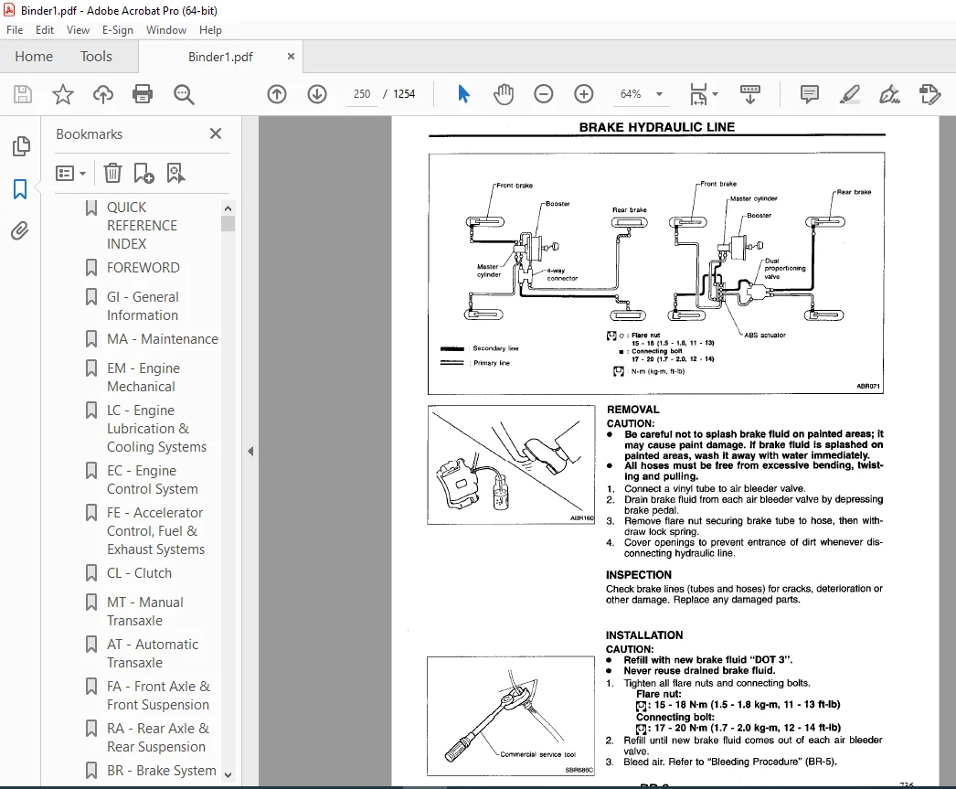
BRAKE HYDRAULIC LINE 250
Removal 250
Inspection 250
Installation 250
CONTROL VALVE 251
Proportioning Valve 251
Inspection 251
Removal (Separated type) 251
Installation (Separated type) 252
Removal And Installation (Built-in type) 252
BRAKE PEDAL AND BRACKET 253
Removal and Installation 253
Inspection 253
Adjustment 253
MASTER CYLINDER 255
Removal 255
Disassembly 255
Inspection 256
Assembly 256
Installation 257
BRAKE BOOSTER 258
On-vehicle Service 258
Operating Check 258
Airtight Check 258
Removal 258
Inspection 259
Output Rod Length Check 259
Installation 259
VACUUM HOSE 260
Removal and Installation 260
Inspection 260
Hoses And Connectors 260
Check Valve 260
FRONT DISC BRAKE 261
Pad Replacement 261
Removal 262
Disassembly 263
Inspection – Caliper 263
Cylinder Body 263
Piston 263
Slide Pin, Pin Bolt And Pin Boot 263
Inspection – Rotor 263
Runout 263
Thickness 264
Assembly 264
Installation 264
REAR DRUM BRAKE 265
Removal 265
Inspection – Wheel Cylinder 267
Wheel Cylinder Overhaul 267
Inspection – Drum 267
Inspection – Lining 268
Installation 268
REAR DISC BRAKE 270
Pad Replacement 270
Removal 272
Disassembly 272
Inspection – Caliper 273
Cylinder Body 273
Torque Member 273
Piston 273
Slide Pin, Pin Bolt And Pin Boot 273
Inspection – Rotor 274
Runout 274
Thickness 274
Assembly 274
Installation 276
PARKING BRAKE CONTROL 277
Removal and Installation 277
Inspection 277
Adjustment 278
ANTI-LOCK BRAKE SYSTEM 279
Purpose 279
Operation 279
System Description 280
Sensor 280
Control Module 280
Removal and Installation 281
Front Wheel Sensor 281
Rear Wheel Sensor 281
Control Module 282
Actuator 282
Actuator Relays 282
Wiring Diagram – ABS – 284
TROUBLE DIAGNOSES 288
How to Perform Trouble Diagnoses for Quick and Accurate Repair 288
Introduction 288
Self-diagnosis 289
Function 289
Self-diagnosis Procedure 289
How To Read Self-Diagnostic Results (Malfunction codes) 290
How To Erase Self-Diagnostic Results (Malfunction codes) 290
Malfunction Code/Symptom Chart 291
Component Parts and Harness Connector Location 292
Preliminary Check 293
Ground Circuit Check 294
Actuator Motor Ground 294
Control Module Ground 294
Relay Box Ground 294
Circuit Diagram for Quick Pinpoint Check 295
Diagnostic Procedure 1 (Not self-diagnostic item) 296
Diagnostic Procedure 2 (Not Self-diagnostic Item) 297
Diagnostic Procedure 3, Actuator Solenoid Valve (Malfunction code No 45, 41 or 55) 300
Diagnostic Procedure 4, Wheel Sensor Or Rotor 301
Diagnostic Procedure 5, Motor Relay Or Motor 303
Diagnostic Procedure 6, Solenoid Valve Relay 306
Diagnostic Procedure 7, Power Supply (Low voltage) 308
Diagnostic Procedure 8, Stop Lamp Switch Circuit 308
Diagnostic Procedure 9, Control Module 308
Electrical Components Inspection 309
Wheel Sensor 309
Motor Relay 309
Solenoid Valve Relay 309
SERVICE DATA AND SPECIFICATIONS (SDS) 310
General Specifications 310
Inspection and Adjustment 310
Disc Brake 310
Drum Brake 310
Brake Pedal 310
Parking Brake 310
bt 311
QUICK REFERENCE INDEX 0
TABLE OF CONTENTS 311
GENERAL SERVICING 313
Precautions 313
Supplemental Restraint System “AIR BAG” 313
Clip and Fastener 314
BODY END 317
Body Front End 317
Removal – Front bumper assembly 317
Body Rear End and Opener 319
Removal – Rear bumper assembly 319
DOOR 321
Front Door 321
Rear Door 322
INTRUMENT PANEL 323
Removal – Instrument panel assembly 323
INTERIOR TRIM 326
Side and Floor Trim 326
Door Trim 327
Roof Trim 328
Luggage Rooom Trim 329
EXTERIOR TRIM 330
Exterior 330
(1) Front hood insulator 331
(2) Cowl top grille and cowl top front sealing rubber 331
(3) Front windshield molding 331
Windshield upper and side molding 332
(4) Sunroof lid weatherstrip 332
(5) Body side drip weatherstrip 332
(6) Door weatherstrip 333
(7) Body side welt 333
(8) Door waist outside molding 333
(9) Front door corner cover 334
(10) Rear windshield molding 334
(11) Trunk lid weatherstrip 334
(12) Rear combination lamp 335
(13) Side guard molding 335
(14) Center mudguard 336
(15) Front door parting seal 336
SEAT 337
Front Seat 337
Rear Seat 338
SUNROOF 339
Removal 340
Sunroof Lid Assembly 340
Shade Asembly 340
Sunroof Assembly 340
Link & Wire Assembly 340
Adjustment 341
WINDSHIELD AND WINDOWS 342
Removal 342
Installation 342
Windshield and Rear Window 342
Repairing Water Leaks For Windshield 343
MIRROR 344
Door Mirror 344
Removal and Installation 344
Disassembly 344
Rearview Mirror 345
Removal 345
Installation 345
REAR AIR SPOILER 346
Rear Air Spoiler 346
BODY ALIGNMENT 347
Engine Compartment 347
Measurement 347
Measurement Points 348
Underbody 349
Measurement 349
Measurement Points 350
cl 351
QUICK REFERENCE INDEX 0
TABLE OF CONTENTS 351
PRECAUTONS AND PREPARATION 352
Precautions 352
Special Service Tools 352
CLUTCH SYSTEM – Hydraulic Type 353
INSPECTION AND ADJUSTMENT 354
Adjusting Clutch Pedal 354
For USA model only 355
Bleeding Procedure 355
HYDRAULIC CLUTCH CONTROL 356
Clutch Master Cylinder 356
Disassembly And Assembly 356
Inspection 357
Operating Cylinder 357
Inspection 357
CLUTCH RELEASE MECHANISM 358
Inspection 358
Lubrication 358
CLUTCH DISC AND CLUTCH COVER 359
Clutch Disc 359
Inspection 359
Installation 359
Clutch Cover and Flywheel 360
Inspection and Adjustment 360
Flywheel Inspection 360
Installation 360
SERVICE DATA AND SPECIFICATIONS (SDS) 361
General Specifications 361
Clutch Control System 361
Clutch Master Cylinder 361
Clutch Operating Cylinder 361
Clutch Disc 361
Clutch Cover 361
Inspection and Adjustment 361
Clutch Pedal 361
Clutch Disc 361
Clutch Cover 361
ec 362
QUICK REFERENCE INDEX 0
TABLE OF CONTENTS 362
PRECAUTIONS AND PREPARATION 367
Special Service Tool 367
Supplemental Restraint System “AIR BAG” 367
Precautions for On-Board Diagnostic (OBD) System of Engine and A/T 367
Engine Fuel & Emission Control System 368
Precautions 369
ENGINE AND EMISSION CONTROL OVERALL SYSTEM 371
Circuit Diagram 371
System Diagram 372
ECCS Component Parts Location 373
Vacuum Hose Drawing 375
System Chart 376
ENGINE AND EMISSION BASIC CONTROL SYSTEM DESCRIPTION 377
Multiport Fuel Injection (MFI) System 377
Input/Output Signal Line 377
Basic Multiport Fuel Injection System 377
Various Fuel Injection Increase/Decrease Compensation 377
Mixture Ratio Feedback Control 378
Open Loop Control 378
Mixture Ratio Self-Learning Control 378
Fuel Injection Timing 379
Sequential multiport fuel injection system 379
Simultaneous multiport fuel injection system 379
Fuel Shut-Off 379
Distributor Ignition (DI) System 379
Input/Output Signal Line 379
System Description 380
Air Conditioning Cut Control 380
Input/Output Signal Line 380
System Description 380
Fuel Cut Control (at no load & high engine speed) 381
Input/Output Signal Line 381
EVAPORATIVE EMISSION SYSTEM 382
Description 382
Inspection 382
Canister 382
Fuel Check Valve (With rollover valve) 383
Check valve operation 383
Rollover valve operation 383
Fuel Tank Vacuum Relief Valve 383
POSITIVE CRANKCASE VENTILATION 384
Description 384
Inspection 384
PCV (Positive Crankcase Ventilation) 384
Ventilation Hose 384
BASIC SERVICE PROCEDURE 385
Fuel Pressure Release 385
Fuel Pressure Check 385
Fuel Pressure Regulator Check 386
Injector Removal and Installation 386
Idle Speed/Ignition Timing/Idle Mixture Ratio Adjustment 387
Preparation 387
Overall inspection sequence 387
ON-BOARD DIAGNOSTIC SYSTEM DESCRIPTION 393
Introduction 393
Two Trip Detection Logic 393
Diagnostic Trouble Code (DTC) 393
How To Read DTC 393
How To Erase DTC 393
HOW TO ERASE DTC (With CONSULT) 393
HOW TO ERASE DTC (Without CONSULT) 394
Freeze Frame Data 394
Malfunction Indicator Lamp (MIL) 395
On-Board Diagnostic System Function 395
How To Switch Diagnostic Test Modes 396
Diagnostic Test Mode I – Bulb Check 397
Diagnostic Test Mode I – Maulfunction Warning 397
Diagnostic Test Mode II – Self-Diagnostic Results 397
How To Erase Diagnostic Test Mode II (Self-diagnostic results) 397
Diagnostic Text Mode II – Front Oxygen Sensor Monitor 398
OBD System Operation Chart 398
Relationship Between MIL, DTC, CONSULT And Detectable Items 398
Summary Chart 398
Relationship Between MIL, DTC, CONSULT And Driving Patterns For “Misfire” <Exhaust Quality Deterioration>, “Fuel Injection System” 399
Explanation For Driving Patterns For “Misfire <Exhaust Quality Deterioration>, “Fuel Injection System” 400
Relationship Between MIL, DTC, CONSULT And Driving Patters Except For “Misfire <Exhaust Quality Deterioration>”, “Fuel Injection System” 401
Explanation For Driving Patterns Except For “Misfire <Exhaust Quality Deterioration>”, “Fuel Injection System” 402
CONSULT 403
CONSULT Inspection Procedure 403
ECCS Component Parts/Control Systems Application 404
Function 405
Work Support Mode 405
Self-Diagnostic Mode 406
Data Monitor Mode 406
Active Test Mode 409
Function Test Mode 410
Freeze Frame Data 413
Real Time Diagnosis In Data Monitor Mode 414
Generic Scan Tool (GST) 415
Description 415
GST Inspection Procedure 415
Function 416
TROUBLE DIAGNOSIS – General Description 418
Introduction 418
Work Flow 419
Description for Work Flow 420
Diagnostic Worksheet 421
Worksheet Sample 421
Alphabetical & P No Index for DTC 422
Alphabetical Index For DTC 422
P No Index For DTC 422
Diagnostic Trouble Code (DTC) Chart 423
Engine Related Items 423
A/T Related Items (Be sure to erase the DTC stored in ECM after the A/T related repair) 431
Inspection Priority (Engine Related Items) 433
Fail-Safe Chart 434
Basic Inspection 435
Symptom Matrix Chart 438
CONSULT Reference Value in Data Monitor Mode 441
Major Sensor Reference Graph in Data Monitor Mode 444
ECM Terminals and Reference Value 446
Preparation 446
ECM Harness Connector Terminal Layout 446
ECM Inspection Table 447
TROUBLE DIAGNOSIS FOR POWER SUPPLY 452
Main Power Supply and Ground Circuit 452
DTC 11, Camshaft Position Sensor (CMPS) (DTC: P0340) 455
Diagnostic Trouble Code Confirmation Procedure 455
Diagnostic Procedure (Detectable Circuit) 457
Diagnostic Procedure (Non-Detectable Circuit) 458
Component Inspection 458
DTC 12, Mass Air Flow Sensor (MAFS) (DTC: P0100) 460
Diagnostic Trouble Code Confirmation Procedure 460
Overall Function Check 461
Diagnostic Procedure 463
Component Inspection 464
DTC 13, Engine Coolant Temperature Sensor (ECTS) (DTC: P01115) 465
Diagnostic Trouble Code Confirmation Procedure 465
Diagnostic Procedure 467
Component Inspection 468
DTC 14, Vehicle Speed Sensor (VSS) (DTC: P0500) 469
Overall Function Check 469
Diagnostic Trouble Code Confirmation Procedure 470
Diagnostic Procedure 472
DTC 21, Ignition Signal (DTC: P1320) 473
Component Description 473
Ignition coil & power transistor (Built into distributor) 473
Diagnostic Trouble Code Confirmation Procedure 473
Diagnostic Procedure 475
Component Inspection 477
Ingition coil 477
Power transistor 477
Resistor 478
DTC 25, Idle Air Control Valve (IACV) – Auxiliary Air Control (AAC) Valve (DTC: P0505) 479
System Description 479
Component Description 479
Diagnostic Trouble Code Confirmation Procedure 480
Diagnostic Procedure 482
Component Inspection 482
DTC 28, Cooling Fan (DTC: P1900) 483
System Description 483
Cooling fan control 483
Operation 483
On-board Diagnosis Logic 484
Overall Function Check 485
Diagnostic Procedure 487
Main 12 Causes Of Overheating 493
Component Inspection 494
Cooling fan relay -1 494
Cooling fan relays – 2 and -3 494
Cooling fan motors -1 and -2 494
DTC 31, Engine Control Module (ECM)-ECCS Control Module (DTC: P0605) 495
Diagnostic Trouble Code Confirmation Procedure 495
DTC 32, EGR Function (DTC: P0400) 497
System Description 497
Component Description 497
Exhaust gas recirculation (EGR) valve 497
EGR and canister control solenoid valve 497
On-board Diagnosis Logic 498
Overall Function Check 498
Diagnostic Procedure 502
Components Inspection 504
EGR valve 504
EGR & canister control solenoid valve 504
Canister 504
EGR temperature sensor 504
EGRC-BPT valve 504
DTC 33, Front Oxygen Sensor (Front O2S) (DTC: P0130) 505
Overall Function Check 505
Diagnostic Procedure 508
DTC 34, Knock Sensor (KS) (DTC: P0325) 510
Diagnostic Trouble Code Confirmation Procedure 510
Diagnostic Procedure 512
Component Inspection 512
DTC 35, EGR Temperature Sensor (DTC: P1401) 513
Diagnostic Trouble Code Confirmation Procedure 513
Diagnostic Procedure 516
Component Inspection 516
DTC 36, EGRC-BPT Valve Function (DTC: P0402) 517
System Description 517
On-Board Diagnosis Logic 517
Overall Function Check 517
Component Inspection 518
DTC 37, Closed Loop Control (DTC: P0130) 519
Overall Function Check 519
Diagnostic Procedure 519
DTC 41, Intake Air Temperature Sensor (DTC: P0110) 520
Diagnostic Trouble Code Confirmation Procedure 520
Diagnostic Procedure 523
Component Inspection 524
DTC 43, Throttle Position Sensor (DTC: P0120) 525
Overall Function Check 526
Diagnostic Procedure 528
Component Inspection 529
DTC 65 – 71, No 4 – 1 Cylinder Misfire, Multiple Cylinder Misfire (DTC: P0304 – P0300) 530
On-board Diagnosis Logic 530
Diagnostic Trouble Code Confirmation Procedure (Overall) 530
Diagnostic Procedure 531
Component Inspection 533
Ignition wires 533
DTC 72, Three Way Catalyst Function (DTC: P0420) 534
On-Board Diagnosis Logic 534
Overall Function Check 534
Diagnostic Procedure 536
DTC 76, Fuel Injection System Function (DTC: P0170) 537
On-Board Diagnosis Logic 537
Diagnostic Trouble Code Confirmation Procedure (Overall) 537
Diagnostic Procedure 540
DTC 77, Rear Heated oxygen Sensor (Rear HO2S) (DTC: P0136) 542
On-Board Diagnosis Logic 542
Overall Function Check 543
Diagnostic Procedure 545
Component Inspection 546
DTC 82, Crankshaft Position Sensor (CKPS) (OBD) (DTC: P0335) 547
Diagnostic Trouble Code Confirmation Procedure 547
Diagnostic Procedure 549
Component Inspection 550
DTC 84, A/T Diagnosis Communication Line (DTC: P1605) 551
Diagnostic Trouble Code Confirmation Procedure 551
DTC 95, Crankshaft Position Sensor (CKPS) (OBD) (DTC: P1336) 554
Diagnostic Trouble Code Confirmation Procedure 554
Diagnostic Procedure 556
Component Inspection 557
DTC 98, Engine Coolant Temperature (ECT) Sensor (DTC: P0125) 558
Overall Function Check 559
Diagnostic Procedure 561
Component Inspection 562
DTC 103, Park/Neutral Position Switch (DTC: P0705) 563
Overall Function Check 563
Diagnostic Procedure 565
Component Inspection 569
DTC 105, EGR and Canister Control Solenoid Valve (DTC: P1400) 570
Overall Function Check 570
Diagnostic Procedure 572
Component Inspection 573
DTC P0600 574
Diagnostic Trouble Code Confirmation Procedure 574
Overall Function Check 574
Diagnostic Procedure 576
TROUBLE DIAGNOSIS FOR NON-DETECTABLE ITEMS 577
Injector 577
Component Description 578
Diagnostic Procedure 578
Component Inspection 579
Start Signal 580
Diagnostic Procedure 581
Fuel Pump 582
System Description 582
Component Description 582
Diagnostic Procedure 584
Component Inspection 586
Fuel pump relay 586
Fuel pump 586
Power Steering Oil Pressure Switch 587
Component Description 588
Diagnostic Procedure 588
Component Inspection 589
Power steering oil pressure switch 589
IACV-Air Regulator 590
Component Description 590
Component Inspection 590
IACV-FICD Solenoid Valve 591
Component Description 592
Diagnostic Procedure 592
Componenet Inspection 594
IACV-FICD solenoid valve 594
Rear Window Defogger Signal 595
Diagnostic Procedure 596
MIL & DATA Link Connectors 597
SERVICE DATA AND SPECIFICATIONS (SDS) 598
General Specifications 598
Inspection and Adjustment 598
Ignition Coil 598
Mass Air Flow Sensor 598
Engine Coolant Temperature Sensor 598
EGR Temperature Sensor 598
Fuel Pump 598
IACV-AAC Valve 598
Injector 598
Resistor 598
Throttle Position Sensor 598
Calculated Load Value 599
Intake Air Temperature Sensor 599
Rear Heated Oxygen Sensor Heater 599
Crankshaft Position Sensor (OBD) 599
el 600
QUICK REFERENCE INDEX 0
TABLE OF CONTENTS 600
PRECAUTIONS 604
Supplemental Restraint System “AIR BAG” 604
HARNESS CONNECTOR 605
Description 605
STANDARDIZED RELAY 606
Description 606
POWER SUPPLY ROUTING 608
Schematic 608
Wiring Diagram – POWER – 609
Fuse 615
Fusible Link 615
Circuit Breaker Iinspection 615
BATTERY 616
How to Handle Battery 616
Methods Of Preventing Discharge 616
Checking Electrolyte Level 616
Specific Gravity Check 617
Hydrometer temperature correction 617
Charging The Battery 618
Memory Reset 618
Voltage chart 619
Service Data and Specifications (SDS) 619
STARTING SYSTEM 620
System Description 620
MT models for USA 620
M/T models for Canada 620
A/T models 620
Wiring Diagram – START – 622
M/T models for USA 622
M/T models for Canada 623
A/T models 624
Starter 625
Pinion/Clutch Check 627
Service Data and Specifications (SDS) 627
CHARGING SYSTEM 628
System Description 628
Wiring Diagram – CHARGE – 629
Trouble Diagnoses 630
CHARGING SYSTEM 631
Generator 631
Diode Check 632
Assembly 633
Service Data and Specifications (SDS) 634
COMBINATION SWITCH 635
Combination Switch/Check 635
Combination Switch/Replacement 636
Steering Switch/Check 637
HEADLAMP 638
System Description (For USA) 638
Low beam operation 638
High beam operation/flash-to-pass operation 638
Wiring Diagram (For USA) – H/LAMP – 639
Trouble Diagnoses (For USA) 640
System Description (For Canada) 641
Headlamp Operation 641
Daytime Light Operation 642
Operation (Daytime light system for Canada) 642
Schematic (For Canada) 643
Wiring Diagram (For Canada) – DTRL – 644
Trouble Diagnoses (For Canada) 647
Daytime Light Control Module Inspection Table 647
Bulb Replacement 649
Aiming Adjustment 649
Low Beam 649
Adjustment After Headlamp Assembly Replacement 650
EXTERIOR LAMP 651
Back-up Lamp/Wiring Diagram – BACK/L – 651
Clearance, License, Tail anad Stop Lamps/Wiring Diagram – TAIL/L – 652
Front Fog Lamp/System Description 655
Front Fog Lamp/Wiring Diagram – F/FOG – 656
Turn Signal and Hazard Warning Lamps/System Description 657
Turn Signal Operation 657
Hazard Lamp Operation 657
Turn Signal and Hazard Warning Lamps/Wiring Diagram – TURN – 658
Turn Signal and Hazard Warning Lamps/Trouble Diagnoses 660
Cornering Lamps/System Description 661
Cornering Lamp/Wiring Diagram – CORNER – 662
Combination Flasher Unit Check 663
Bulb Specifications 663
INTERIOR LAMP 664
Illumination/System Description 664
Illumination/Schematic 665
Illumination/Wiring Diagram – ILL – 666
Interior, Personal and Trunk Room Lamps/Wiring Diagram – INT/L – 669
METERS AND GAUGES 670
System Description 670
Combination Meter 671
Speedometer, Tachometer, Temp and Fuel Gauges/Wiring Diagram – METER – 672
Inspection/Fuel Gauge and Water Temperature Gauge 674
Inspection/Tachometer 675
Inspection/Speedometer and Vehicle Speed Sensor 676
Inspection/Speedometer and Fuse 677
Fuel Tank Gauge Unit Check 678
Fuel Warning Lamp Sensor Check 678
Thermal Transmitter Check 678
Oil Pressure Switch Check 679
Vehicle Speed Sensor Signal Check 679
WARNING LAMPS AND CHIME 680
Warning Lamps/Schematic 681
Warning Lamps/Wiring Diagram – WARN – 682
Warning Chime/System Description 685
Warning Chime/Wiring Diagram – CHIME – 686
Diode Check 687
Warning Chime Check 687
TIME CONTROL SYSTEM 688
System Description 688
Function 689
Circuit Diagram for Quick Pinpoint Check 690
Wiring Diagram – TIME – 691
Trouble Diagnoses 694
Symptom Chart 694
Preliminary Check 695
Preliminary check 1 695
Preliminary check 2 695
Preliminary check 3 695
Main Power Supply And Ground Circuit Check 696
Diagnostic Procedure 1 697
Diagnostic Procedure 2 698
Diagnostic Procedure 3 698
Diagnostic Procedure 4 699
Diagnostic Procedure 5 700
Diagnostic Procedure 6 701
Diagnostic Procedure 7 702
WIPER AND WASHER 703
System Description 703
Wiper Operation 703
Washer Operation 703
Front Wiper and Washer/Wiring Diagram – WIPER – 706
Installation 708
Washer Nozzle Adjustment 709
POWER WINDOW 710
System Description 710
Manual Operation 710
Auto Feature 711
Lock Feature 712
Component Layout 713
Wiring Diagram – WINDOW – 714
Trouble Diagnoses 716
POWER DOOR LOCK 717
System Description 717
Power Door Lock 717
Unlock 717
Lock 717
Circuit Diagram for Quick Pinpoint Check 717
Wiring Diagram – D/LOCK – 718
Door Lock Timer 720
MIRROR 721
Wiring Diagram – MIRROR – 721
SUNROOF 722
System Description 722
Power 722
Tilt And Slide Operation 722
If The Sunroof Does Not Close 722
Wiring Diagram – SROOF – 723
HORN, CIGARETTE LIGHTER, CLOCK 724
Wiring Diagram – HORN – 724
REAR WINDOW DEFOGGER 725
System Description 725
Wiring Diagram – DEF – 726
Filament Check 727
Filament Repair 728
AUDIO AND POWER ANTENNA 729
Audio/System Description 729
With Active Speaker Audio System 729
Without Active Speaker Audio System 729
Audio/Schematic 731
With Active Speaker Audio System 731
Audio/Wiring Diagram – AUDIO – 732
With Active Speaker Audio System 732
Without Active Speaker Audio System 735
Power Antenna/System Description 736
Location of Antenna 736
Power Antenna/Wiring Diagram – P/ANT – 737
Trouble Diagnoses 738
Antenna Rod Replacement 740
Window Antenna Repair 741
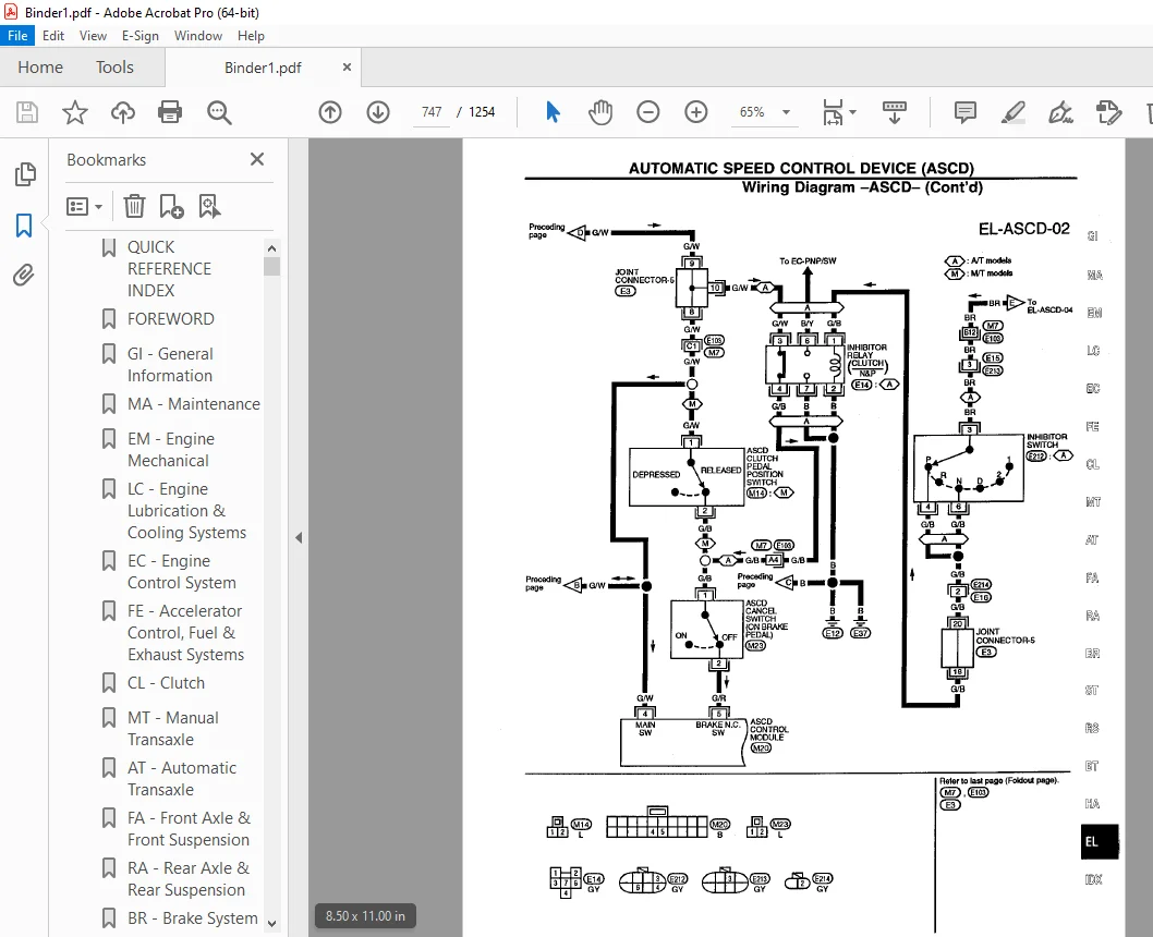
AUTOMATIC SPEED CONTROL DEVICE (ASCD) 742
System Description 742
Component Parts and Harness Connector Location 744
Schematic 745
Wiring Diagram – ASCD – 746
Trouble Diagnoses 751
Symptom Chart 751
Diagnostic Procedure 1 752
Diagnostic Procedure 2 754
Diagnostic Procedure 3 754
Diagnostic Procedure 4 754
Diagnostic Procedure 5 755
Diagnostic Procedure 6 756
Diagnostic Procedure 7 757
Diagnostic Procedure 8 758
ASCD Wire Adjustment 759
Electrical Components Inspection 760
ASCD actuator/ASCD pump 760
ASCD main switch 761
ASCD steering switch 761
ASCD cancel switch and stop lamp switch 761
ASCD clutch pedal position switch (For M/T models) 761
Inhibitor switch (For A/T models) 761
Vehicle speed sensor 762
THEFT WARNING SYSTEM 763
System Description 763
Theft Warning System Activation (Without key used to lock front doors) 763
Theft Warning System Activation (With key used to lock doors) 763
Theft Warning System Operation 764
Theft Warning System Deactivation 764
Component Parts and Harness Connector Location 765
Circuit Diagram for Quick Pinpoint Check 766
Wiring Diagram – THEFT – 768
Trouble Diagnoses 775
System Operation Check 775
Power Supply And Ground Circuit Check 777
Main power supply circuit check 777
Power supply circuit check for system cancel 777
Ground circuit check 777
Diagnostic Procedure 1 778
Diagnostic procedure 1-(1) 778
Diagnostic procedure 1-(2) 779
Diagnostic procedure 1-(3) 780
Diagnostic procedure 1-(4) 781
Diagnostic Procedure 2 782
Diagnostic Procedure 3 783
Diagnostic Procedure 4 784
Diagnostic Procedure 5 785
Diagnostic Procedure 6 786
Diagnostic Procedure 7 787
Diagnostic Procedure 8 788
Electrical Components Inspection 789
Door switches 789
Hood switch 789
Trunk room lamp switch 789
Key cylinder switch 790
Indicator lamp (security lamp) 790
Door unlock sensor 790
LOCATION OF ELECTRICAL UNITS 791
Engine Compartment 791
Passenger Compartment 792
HARNESS LAYOUT 793
Outline 793
Engine Room Harness 794
Passenger Compartment 796
Engine Compartment 794
Main Harness 798
Body Harness 800
Engine Control Harness 802
Engine Harness No 2 804
Room Lamp Harness 805
Air Bag Harness 806
Tail Harness 807
Door Harness (LH side) 808
Front 808
Rear 808
Door Harness (RH side) 809
Front 809
Rear 809
SUPER MULTIPLE JUNCTION (SMJ) 0
Installation 0
Terminal Arrangement 1
JOINT CONNECTOR (J/C) 2
Location 2
Terminal Arrangement 2
FUSE BLOCK/FUSIBLE LINK AND FUSE BOX 3
Fuse Arrangement 3
CONTROL MODULES 4
em 810
QUICK REFERENCE INDEX 0
TABLE OF CONTENTS 810
PRECAUTIONS 812
Precautions for Supplemental Restraint System “AIR BAG” 812
Parts Requiring Angular Tightening 812
Liquid Gasket Application Procedure 812
PREPARATION 813
Special Service Tools 813
Commercial Service Tools 816
OUTER COMPONENT PARTS 817
COMPRESSION PRESSURE 819
Measurement of Compression Pressure 819
OIL PAN 820
Removal 820
Installation 822
TIMING CHAIN 825
Liquid gasket application places 826
Removal 827
Upper Timing Chain 827
Lower Timing Chain 830
Inspection 830
Installation 830
Lower Timing Chain 831
Upper Timing Chain 831
OIL SEAL REPLACEMENT 834
Valve Oil Seal 834
Front Oil Seal 834
Rear Oil Seal 835
ACCEL-DRUM UNIT 836
CYLINDER HEAD 838
Removal and Installation 839
Disassembly 839
Inspection 839
Cylinder Head Distortion 839
Camshaft Visual Check 840
Camshaft Runout 840
Camshaft Cam Height 840
Camshaft Journal Clearance 840
Camshaft End Play 841
Camshaft Sprocket Runout 841
Valve Guide Clearance 841
Valve Guide Replacement 842
Valve Seats 843
Replacing Valve Seat For Service Parts 843
Valve Dimensions 843
Valve Spring 844
Squareness 844
Pressure 844
Valve Lifter And Valve Shim 844
Assembly 845
Valve Clearance 845
Checking 845
Adjusting 846
ENGINE REMOVAL 848
Removal 849
Installation 850
CYLINDER BLOCK 851
Disassembly 852
Piston And Crankshaft 852
Inspection 853
Piston And Piston Pin Clearance 853
Piston Ring Side Clearance 853
Piston Ring End Gap 853
Connecting Rod Bend And Torsion 854
Cylinder Block Distortion 854
Piston-To-Bore Clearance 854
Crankshaft 855
Bearing Clearance 856
Method A (Using bore gauge & micrometer) 856
Main bearing 856
Connecting rod bearing (Big end) 857
Method B (Using plastigage) 858
Connecting Rod Bushing Clearance (Small end) 858
Replacement Of Connecting Rod Bushing (Small end) 859
Flywheel/Drive Plate Runout 859
Assembly 859
Piston 859
Crankshaft 860
SERVICE DATA AND SPECIFICATIONS (SDS) 862
General Specifications 862
Compression Pressure 862
Inspection and Adjustment 862
Cylinder Head 862
Valve 862
Valve Spring 862
Valve Lifter 863
VALVE GUIDE 863
Valve Clearance Adjustment 864
Available shims 864
Valve Seat 865
Cylinder Block 866
Camshaft And Camshaft Bearing 867
Piston, Piston Ring And Piston Pin 868
Piston 868
Piston pin 868
Piston ring 868
Connecting Rod 868
Crankshaft 869
Bearing Clearance 870
Available Main Bearing 870
Standard 870
Undersize (service) 870
Available Connecting Rod Bearing 870
Standard 870
Undersize (service) 870
Miscellaneous Components 870
fa 871
QUICK REFERENCE INDEX 0
TABLE OF CONTENTS 871
PRECAUTIONS AND PREPARATION 872
Precautions 872
Special Service Tools 872
Commercial Service Tools 872
FRONT AXLE AND FRONT SUSPENSION 873
ON-VEHICLE SERVICE 874
Front Axle and Front Suspension Parts 874
Front Wheel Bearing 875
Front Wheel Alignment 875
Preliminary Inspection 876
Camber, Caster And Kingpin Inclination 876
Toe-In 876
Front Wheel Turning Angle 877
Drive Shaft 877
FRONT AXLE 878
Wheel Hub and Knuckle 879
Removal 879
Installation 880
Disassembly 880
Wheel hub 880
Wheel bearing 881
Inspection 881
Wheel hub and knuckle 881
Snap ring 881
Assembly 882
Drive Shaft 883
Removal 883
Installation 884
Transaxle side 884
Wheel side 884
Components 885
Disassembly 885
Transaxle side 885
Wheel side 886
Support bearing 886
Inspection 887
Drive Shaft 887
Boot 887
Joint assembly (Transaxle side) 887
Joint assembly (Wheel side) 887
Support bearing 887
Support bearing bracket 887
Assembly 887
Wheel side 888
Transaxle side 889
Support bearing 890
FRONT SUSPENSION 891
Coil Spring and Strut Assembly 892
Removal And Installation 892
Disassembly 892
Inspection 892
Strut assembly 892
Strut mounting insulator 893
Thrust bearing 893
Coil spring and insulator 893
Assembly 893
Stabilizer Bar 894
Removal And Installation 894
Inspection 894
Transverse Link and Lower Ball Joint 895
Removal And Installation 895
Inspection 895
SERVICE DATA AND SPECIFICATIONS (SDS) 896
General Specifications 896
Coil Spring 896
Strut 896
Front Stabilizer Bar 896
Wheelarch Height 896
Drive Shaft 896
Inspection and Adjustment 897
Wheel Alignment 897
Wheel Bearing 897
Lower Ball Joint 897
Wheel Runout 897
fe 898
QUICK REFERENCE INDEX 0
TABLE OF CONTENTS 898
PREPARATION 899
Special Service Tool 899
ACCELERATOR CONTROL SYSTEM 900
Accelerator Control System 900
Adjusting Accelerator Wire 900
FUEL SYSTEM 901
Fuel Tank 901
Fuel Pump And Gauge 902
EXHAUT SYSTEM 903
foldout 904
QUICK REFERENCE INDEX 0
ELECTRICAL SYSTEM 0
SUPER MULTIPLE JUNCTION (SMJ) 904
Installation 904
Terminal Arrangement 905
JOINT CONNECTOR (J/C) 906
Location 906
Terminal Arrangement 906
FUSE BLOCK/FUSIBLE LINK AND FUSE BOX 907
Fuse Arrangement 907
CONTROL MODULES 908
gi 909
QUICK REFERENCE INDEX 0
TABLE OF CONTENTS 909
PRECAUTIONS 910
Precautions for Supplemental Restraint System “AIR BAG” 910
General Precautions 911
Precautions for Multiport Fuel Injection System or ECM Controlled Engine 912
Precaution for Three Way Catalyst 912
Engine Oils 912
Health Protection Precautions 913
Environmental Protection Precautions 913
Precautions for Fuel 913
Precautions for Air Conditioning 913
HOW TO USE THIS MANUAL 914
HOW TO READ WIRING DIAGRAMS 916
Sample/Wiring Diagram – EXAMPL – 916
Optional Splice 917
Description 918
Connector Symbols 920
Switch Positions 921
Detectable Lines And Non-Detectable Lines 921
Multiple Switch 922
Foldout Page 923
Wiring Diagram Codes (Cell Codes) 924
HOW TO PERFORM EFFICIENT DIAGNOSIS FOR AN ELECTRICAL INCIDENT 925
Work Flow 925
Incident Simulation Tests 926
Introduction 926
Vehicle Vibration 926
Heat Sensitive 928
Freezing 929
Water Intrusion 929
Electrical Load 930
Cold Or Hot Start Up 930
Circuit Inspection 931
Introduction 931
Testing For “Opens” In The Circuit 930
Testing For “Shorts” In The Circuit 931
Ground Inspection 932
Voltage Drop Tests 933
HOW TO FOLLOW FLOW CHART IN TROUBLE DIAGNOSES 937
How To Follow This Flow Chart 937
CONSULT CHECKING SYSTEM 939
Function and System Application 939
Lithium Battery Replacement 939
Checking Equipment 939
IDENTIFICATION INFORMATION 940
Model Variation 940
Identification Number 941
Vehicle Identification Number Arrangement 941
Engine Serial Number 942
Manual Transaxle Number 942
Automatic Transaxle Number 942
Dimensions 943
Wheels and Tires 943
LIFTING POINTS AND TOW TRUCK TOWING 944
Special Service Tools 944
Board-on Lift 945
Garage Jack and Safety Stand 945
2-pole Lift 946
Tow Truck Towing 946
TIGHTENING TORQUE OF STANDARD BOLTS 948
SAE J1930 TERMINOLOGY LIST 949
ha 953
QUICK REFERENCE INDEX 0
TABLE OF CONTENTS 953
MANUAL AND AUTO 956
PRECAUTIONS AND PREPARATION 956
Precautions for Supplemental Restraint System “AIR BAG” 956
Special Service Tools 960
R-134a Service Tools and Equipment 961
Precautions for Service Equipment 963
MANUAL 965
DESCRIPTION 965
Component Layout 966
Discharge Air Flow 967
Control Operation 968
TROUBLE DIAGNOSES 969
How to Perform Trouble Diagnoses for Quick and Accurate Repair 969
Work Flow 969
Operational Check 970
Conditions: 970
Procedure: 970
1 Check blower 970
2 Check discharge air 970
3 Check recirculation 971
4 Check temperature decrease 971
5 Check temperature increase 971
6 Check air conditioning switch 971
Symptom Chart 972
Diagnostic Table 972
Preliminary Check 974
Preliminary Check 1 974
Preliminary Check 2 975
Preliminary Check 3 976
Preliminary Check 4 977
Preliminary Check 5 978
Preliminary Check 6 979
Performance Test Diagnoses 980
Insufficient Cooling 980
Performance Chart 982
Test Condition 982
Test Reading 982
Trouble Diagnoses for Abnormal Pressure 983
Harness Layout 987
Circuit Diagram for Quick Pinpoint Check 989
Wiring Diagram – A/C, M – 990
Main Power Supply and Ground Circuit Check 996
Power Supply Circuit Check 996
Push Control Module Check 996
Diagnostic Procedure 1 997
Diagnostic Procedure 2 999
Diagnostic Procedure 31001
Diagnostic Procedure 41002
Diagnostic Procedure 51004
Diagnostic Procedure 61005
Electrical Components Inspection1009
Fan Switch1009
Blower Motor1009
Blower Resistor1009
A/C Switch1009
Thermo Control Amp1010
Thermal Protector1010
Triple-Pressure Switch1010
A/C Relay1010
Control Linkage Adjustment1011
Mode Door1011
Air Mix Door (Water cock)1011
Intake Door1011
Fresh Vent Door1011
AUTO1013
DESCRIPTION1013
Introduction1013
Features1013
Control Operation1014
TROUBLE DIAGNOSES1016
How to Perform Trouble Diagnoses for Quick and Accurate Repair1016
Work Flow1016
Operational Check1017
Conditions:1017
Procedure:1017
1 Check blower1017
2 Check discharge air1017
3 Check recirculation1018
4 Check temperature decrease1018
5 Check temperature increase1018
6 Check ECON (ECONOMY) mode1018
7 Check AUTO mode1018
8 Check memory function1019
Symptom Chart1020
Diagnostic Table1020
Self-diagnosis1024
Checking Procedure1025
Step 1: Checks LEDS and segments1027
Step 2: Checks each sensor circuit for open or short circuit1027
Sensors and abnormalities1028
Step 3: Checks mode door operation1028
Step 4: Checks operation of each actuator1029
Step 5: Checks temperature detected by sensors1029
Auxiliary Mechanism: Temperature setting trimmer1031
Preliminary Check1032
Preliminary Check 11032
Preliminary Check 21033
Preliminary Check 31034
Preliminary Check 41035
Preliminary Check 51036
Preliminary Check 61037
Preliminary Check 71038
Preliminary Check 81039
Performance Test Diagnoses1040
Insufficient Cooling1040
Performance Chart1042
Test Condition1042
Test Reading1042
Trouble Diagnoses for Abnormal Pressure1043
Harness Layout1047
Circuit Diagram for Quick Pinpoint Check1049
Wiring Diagram – A/C, A -1050
Main Power Supply and Ground Circuit Check1056
Power Supply Circuit Check For Auto A/C system1056
Auto Amp Check1056
Diagnostic Procedure 11057
Diagnostic Procedure 21058
Diagnostic Procedure 31059
Diagnostic Procedure 41060
Diagnostic Procedure 51061
Diagnostic Procedure 61063
Diagnostic Procedure 71064
Diagnostic Procedure 81065
Diagnostic Procedure 91066
Diagnostic Procedure 101069
Diagnostic Procedure 111072
Electrical Components Inspection1073
Blower Motor1073
Thermo Control Amp1073
Thermal Protector1073
Triple-Pressure Switch1073
A/C Relay And Blower Hi Relay1073
Control Linkage Adjustment1074
Mode Door1074
Air Mix Door (Water cock)1074
Intake Door1075
Fresh Vent Door1075
SYSTEM DESCRIPTION1076
Overview of Control System1076
Control System Input Components1077
Potentio Temperature Control (PTC)1077
In-Vehicle Sensor1077
Aspirator1077
Ambient Sensor1078
Sunload Sensor1078
Control System Automatic Amplifier (Auto amp)1079
Ambient Temperature Input Process1079
Sunload Input Process1079
Control System Output Components1079
Air Mix Door Control (automatic temperature control)1079
Air Mix Door Motor1081
PBR characteristics1081
Mode Door Control1082
Mode Door Motor1083
Intake Door Control1083
Intake Door Motor1084
Fan Speed Control1085
Component parts1085
System operation1085
Automatic Mode1085
Starting Fan Speed Control1085
Blower Speed Compensation1086
Fan Control Amplifier1086
Blower Hi-Relay1087
Magnet Clutch Control1087
MANUAL AND AUTO1088
SERVICE PROCEDURES1088
R-134a Service Procedure1088
Compressor Lubricant Quantity1090
Lubricant1090
Checking And Adjusting1090
Refrigerant Lines1092
Compressor Mounting1093
Belt Tension1093
Fast Idle Control Device (FICD)1093
Compressor1094
Compressor Clutch1094
Removal1094
Inspection1095
Installation1096
Break-In Operation1097
Thermal Protector1097
SERVICE DATA AND SPECIFICATIONS1098
idx1099
QUICK REFERENCE INDEX 0
lc1106
QUICK REFERENCE INDEX 0
TABLE OF CONTENTS1106
PRECAUTIONS1107
Precautions for Supplemental Restraint System “AIR BAG”1107
Liquid Gasket Application Procedure1107
PREPARATION1108
Special Service Tools1108
ENGINE LUBRICATION SYSTEM1109
Lubrication Circuit1109
Oil Pressure Check1110
Oil Pump1110
Removal1110
Installation1111
Regulator Valve Inspection1111
Oil Pressure Relief Valve Inspection1112
Oil Pump Inspection1112
ENGINE COOLING SYSTEM1113
Cooling Circuit1113
System Check1113
Checking Cooling System Hoses1113
Checking Cooling System For Leaks1114
Checking Radiator Cap1114
Water Pump1114
Removal1115
Inspection1115
Installation1115
Thermostat1116
Inspection1116
Installation1116
Radiator1117
Overheating Cause Analysis1118
SERVICE DATA AND SPECIFICATIONS (SDS)1119
Engine Lubrication System1119
Oil pressure check1119
Oil pump1119
Engine Cooling System1119
Thermostat1119
Radiator1119
ma1120
QUICK REFERENCE INDEX 0
TABLE OF CONTENTS1120
PREPARATION AND PRECAUTIONS1121
GENERAL MAINTENANCE1122
PERIODIC MAINTENANCE1124
Schedule 11125
Schedule 21126
RECOMMENDED FLUIDS AND LUBRICANTS1127
Fluids and Lubricants1127
SAE Viscosity Number1127
Anti-freeze Coolant Mixture Ratio1127
ENGINE MAINTENANCE1128
Checking Drive Belts1128
Changing Engine Coolant1129
– DRAINING ENGINE COOLANT1129
– FLUSHING COOLING SYSTEM1130
-REFILLING ENGINE COOLANT1130
Checking Fuel Lines1130
Changing Fuel Filter1131
Changing Air Cleaner Filter1131
Changing Engine Oil1132
Changing Oil Filter1132
Changing Spark Plugs1133
Checking Vapor Lines1133
Checking Valve Clearance1133
CHASSIS AND BODY MAINTENANCE1134
Checking Exhaust System1134
Checking Clutch Fluid Level and Leaks1134
Checking M/T Oil1134
Changing M/T Oil1134
Checking A/T Fluid1134
Changing A/T Fluid1135
Checking Brake Fluid Level and Leaks1135
Checking Brake Lines and Cables1135
Checking Disc Brake1135
Rotor1135
Caliper1136
Pad1136
Checking Drum Brake1136
Wheel Cylinder1136
Drum1136
Lining1136
Temporary Method For Checking Lining Wear1137
Balancing Wheels1137
Tire Rotation1137
Checking Steering Gear and Linkage1137
Steering Gear1137
Steering Linkage1137
Checking Power Steering Fluid and Lines1137
Lubricating Locks, Hinges and Hood Latches1138
Checking Seat Belts, Buckles, Retractors, Anchors and Adjusters1138
SERVICE DATA AND SPECIFICATIONS (SDS)1139
Engine Maintenance1139
Inspection and Adjustment1139
Drive belt deflection1139
Spark plug1139
Chassis and Body Maintenance1139
Inspection And Adjustment1139
Brake 1139
Wheel balance1139
mt1140
QUICK REFERENCE INDEX 0
TABLE OF CONTENTS1140
PREPARATION1141
Special Service Tools1141
Commercial Service Tools1143
ON-VEHICLE SERVICE1144
Differential Side Oil Seal Replacement1144
Striking Rod Oil Seal Replacement1144
Position Switch Check1145
Back-Up Lamp Switch And Neutral Position Switch1145
Viscous Coupling Check1145
REMOVAL AND INSTALLATION1146
Removal1146
Installation1148
TRANSAXLE GEAR CONTROL1149
MAJOR OVERHAUL1150
Case Components1150
Gear Components1151
Shift Control Components1152
DISASSEMBLY1153
REPAIR FOR COMPONENT PARTS1156
Input Shaft and Gears1156
Disassembly1156
Inspection1157
Gear and shaft1157
Synchronizer1157
Assembly1158
Mainshaft and Gears1161
Disassembly1161
Inspection1162
Gear and shaft1162
Synchronizer1163
Bearing1164
Assembly1164
Final Drive1166
Disassembly1166
Inspection1167
Assembly1168
Shift Control Components1170
Inspection1170
Case Components1170
Removal And Installation1170
Input shaft oil seal1170
Mainshaft front bearing outer race1171
Mainshaft rear bearing outer race1171
Differential side bearing outer race1171
ADJUSTMENT1172
Input Shaft End Play and Differential Side Bearing Preload1172
Mainshaft Bearing Preload1173
ASSEMBLY1176
SERVICE DATA AND SPECIFICATIONS (SDS)1180
General Specifications1180
Inspection and Adjustment1181
Gear End Play1181
Clearance Between Baulk Ring And Gear 1st, 3rd, 4th, & 5th1181
Reverse Baulk Ring1181
2nd baulk ring1181
Available Snap Ring1181
Available Washer1182
Available Shim1182
ra1185
QUICK REFERENCE INDEX 0
TABLE OF CONTENTS1185
PRECAUTIONS AND PREPARATION1186
Precautions1186
Special Service Tools1186
Commercial Service Tools1186
REAR AXLE AND REAR SUSPENSION1187
ON-VEHICLE SERVICE1188
Rear Axle and Rear Suspension Parts1188
Rear Wheel Bearing1188
Rear Wheel Alignment1189
Preliminary Inspection1189
Camber1189
Toe-In1189
REAR AXLE – Wheel Hub1191
Removal1191
Installation1192
REAR SUSPENSION1193
Removal and Installation1194
REAR SUSPENSION – Coil Spring and Strut Assembly1195
Disassembly1195
Inspection1195
Strut Assembly1195
Upper Rubber Seat And Bushing1196
Strut Mounting Insulator1196
Coil Spring1196
Assembly1196
REAR SUSPENSION – Parallel Link, Radius Link and Stabilizter Bar1197
Removal and Installation1197
Parallel Link And Radius Link1197
Stabilizer Bar1197
SERVICE DATA AND SPECIFICATIONS (SDS)1198
General Specifications1198
Coil Spring1198
Stabilizer Bar1198
Strut1198
Inspection and Adjustment1198
Wheel Alignment (Unladen*)1198
Wheel Bearing1198
rs1199
QUICK REFERENCE INDEX 0
TABLE OF CONTENTS1199
PRECAUTION1200
Supplemental Restraint System (SRS) “AIR BAG”1200
SEAT BELTS1201
Front Seat Belt1202
Rear Seat Belt1203
SUPPLEMENTAL RESTRAINT SYSTEM (SRS)1204
Precautions for SRS “Air Bag” Service1204
Special Service Tools1204
Description1205
SRS Component Parts Location1205
Maintenance Items1206
Removal and Installation – Diagnosis Sensor Unit1207
Removal – Driver Air Bag Module and Spiral Cable1208
Installation – Driver Air Bag Module and Spiral Cable1210
Removal – Front Passenger Air Bag Module1211
Installation – Front Passenger Air Bag Module1212
Disposal of Air Bag Module1213
Checking Deployment Tool1213
Deployment Procedures for Air Bag Module (Outside of Vehicle)1214
Deployment of Air Bag Module While Mounted in Vehicle1215
Disposing of Air Bag Module1216
TROUBLE DIGANOSES – Supplemental Restraint System (SRS)1217
Wiring Diagram – SRS -1217
Schematic1219
Self-diagnosis1220
Using CONSULT1220
Operation procedure1220
Self- diagnosis results1221
Using Air Bag Warning Lamp1222
Diagnostic Procedure 11225
Diagnostic Procedure 21225
Diagnostic Procedure 31226
Collision Diagnosis1227
st1228
QUICK REFERENCE INDEX 0
TABLE OF CONTENTS1228
PRECAUTIONS AND PREPARATION1229
Precautions1229
Supplemental Restraint System “Air Bag”1229
Steering System1229
Special Service Tools1230
Commercial Service Tools1231
ON-VEHICLE SERVICE1232
Checking Steering Wheel Play1232
Checking Neutral Position on Steering Wheel1232
Pre-checking1232
Checking1232
Front Wheel Turning Angle1232
Checking Gear Housing Movement1232
Checking and Adjusting Drive Belts1233
Checking Fluid Level1233
Checking Fluid Leakage1233
Bleeding Hydraulic System1233
Checking Steering Wheel Turning Force1234
Checking Hydraulic System1235
STEERING WHEEL AND STEERING COLUMN1236
Removal1236
Steering Wheel1236
Steering Column1236
Installation1237
Steering Wheel1237
Steering Column1237
Disassembly and Assembly1238
Tilt mechanism1239
Inspection1239
POWER STEERING GEAR AND LINKAGE1240
Removal and Installation1240
Disassembly1243
Inspection1244
Boot1244
Rack1244
Pinion Assembly1244
Gear Housing Cylinder1244
Tie-Rod Outer And Inner Socket1244
Assembly1245
Adjustment1249
POWER STEERING OIL PUMP1250
Disassembly and Assembly1250
Pre-disassembly Inspection1250
Disassembly1246
Inspection1246
Pulley And Pulley Shaft1246
Assembly1247
SERVICE DATA AND SPECIFICATIONS (SDS)1248
General Specifications1248
Inspection and Adjustment1248
General1248
Steering Column1248
Steering Gear And Linkage1248
Power Steering1254
PLEASE NOTE:
- This is the same manual used by the dealers to diagnose and troubleshoot your vehicle
- You will be directed to the download page as soon as the purchase is completed. The whole payment and downloading process will take anywhere between 2-5 minutes
- Need any other service / repair / parts manual, please feel free to contact [email protected] . We still have 50,000 manuals unlisted
G.P