1995 Yamaha SZR660 Service Manual – PDF DOWNLOAD
Original price was: $65.95.$19.95Current price is: $19.95.
1995 Yamaha SZR660 Service Manual
Description
1995 Yamaha SZR660 Service Manual
1995 YAMAHA SZR660 SERVICE MANUAL – PDF DOWNLOAD:
Image Preview:
Table Of Contents:
1995 Yamaha SZR660 Service Manual
Service Manual, YAMAHA SZR660…………………………………. 1
Warning…………………………………………………….. 2
How to use this manual……………………………………….. 2
CONTENTS……………………………………………………. 3
1. General Information……………………………………….. 4
Index…………………………………………………… 5
Identification of Motorcycle………………………………. 6
Identification Number…………………………………. 6
Engine serial Number………………………………….. 6
Important Information…………………………………….. 6
Preparation for Disassembly and Reassembly………………. 6
Spare Parts………………………………………….. 7
Gaskets, Oil seals and O-rings…………………………. 7
Lock Washers, Plates and Cotter Pins……………………. 7
Bearings and Oil Seals………………………………… 7
Circlips…………………………………………….. 7
Special Tools……………………………………………. 7
2. Technical Specifications…………………………………… 11
Index…………………………………………………… 12
General Specifications……………………………………. 13
Maintenance Specifications………………………………… 14
Engine………………………………………………. 14
Electric system………………………………………. 16
Chassis……………………………………………… 18
Tightening Torques……………………………………….. 19
General Torque Specifications………………………….. 22
Definition of Measurement units……………………………. 22
Lubrication Points and Type of Lubricant……………………. 23
Engine………………………………………………. 23
Chassis……………………………………………… 23
Lubrication Layout……………………………………….. 24
Cooling Layout…………………………………………… 26
Cable Routing……………………………………………. 27
3. Periodic Inspection and Adjusment…………………………… 29
Index…………………………………………………… 30
Periodic Maintenance/Lubrication Intervals………………….. 31
Seat, Fuel Tank and Rear Cowling…………………………… 32
Removal and Installation………………………………. 32
Cowling…………………………………………………. 33
Removal and Installation………………………………. 33
Engine………………………………………………….. 34
Valve Clearance Adjustment…………………………….. 34
Drive Chain Adjustment………………………………… 35
Idle Speed Adjustment…………………………………. 35
Throttle Cable Free Play Adjustment…………………….. 36
Spark Plug Inspection…………………………………. 36
Ignition Timing Check…………………………………. 37
Compression Inspection………………………………… 38
Engine Oil Level Check………………………………… 39
Engine Oil Replacement………………………………… 40
Engine Oil Pressure Check……………………………… 42
Clutch Adjustment…………………………………….. 42
Air Filter Cleaning…………………………………… 43
Suction Hose and Manifold Inspection……………………. 43
Fuel Line Inspection………………………………….. 44
Crankcase Ventilation Hose Inspection…………………… 44
Exhaust System Inspection……………………………… 44
Checking The Coolant Level…………………………….. 44
Changing The Coolant………………………………….. 45
Cooling System Inspection……………………………… 46
Chassis…………………………………………………. 47
Front Brake Adjustment………………………………… 47
Rear Brake Adjustment…………………………………. 47
Brake Fluid Level Check……………………………….. 48
Brake Pad Wear Inspection……………………………… 48
Brake Hosing Inspection……………………………….. 48
Brake Circuit Bleeding………………………………… 49
Drive Chain Tightness Inspection and Adjustment………….. 49
Drive Chain Lubrication……………………………….. 50
Front Fork Inspection and Adjustment……………………. 50
Shock Absorber Inspection and Adjustment………………… 51
Steering Inspection…………………………………… 52
Tyre Inspection………………………………………. 53
Wheel Inspection……………………………………… 54
Cable Inspection and Lubrication……………………….. 54
Lever and Pedal Lubrication……………………………. 54
Side Stand Lubrication………………………………… 54
Rear Swing Arm Lubrication…………………………….. 54
Electricals……………………………………………… 54
Headlight: Lamp Replacement and Setting…………………. 54
Fuse Inspection and Replacement………………………… 55
Battery Insoection……………………………………. 56
4. Engine overhaul…………………………………………… 60
Index…………………………………………………… 61
Engine Removal…………………………………………… 62
Cowling, Seat and Fuel Tank……………………………. 62
Engine Oil…………………………………………… 62
Cooling System……………………………………….. 62
Battery Cables……………………………………….. 62
Radiator…………………………………………….. 62
Exhaust Pipe…………………………………………. 63
Air Cleaner Case and Carburetor………………………… 63
Clutch Cable…………………………………………. 63
Drive Chain………………………………………….. 63
Engine Detachment…………………………………….. 64
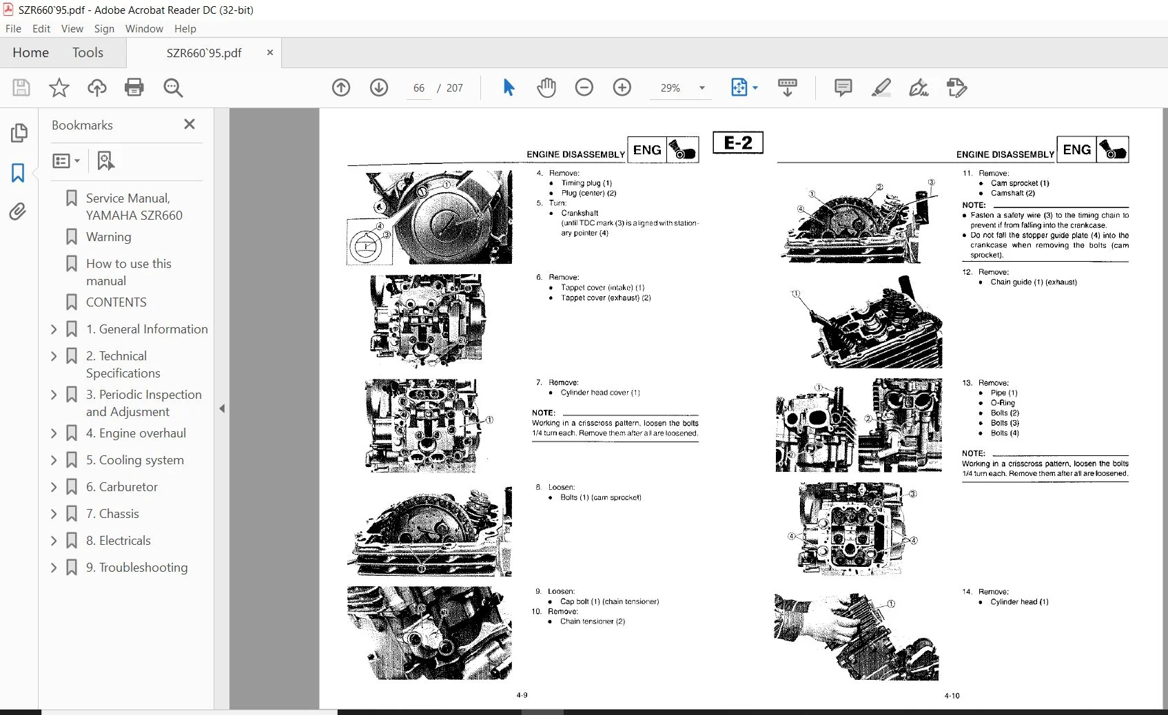
Engine Diassembly………………………………………… 65
Starter Motor and Hoses……………………………….. 65
Cylinder Head, Cylinder and Piston……………………… 65
Rotor and Starter Drivers……………………………… 67
Oil Filter and Water Pump……………………………… 68
Clutch and Balancer Gear………………………………. 69
Shift Lever and Oil Pump………………………………. 70
Crankcase (Right)…………………………………….. 71
Oil Strainer…………………………………………. 72
Balancer, Transmission and Shifter……………………… 72
Crankshaft…………………………………………… 73
Rocker Arm…………………………………………… 73
Valves………………………………………………. 74
Inspection and Repair…………………………………….. 75
Cylinder Head………………………………………… 75
Valves and Valve Guides……………………………….. 75
Valve Housing………………………………………… 76
Valve Spring…………………………………………. 78
Camshaft…………………………………………….. 78
Rocker Arms and Rocker Arm Shaft……………………….. 79
Camshaft Chain, Sprocket and Chain Guide………………… 79
Camshaft Chain Guide………………………………….. 80
Cylinder and Piston…………………………………… 80
Piston Rings…………………………………………. 81
Piston Pin…………………………………………… 82
Crankshaft…………………………………………… 82
Balancer Drive Gear and Balancer Gear…………………… 83
Electric Starter Drive………………………………… 83
Primary Drive………………………………………… 83
Clutch………………………………………………. 83
Transmission and Gearbox………………………………. 85
Oil Pump, Water Pump and Strainer………………………. 86
Oil Delivery Pipes……………………………………. 86
Crankcase……………………………………………. 86
Bearings and Oil Seals………………………………… 86
Circlip and Washer……………………………………. 86
Engine Assembly and Setting……………………………….. 87
Valves and Rocker Arms………………………………… 87
Valves………………………………………………. 87
Rocker Arms………………………………………….. 88
Crankshaft…………………………………………… 89
Balancer Shaft and Transmission………………………… 90
Shifter……………………………………………… 90
Balancer, Transmission and Shifter……………………… 91
Oil Strainer (exploded view)…………………………… 92
Crankcase (exploded view)……………………………… 92
Shift Lever and Oil Pump………………………………. 93
Crankcase (Assembling)………………………………… 93
Oil Strainer (Assembling)……………………………… 93
Shift Lever and Oil Pump………………………………. 94
Balancer Shaft Gear…………………………………… 95
Clutch………………………………………………. 95
Clutch and Balancer Gear………………………………. 96
Oil Filter and Water Pump……………………………… 98
Starter Gears………………………………………… 99
Cylinder……………………………………………..100
Cylinder Head…………………………………………101
Camshaft and Camshaft Chain…………………………….101
Cylinder Head, Cylinder and Piston………………………102
Pipes and Hoses……………………………………….105
Engine Reassembly…………………………………………106
5. Cooling system…………………………………………….108
Index……………………………………………………109
Cooling system……………………………………………110
Radiator…………………………………………………111
Job Instruction Chart………………………………….111
Inspection……………………………………………112
Assembly……………………………………………..112
Water Pump……………………………………………….113
Job Instruction Chart………………………………….113
Removal………………………………………………113
Inspection……………………………………………114
Assembly……………………………………………..114
Thermostat……………………………………………….114
Job Instruction Chart………………………………….114
Removal………………………………………………115
Inspection……………………………………………115
Assembly……………………………………………..115
6. Carburetor………………………………………………..116
Index……………………………………………………117
Carburetor……………………………………………….118
Technical Specifications/Tightening Torques/Exploded View….118
Section view………………………………………….118
Removal………………………………………………119
Diassembly……………………………………………120
Inspection……………………………………………121
Assembly……………………………………………..122
Installation………………………………………….125
Fuel Level Adjustment………………………………….125
Fuel Pump………………………………………………..126
Checking The Pump operation…………………………….126
Removal………………………………………………126
Inspection……………………………………………126
Installation………………………………………….126
7. Chassis…………………………………………………..127
Index……………………………………………………128
Front Wheel………………………………………………129
Removal………………………………………………129
Inspection……………………………………………130
Static Balancing………………………………………130
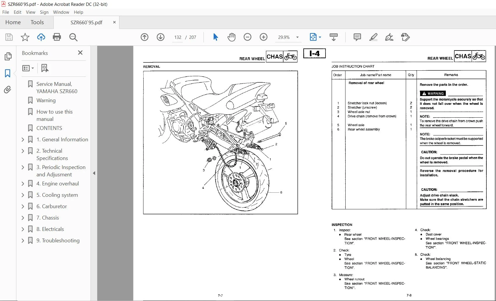
Rear Wheel……………………………………………….131
Removal………………………………………………132
Inspection……………………………………………132
Front and Rear Brake………………………………………133
Front Master Cylinder………………………………….133
Front Brake Caliper……………………………………133
Rear Master Cylinder…………………………………..134
Rear Brake Caliper…………………………………….134
Brake Pad Replacement………………………………….135
Front Brake Caliper Disassembly…………………………137
Rear Brake Caliper Disassembly………………………….138
Front Master Cylinder Disassembly……………………….139
Rear Master Cylinder Disassembly………………………..140
Inspection and Repair………………………………….141
Front Fork……………………………………………….143
Removal………………………………………………144
Oil Change……………………………………………145
Cleaning the Dust seal…………………………………147
Replacing the Seals and Bushes………………………….148
Adjustment……………………………………………154
Steering…………………………………………………155
Removal………………………………………………155
Inspection……………………………………………156
Installation………………………………………….156
Rear Shock Absorber……………………………………….158
Removal………………………………………………158
Note on Disposal………………………………………159
Inspection……………………………………………159
Adjustment……………………………………………159
Sving Arm………………………………………………..159
Removal………………………………………………160
Inspection……………………………………………161
Drive, Chain, Sprocket and Crown……………………………162
Removal………………………………………………162
Inspection……………………………………………163
8. Electricals……………………………………………….164
Index……………………………………………………165
Electrical Circuit Diagram…………………………………166
Colour Code…………………………………………..166
Electrical Components……………………………………..167
Switch Check……………………………………………..168
Switch Connection……………………………………..168
Main Switch Inspection…………………………………168
Light Inspection………………………………………….169
Blub Types……………………………………………169
Blub Inspection……………………………………….169
Ignition System…………………………………………..170
Circuit Diagram……………………………………….170
Diagnostics…………………………………………..171
Electrical Starting System…………………………………175
Circuit Diagram……………………………………….175
Starting Circuit Functioning……………………………176
Diagnostics…………………………………………..176
Starter Motor…………………………………………179
Charging System…………………………………………..182
Circuit Diagram……………………………………….182
Diagnostics…………………………………………..183
Light System……………………………………………..185
Circuit Diagram……………………………………….185
Diagnostics…………………………………………..186
Signalling System…………………………………………188
Circuit Diagram……………………………………….188
Diagnostics…………………………………………..189
Signalling System Control………………………………190
Cooling System……………………………………………195
Circuit Diagram……………………………………….195
Diagnostics…………………………………………..196
Electrical System Diagram………………………………….200
9. Troubleshooting……………………………………………201
Index……………………………………………………202
Failure to Start/Difficulties in Starting……………………203
Fuel System…………………………………………..203
Electrical System……………………………………..203
Poor Engine Compression………………………………..203
Poor Performance at Idle Speed……………………………..204
Unsatisfactory Performance at Medium-High Speed………………204
Difficulties in Changing Gear………………………………204
Gear Change Impossible…………………………………204
The Gear Pedal fail to move…………………………….204
Disengaging Gears……………………………………..204
Clutch Slides or Fails to Release…………………………..205
Clutch Slides…………………………………………205
Clutch Fails to Release………………………………..205
Overheating of Engine……………………………………..205
Excessive Engine Cooling…………………………………..205
Defective Brakes………………………………………….206
Poor Braking………………………………………….206
Oil Leaks or Malfunctioning of Front Fork……………………206
Oil Leaks…………………………………………….206
Malfunctioning………………………………………..206
Unstable Steering…………………………………………206
Defective Functioning of Lights and Indicators……………….207
Poor Headlight Illumination…………………………….207
Frequent Burning of Blub……………………………….207
The Direction Indicators Fail to Turn On…………………207
The Direction Indicators Fail to Turn Off………………..207
Delayed Turning on of Indicators………………………..207
Excessive Indicator Intermittence Frequency………………207
The Horn Fails to Work…………………………………207
Description:
1995 Yamaha SZR660 Service Manual
LAYOUT This: manual consists of chapters on the principal cycle components [see ‘Symbol Legend”).
(1}: This symbol, in the top rlght~hand corner of each page.
identifies the chapter graphically. (2): This title appears at the top of each page to the left ol the chapter symbol.
(8): The linai caption In the chapter ‘Perlodlc inspection and adjustment”. FORMAT Al the proceduressuggested in this maiuaiarearranged ina sequential. step by steporder. Theinlormation is written in such a way as to provide the mechanic with a handy. easy to read relerence containing explanations 0n al disassembly. repair. assembly and inspection operations.
Particularly Important procedure sequences (4) are shown belt-rem two rows cl asterisks (‘i and each procedure is preceded by the symbol ” s“. lMPORTANT SPECIFICATIONS – All data and special tools are contained in insets preceded by the specific symbol (5). e A number inscribed In round brackets indicates (6) the number at a pan.
whoreasa letterot the alphabet indicates alignment data or marks (7); turther indications are signaled by a letter ecbsed In an inset (8). e Theoonditionot a tautty component precedes anarrow lolowed by the procedure required andtlte symbol {9). ILLUSTRATED SEQUENCES The simplest disassemoly and reassembly sequences are shmm in an exploded drawing at the parts and a tabieinwhich the parts meritselvesaro numbered in progressiveorderotdlsassemblyfolloi-r the numbers progressively to periorm the disassembiy sequence.
Follow the numbered operations in the reverse order to perform the reassembly sequence. The table also includes notes to tacililate operations. EXPLODED DIAGRAMS In some chapters the disassembly section is preceded by exploded diagrams. These are designed to aid identification of components tor proper assembly, as well as the assembly procedures themselves.
Please Note:
- This is the SAME exact manual used by your dealers to fix your vehicle.
- The same can be yours in the next 2-3 mins as you will be directed to the download page immediately after paying for the manual.
- Any queries / doubts regarding your purchase, please feel free to contact [email protected]