Trusted Business
Verified & Licensed
Virus Free Files
100% Safe Downloads
Secure Payment
SSL Protected
Instant Delivery
Available Immediately
1996 NISSAN 300ZX Z32 Series Service Manual PDF DOWNLOAD
$35.95
1996 NISSAN 300ZX Z32 Series Service Manual PDF DOWNLOAD
Instant PDF Download
Available immediately
Save to Your Device
Download & keep forever
Antivirus Scanned
100% virus-free
Trusted Worldwide
175,000+ customers
Description
1996 NISSAN 300ZX Z32 Series Service Manual PDF DOWNLOAD
FILE DETAILS:
1996 NISSAN 300ZX Z32 Series Service Manual PDF DOWNLOAD
Language : English
Pages : 1526
Downloadable :Yes
File Type : PDF
IMAGES PREVIEW OF THE MANUAL:
TABLE OF CONTENTS:
1996 NISSAN 300ZX Z32 Series Service Manual PDF DOWNLOAD
fwd 1
Model Selection 0
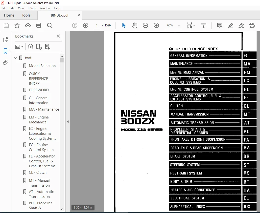
QUICK REFERENCE INDEX 1
FOREWORD 2
GI – General Information 0
MA – Maintenance 0
EM – Engine Mechanical 0
LC – Engine Lubrication & Cooling Systems 0
EC – Engine Control System 0
FE – Accelerator Control, Fuel & Exhaust Systems 0
CL – Clutch 0
MT – Manual Transmission 0
AT – Automatic Transmission 0
PD – Propeller Shaft & Differential Carrier 0
FA – Front Axle & Front Suspension 0
RA – Rear Axle & Rear Suspension 0
BR – Brake System 0
ST – Steering System 0
RS – Restraint System 0
BT – Body & Trim 0
HA – Heater & Air Conditioner 0
EL – Electrical System 0
IDX – Alphabetical Index 1
Foldout 0
Quick Reference Chart 3
at 4
QUICK REFERENCE INDEX 0
TABLE OF CONTENTS 4
PREPARATION AND PRECAUTIONS 6
Special Service Tools 6
Service Notice 7
Supplemental Restraint System (SRS) “AIR BAG” 8
DESCRIPTION 9
Cross-Sectional View 9
Hydraulic Control Circuits 10
Shift Mechanism 11
Control System 13
TROUBLE DIAGNOSES 16
How to Perform Trouble Diagnoses for Quick and Accurate Repair 16
Remarks 20
Diagnostic Trouble Code (DTC) Chart 21
Diagnosis by CONSULT 23
Preliminary Check 26
A/T Electrical Parts Location 37
Circuit Diagram for Quick Pinpoint Check 38
Wiring Diagram 39
Self-diagnosis 46
DTC P0720 VEHICLE SPEED SENSOR A/T (REVOLUTION SENSOR) CIRCUIT CHECK 52
VEHICLE SPEED SENSOR MTR CIRCUIT CHECK 54
DTC P1705 THROTTLE POSITION SENSOR CIRCUIT CHECK 56
DTC P0750 SHIFT SOLENOID VALVE A CIRCUIT CHECK 58
DTC P0755 SHIFT SOLENOID VALVE B CIRCUIT CHECK 60
DTC P1760 OVERRUN CLUTCH SOLENOID VALVE CIRCUIT CHECK 62
DTC P0740 TORQUE CONVERTER CLUTCH SOLENOID VALVE CIRCUIT CHECK 64
DTC P0710 FLUID TEMPERATURE SENSOR CUIRCUIT AND A/T CONTROL UNIT POWER SOURCE CIRCUIT CHECKS 66
DTC P0725 ENGINE SPEED SIGNAL CIRCUIT CHECK 69
DTC P0745 LINE PRESSURE SOLENOID VALVE CIRCUIT CHECK 71
DTC P0705 INHIBITOR, OVERDRIVE, KICKDOWN AND TROTTLE POSITION SWITCH CIRCUIT CHECK 73
DTC P0731 IMPROPER SHIFTING TO 1ST GEAR POSITION 77
DTC P0732 IMPROPER SHIFTING TO 2ND GEAR POSITION 79
DTC P0733 IMPROPER SHIFTING TO 3RD GEAR POSITION 81
DTC P0734 IMPROPER SHIFTING TO 4TH GEAR POSITION 83
Diagnostic Procedures for Symptoms 87
Diagnostic Procedure 1 87
Diagnostic Procedure 2 88
Diagnostic Procedure 3 88
Diagnostic Procedure 4 89
Diagnostic Procedure 5 90
Diagnostic Procedure 6 91
Diagnostic Procedure 7 92
Diagnostic Procedure 8 93
Diagnostic Procedure 9 94
Diagnostic Procedure 10 95
Diagnostic Procedure 11 96
Diagnostic Procedure 12 97
Diagnostic Procedure 13 98
Diagnostic Procedure 14 99
Diagnostic Procedure 15 100
Diagnostic Procedure 16 101
Diagnostic Procedure 17 101
Diagnostic Procedure 18 102
Diagnostic Procedure 19 102
Diagnostic Procedure 20 103
Electrical Components Inspection 103
Final Check 111
Symptom Chart 116
TROUBLE DIAGNOSES – A/T Shift Lock System 119
Description 119
Shift Lock Electrical Parts Location 119
Wiring Diagram 120
Diagnostic Procedure 121
Key Interlock Cable 124
Shift Lock Control Unit Inspection 125
Shift Lock Control Unit Inspection Table 126
Component Check 126
ON-VEHICLE SERVICE 127
Control Valve Assembly and Accumulators Inspection 127
Revolution Sensor Replacement 128
Rear Oil Seal Replacement 128
Parking Components Inspection 128
Inhibitor Switch Adjustment 129
Manual Control Linkage Adjustment 129
Kickdown Switch Adjustment 129
REMOVAL AND INSTALLATION 130
Removal 130
Installation 130
MAJOR OVERHAUL 132
RE4R01A 132
RE4R03A 134
Oil Channel – RE4R01A 136
Oil Channel – RE4R03A 137
Locations of Needle Bearings, Thrust Washers and Snap Rings – RE4R01A 138
Locations of Needle Bearings, Thrust Washers and Snap Rings – RE4R03A 139
DISASSEMBLY 140
Disassembly 140
REPAIR FOR COMPONENT PARTS 151
Oil Pump 151
Control Valve Assembly 155
Control Valve Upper Body 161
Control Valve Lower Body 166
Reverse Clutch 168
High Clutch 172
Forward and Overrun Clutch 174
Low & Reverse Brake 178
Forward Clutch Drum Assembly – RE4R01A 182
Forward Clutch Drum Assembly – RE4R03! 184
Rear Internal Gear and Forward Clutch Hub 186
Band Servo Piston Assembly 189
Parking Pawl Components 193
ASSEMBLY 195
Assembly (1) 195
Adjustment 200
Assembly (2) 204
SERVICE DATA AND SPECIFICATIONS (SDS) 214
General Specifications 214
Specifications and Adjustment – RE4R01A 214
Specifications and Adjustment – RE4R03A 218
br 222
QUICK REFERENCE INDEX 0
TABLE OF CONTENTS 222
PRECAUTIONS AND PREPARATION 224
Precautions 224
Commercial Service Tools 224
CHECK AND ADJUSTMENT 225
Checking Brake Fluid Level 225
Checking Brake Line 225
Changing Brake Fluid 225
Bleeding Procedure 226
BRAKE HYDRAULIC LINE 227
Removal 227
Inspection 227
Installation 228
CONTROL VALVE 229
Proportioning Valve 229
BRAKE PEDAL AND BRACKET 230
Removal and Installation 230
Inspection 230
Adjustment 230
MASTER CYLINDER 232
Removal 232
Disassembly 232
Inspection 233
Assembly 233
Installation 233
BRAKE BOOSTER 234
On-vehicle Service 234
Removal 234
Inspection 234
VACUUM HOSE 235
Removal and Installation 235
Inspection 235
FRONT DISC BRAKE (OPF25VA) 236
Pad Replacement 236
Removal and Installation 237
Disassembly 237
Inspection 237
Assembly 238
Inspection (On-vehicle) 239
REAR DISC BRAKE (OPZ11V) 240
Pad Replacement 240
Removal and Installation 241
Disassembly 241
Inspection 242
Assembly 243
Inspection (On-vehicle) 243
PARKING BRAKE CONTROL 244
Removal and Installation 244
Inspection 244
Adjustment 244
PARKING DRUM BRAKE (DS17HD) 245
Shoe Replacement 245
Shoe Clearance Adjustment 246
Breaking in Parking Brake Shoes 246
Drum Inspection 246
ANTI-LOCK BRAKE SYSTEM 247
Purpose 247
Operation 247
System Components 247
Hydraulic Circuit 248
Removal and Installation 249
TROUBLE DIAGNOSES 250
Wiring Diagram – ABS – 250
Component Parts and Harness Connector Location 259
SERVICE DATA AND SPECIFICATIONS (SDS) 277
General Specifications 277
Inspection and Adjustment 277
bt 278
QUICK REFERENCE INDEX 0
TABLE OF CONTENTS 278
PRECAUTIONS 279
Service Notice 279
Supplemental Restraint System (SRS) “AIR BAG” 279
GENERAL SERVICING 280
Clip and Fastener 280
BODY END 282
Body Front End 282
Body Rear End and Opener 284
DOOR 287
INSTRUMENT PANEL 288
INTERIOR TRIM 290
Side, Luggage and Floor Trim 290
Trunk Room Trim – Convertible model 293
Door Trim 294
Back Door Trim – Standard model 295
Roof Trim – T-bar roof model 296
EXTERIOR 297
T-BAR ROOF 306
CONVERTIBLE ROOF 308
Storage Lid 308
Top Cover and Headliner 309
Linkage 310
Adjustment 312
SEAT 313
WINDSHIELD AND WINDOWS 315
Windshield 315
Side Window 316
Back Door Window 317
REAR AIR SPOILER AND MIRROR 318
Rear Air Spoiler 318
Door Mirror 318
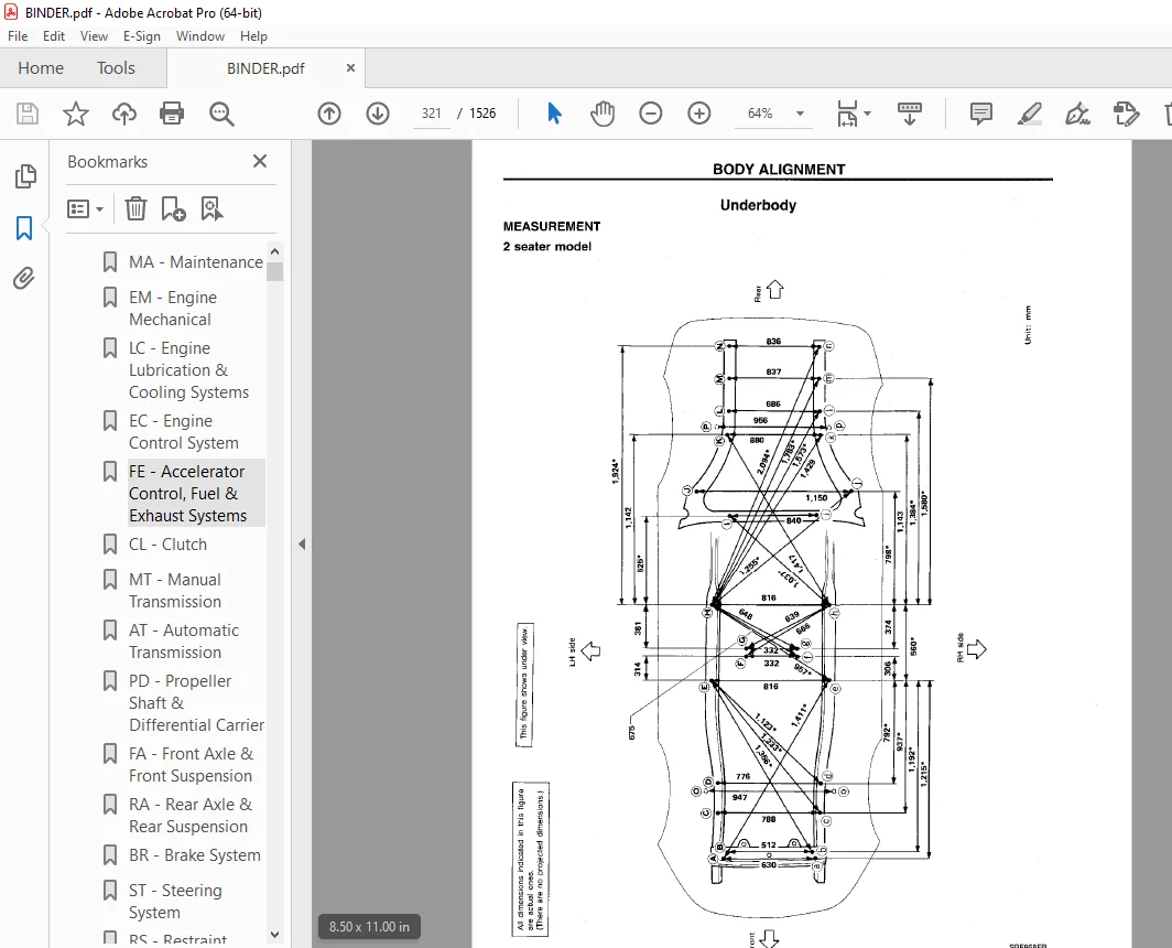
BODY ALIGNMENT 319
Engine Compartment 319
Underbody 321
cl 325
QUICK REFERENCE INDEX 0
TABLE OF CONTENTS 325
PRECAUTIONS AND PREPARATION 326
Precautions 326
Special Service Tools 326
Commercial Service Tools 326
CLUTCH SYSTEM 327
INSPECTION AND ADJUSTMENT 329
Adjusting Clutch Pedal 329
Bleeding Procedure 330
HYDRAULIC CLUTCH CONTROL 331
Clutch Master Cylinder 331
Operating Cylinder 332
Clutch Booster 333
CLUTCH RELEASE MECHANISM 335
CLUTCH DISC AND CLUTCH COVER 337
Clutch Disc 337
Clutch Cover and Flywheel 338
SERVICE DATA AND SPECIFICATIONS (SDS) 339
General Specifications 339
Inspection and Adjustment 339
ec 340
QUICK REFERENCE INDEX 0
TABLE OF CONTENTS 340
PRECAUTIONS AND PREPARATION 342
Supplemental Restraint System (SRS) “AIR BAG” 342
Precautions for On Board Diagnostic (OBD) System of Engine and A/T 342
Engine Fuel & Emission Control System 343
Special Service Tools 344
Precautions 345
ENGINE AND EMISSION CONTROL OVERALL SYSTEM 347
Circuit Diagram 347
System Diagram 349
ECCS Component Parts Location 351
Vacuum Hose Drawing 354
System Chart 356
ENGINE AND EMISSION BASIC CONTROL SYSTEM DESCRIPTION 357
Multiport Fuel Injection (MFI) System 357
Electronic Ignition (EI) System 360
Air Conditioning Cut Control 361
Fuel Cut Control (at no load & high engine speed) 361
EVAPORATIVE EMISSION SYSTEM 362
Description 362
Inspection 362
POSITIVE CRANKCASE VENTILATION 364
Description 364
Inspection 364
BASIC SERVICE PROCEDURE 365
Fuel Pressure Release 365
Fuel Pressure Check 365
Injector Removal and Installation 366
Direct Ignition System – How to Check Idle Speed and Ignition Timing 367
Idle Speed/Ignition Timing/Idle Mixture Ratio Adjustment 369
ON BOARD DIAGNOSTIC SYSTEM DESCRIPTION 376
Introduction 376
Two Trip Detection Logic 376
Diagnostic Troubl eCode (DTC) 376
Freeze Frame Data 378
Malfunction Indicator Lamp (MIL) 378
OBD System Operation Chart 383
CONSULT 388
Generic Scan Tool (GST) 400
TROUBLE DIAGNOSIS – Introduction 402
Introduction 402
Diagnostic Worksheet 403
TROUBLE DIAGNOSIS – Work Flow 404
Work Flow 404
Description for Work Flow 405
TROUBLE DIAGNOSIS – Basic Inspection 406
Basic Inspection 406
TROUBLE IDAGNOSIS – General Description 409
Diagnostic Trouble Code (DTC) Chart 409
Fail-Safe Chart 424
Symptom Matrix Chart 426
CONSULT Reference Value in Data Monitor Mode 429
Major Sensor Reference Graph in Data Monitor Mode 432
ECM Terminals and Reference Value 434
TROUBLE DIAGNOSIS FOR POWER SUPPLY 442
Main Power Supply and Ground Circuit 442
DTC P0100, Mass Air Flow Sensor (MAFS) (DTC: 0102) 447
DTC P0110, Intake Air Temperature Sensor (DTC: 0401) 452
DTC P0115, Engine Coolant Temperature Sensor (ECTS) (DTC: 0113) 457
DTC P0120, Throttle Position Sensor (DTC: 0403) 461
DTC P0125, Engine Coolant Temperature (ECT) Sensor (DTC: 0908) 466
DTC P0130, P0150, Closed Loop Control (DTC: 0307, 0308) 471
DTC P0130, Front Heated Oxygen Sensor (Front HO2S) (Right bank) (DTC: 0503) 472
DTC P0135, Front Heated Oxygen Sensor Heater (Right bank) (DTC: 0901) 477
DTC P0136, Rear Heated Oxygen Sensor (Rear HO2S) (Right bank) (DTC: 0707) 480
DTC P0141, Rear Heated Oxygen Sensor Heater (Right bank) (DTC: 0902) 485
DTC P0150, Front Heated Oxygen Sensor (Front HO2S) (Left bank) (DTC: 0303) 489
DTC P0155, Front Heated Oxygen Sensor Heater (Left bank) (DTC: 1001) 494
DTC P0156, Rear Heated Oxygen Sensor (Rear HO2S) (Left bank) (DTC: 0708) 497
DTC P0161, Rear Heated Oxygen Sensor Heater (Left bank) (DTC: 1002) 502
DTC P0171, Fuel Injection System Function (Right bank) (Lean side) (DTC: 0115) 506
DTC P0172, Fuel Injection System Function (Right bank) (RIch side) (DTC: 0114) 512
DTC P0174, Fuel Injection System Function (Left bank) (Lean side) (DTC: 0210) 518
DTC P0175, Fuel Injection System Function (Left bank) (Rich side ) (DTC: 0209) 524
DTC P0180, Fuel Temperature Sensor (DTC: 0402) 530
DTC P0300 – P0306, Multiple Cylinder Misfire, No 1 – 6 Cylinder Misfire (DTC: 0701 – 0603) 533
DTC P0325, Knock Sensor (KS) (DTC: 0304) 538
DTC P0335, Crankshaft Position Sensor (CKPS) (OBD) (DTC: 0802) 541
DTC P0340, Camshaft Position Sensor (CMPS) (DT 545
DTC P0400, EGR Function (DTC: 0302) 551
DTC P0420, P0430, Three Way Catalyst Function (DTC: 0702, 0703) 559
DTC P0443, Evaporative Emission (EVAP) Canister Purge Control Solenoid Valve (DTC: 0807) 562
DTC P0500, Vehicle Speed Sensor (VSS) (DTC: 0104) 572
DTC P0505, Idle Air Control Valve (IACV) – Auxiliary Air Control (AAC) Valve (DTC: 0205) 576
DTC P0600, A/T Control (DTC: P0600) 580
DTC P0605, Engine Control Module (ECM)-ECCS Control Module (DTC: 0301) 583
DTC P0705, Park/Neutral Position Switch (DTC: 1003) 585
DTC P1150, P1155, Wastegate Valve Control Solenoid Valve (DTC: 1306, 1307) 589
DTC P1160, Turbocharger Boost Sensor (DTC: 0206) 593
DTC P1220, Fuel Pump Control Module (FPCM) (DTC: 1305) 599
DTC P1320, Ignition Signal (DTC: 0201) 605
DTC P1336, Crankshaft Position Sensor (CKPS) (OBD) (COG) (DTC: 0905) 614
DTC P1400, EGRC-Solenoid Valve (DTC: 1005) 618
DTC P1401, EGR Temperature Sensor (DTC: 0305) 622
DTC P1443, Canister Control Vacuum Check Switch (DTC: 0113) 627
DTC P1605, A/T Diagnosis Communication Line (DTC: 0804) 632
DTC P1900, Cooling Fan (DTC: 1308) 635
TROUBLE DIAGNOSIS FOR NON-DETECTABLE ITEMS 650
Injector 650
Start Signal 653
Fuel Pump Control 655
IACV-Air Regulator 661
Fuel Pressure Regulator Control 664
Power Steering Oil Pressure Switch 669
IACV-FICD Solenoid Valve 672
MIL & Data Link Connector 676
TROUBLE DIAGNOSIS – Index 677
Alphabetical & P No Index for DTC 677
SERVICE DATA AND SPECIFICATIONS (SDS) 679
General Specifications 679
Inspection and Adjustment 679
el 681
QUICK REFERENCE INDEX 0
TABLE OF CONTENTS 681
PRECAUTIONS 684
Supplemental Restraint System (SRS) “AIR BAG” 684
Special Service Tools 684
HARNESS CONNECTOR 685
Description 685
STANDARDIZED RELAY 686
Description 686
POWER SUPPLY ROUTING 690
Schematic 690
Wiring Diagram – POWER – 692
Fuse 701
Fusible Link 701
Circuit Breaker Inspection 701
GROUND DISTRIBUTION 702
BATTERY 706
How to Handle Battery 706
Service Data and Specifications (SDS) 708
STARTING SYSTEM 709
System Description 709
Wiring Diagram – START – 710
Construction 712
Removal and Installation 712
Service Data and Specifications (SDS) 713
CHARGING SYSTEM 714
System Description 714
Wiring Diagram – CHARGE – 715
Construction 716
Removal and Installation 717
Service Data and Specifications 718
COMBINATION SWITCH 719
Combination Switch/Check 719
Combination Switch/Replacement 720
INSTRUMENT SWITCH 722
Check 722
HEADLAMP 724
System Description (For U S A ) 724
Schematic 726
Wiring Diagram – H/LAMP – 727
Trouble Diagnoses 730
HEADLAMP – Daytime Light System 731
System Description (For Canada) 732
Operation (Daytime light system equipped model) 733
Schematic 733
Wiring Diagram – DTRL – 733
Trouble Diagnoses (Daytime Light) 738
Aiming Adjustment 740
Bulb Replacement 741
EXTERIOR LAMP 742
Clearance, License and Tail Lamps/Schematic 742
Clearance, License, Tail and Stop Lamps/Wiring Diagram – TAIL – 743
Stop and Tail Lamp Sensor Check 746
Back-up Lamp/Wiring Diagram – BACK/L – 747
Front Fog lamp/System Description 748
Front Fog Lamp/Schematic 749
Front Fog Lamp/Wiring Diagram – F/FOG – 750
Turn Signal and Hazard Warning Lamps/System Description 753
Turn Signal and Hazard Warning Lamps/Schematic 755
Turn Signal and Hazard Warning Lamps/Wiring Diagram – TURN – 756
Turn Signal and Hazard Warning lamps/Trouble Diagnoses 759
Combination Flasher Unit Check 759
Bulb Specifications 760
INTERIOR LAMP 761
Illumination/System Description 761
Illumination/Schematic 762
Illumination/Wiring Diagram – ILL – 763
Interior, Spot, Foot, Luggage Room and Trunk Room Lamps/System Description 766
Bulb Specifications 767
Interior, Spot, Foot, Luggage Room and Trunk Room Lamps/Wiring Diagram – INT/L – 768
METER AND GAUGES 772
System Description 772
Combination Meter 773
Speedometer, Tachometer, Temp , Oil, Fuel and Boost Gauges/Wiring Diagram – METER – 774
Inspection/Fuel Gauge and Water Temperature Gauge 776
Fuel Tank Gauge Unit Check 777
Thermal Transmitter Check 777
Oil Pressure Sending Unit Check 777
Boost Sensor Check 778
Vehicle Speed Sensor Signal Check 778
WARNING LAMPS AND CHIME 779
Warning Lamps/Schematic 779
Warning Lamps/Wiring Diagram – WARN – 780
Warning Chime/System Description 786
Warning Chime/Wiring Diagram – CHIME – 788
Fuel Warning Lamp Sensor Check 790
Diode Check 790
Warning Chime Check 790
TIME CONTROL SYSTEM 791
System Description 791
Schematic 793
Wiring Diagram – TIME – 794
Trouble Diagnoses 801
WIPER AND WASHER 811
Front Wiper and Washer/System Description 811
Front Wiper and Washer/Schematic 813
Front Wiper and Washer/Wiring Diagram – WIPER – 814
Rear Wiper and Washer/System Description 817
Rear Wiper and Washer/Wriing Dagram – WIP/R – 818
Headlamp Washer/Wiring Diagram – HLC – 819
Installation 821
Washer Nozzle Adjustment 822
Check Valve 822
Wiper Amplifier Check 822
POWER WINDOW 823
System Description 823
Schematic 825
Wiring Diagram – WINDOW – 826
Power Window Amp Inspection 829
POWER DOOR LOCK 830
System Description 830
Schematic 831
Wiring Diagram – D/LOCK – 832
Door Lock Timer Inspection 836
Electrical Components Inspection 837
POWER DOOR MIRROR 838
Wiring Diagram – MIRROR – 838
FUEL FILLER LID OPENER 840
Wiring Diagram – F/LID – 840
TRUNK LID OPENER 841
Wiring Diagram – T/LID – 841
CONVERTIBLE ROOF 843
Storage Lid Opener/System Description 843
Storage Lid Opener/Schematic 844
Storage Lid Opener/Wiring Diagram – ST/LID – 845
Convertible Roof Opener/Wiring Diagram – C/ROOF – 849
HORN, CIGARETTE LIGHTER AND CLOCK 850
Wiring Diagram – HORN – 850
REAR WINDOW DEFOGGER AND DOOR MIRROR DEFOGGER 852
Wiring Diagram – DEF – 852
Filament Check 855
Filament Repair 856
AUDIO AND POWER ANTENNA 857
Audio/System Description 857
Audio/Wiring Diagram – AUDIO – 858
Schematic 862
Power Antenna/System Description 863
Power Antenna/Wiring Diagram – P/ANT – 864
Trouble Diagnoses 865
Location of Antenna 867
Antenna Rod Replacement 867
Radio Fuse Check 868
Window Antenna Repair 869
POWER SEAT 870
Schematic 870
Wiring Diagram – SEAT – 871
MULTI-REMOTE CONTROL SYSTEM 874
System Description 874
Schematic 877
Wiring Diagram – MULTI – 878
Trouble Diagnoses Preliminary Inspection 884
Trouble Diagnoses 885
AUTOMATIC SPEED CONTROL DEVICE (ASCD) 891
Component Parts and Harness Connector Location 891
System Description 892
Schematic 894
Wiring Diagram – ASCD – 895
Trouble Diagnoses 901
THEFT WARNING SYSTEM 920
Component Parts and Harness Connector Location 920
Trouble Diagnoses 921
Schematic 922
Wiring Diagram – THEFT – 924
Trouble Diagnoses 933
LOCATION OF ELECTRICAL UNITS 950
Engine Compartment 950
Passenger Compartment 951
Luggage Compartment 952
HARNESS LAYOUT 954
Outline 954
Engine Room Harness 955
Main Harness 958
Air Bag Harness 961
Engine Control Harness 962
Body Harness 964
Door Harness LH 970
Door Harness RH 970
Back Door Harness 971
Alternator Harness 971
FUSE BLOCK JUNCTION BOX (J/B) 0
Terminal Arrangement 0
ELECTRICAL UNIT 1
Terminal Arrangement 1
em 972
QUICK REFERENCE INDEX 0
TABLE OF CONTENTS 972
PRECAUTIONS 973
Supplemental Restraint System (SRS) “AIR BAG” 973
Parts Requiring Angular Tightening 973
Liquid Gasket Application Procedure 973
PREPARATION 974
Special Service Tools 974
Commercial Service Tools 976
OUTER COMPONENT PARTS 977
COMPRESSION PRESSURE 980
Measurement of Compression Pressure 980
OIL PAN 981
Removal 981
Installation 982
TIMING BELT 983
Removal 984
Inspection 985
Installation 986
OIL SEAL REPLACEMENT 990
THROTTLE BODIES 992
Precaution 992
Installation 992
CYLINDER HEAD 994
Removal 995
Disassembly 996
Inspection 997
Assembly 1002
Installation 1003
TURBOCHARGERS 1006
Removal 1006
Inspection 1008
CHARGE AIR COOLERS 1011
Removal 1011
ENGINE REMOVAL 1012
M/T Model 1013
A/T Model 1015
CYLINDER BLOCK 1016
Disassembly 1017
Inspection 1017
Assembly 1024
SERVICE DATA AND SPECIFICATIONS (SDS) 1027
General Specifications 1027
Inspection and Adjustment 1028
fa 1035
QUICK REFERENCE INDEX 0
TABLE OF CONTENTS 1035
PRECAUTIONS AND PREPARATION 1036
Precautions 1036
Special Service Tools 1036
Commercial Service Tools 1036
FRONT AXLE AND FRONT SUSPENSION 1038
ON-VEHICLE SERVICE 1039
Front Axle and Front Suspension Parts 1039
Front Wheel Bearing 1041
Front Wheel Alignment 1042
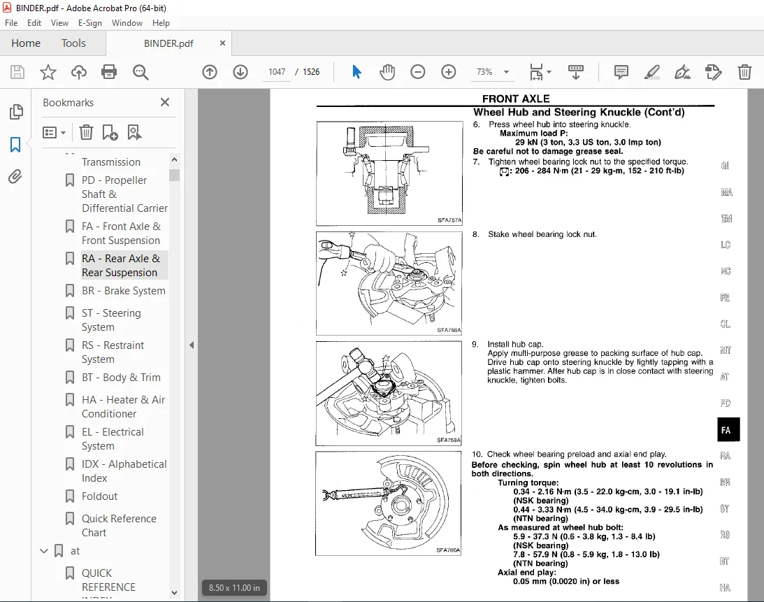
FRONT AXLE 1044
Wheel Hub and Steering Knuckle 1044
FRONT SUSPENSION 1048
Coil Spring and Shock Absorber 1049
Third Link and Upper Link 1050
Transverse Link and Lower Ball Joint 1052
Tension Rod and Stabilizer Bar 1053
ADJUSTABLE SHOCK ABSORBER 1054
Trouble Diagnoses 1055
SERVICE DATA AND SPECIFICATIONS (SDS) 1062
General Specifications 1062
Inspection and Adjustment 1063
fe 1064
QUICK REFERENCE INDEX 0
TABLE OF CONTENTS 1064
ACCELERATOR CONTROL SYSTEM 1065
Adjusting Accelerator Wire 1065
FUEL SYSTEM 1066
EXHAUST SYSTEM 1068
foldout 1070
QUICK REFERENCE INDEX 0
ELECTRICAL SYSTEM 2
FUSE BLOCK JUNCTION BOX (J/B) 1070
Terminal Arrangement 1070
ELECTRICAL UNIT 1071
Terminal Arrangement 1071
gi 1072
QUICK REFERENCE INDEX 0
TABLE OF CONTENTS 1072
PRECAUTIONS 1073
Precautions for Suplemental Restraint System (SRS) “AIR BAG” 1073
General Precautions 1073
Precautions for Multiport Fuel Injection System or ECCS Engine 1075
Precautions for Three Way Catalyst 1075
Precautions for Turbocharger 1075
Engine Oils 1076
Precautions for Fuel 1077
Precautions for Air Conditioning 1077
HOW TO USE THIS MANUAL 1078
HOW TO READ WIRING DIAGRAMS 1080
Sample/Wiring Diagram – EXAMPL – 1080
Description 1082
Wiring Diagram Codes (Cell Codes) 1088
HOW TO PERFORM EFFICIEINT DIAGNOSIS FOR AN ELECTRICAL INCIDENT 1090
Work Flow 1090
Incident Simulation Test 1091
Circuit Inspection 1095
HOW TO FOLLOW FLOW CHART IN TROUBLE DIAGNOSES 1101
CONSULT CHECKING SYSTEM 1104
Function and System Application 1104
Lithium Battery Replacement 1104
Checking Equipment 1104
IDENTIFICATION INFORMATION 1105
Model Variation 1105
Identification Number 1107
Dimensions 1109
Wheels and Tires 1109
LIFTING POINTS AND TOW TRUCK TOWING 1110
Preparation 1110
Board-on Lift 1110
Garage Jack and Safety Stand 1111
2-pole Lift 1112
Tow Truck Towing 1112
TIGHTENING TORQUE OF STANDARD BOLTS 1114
SAE J1930 TERMINOLOGY LIST 1115
SAE J1930 Terminology List 1115
ha 1119
QUICK REFERENCE INDEX 0
TABLE OF CONTENTS 1119
MANUAL AND AUTO 1120
PRECAUTIONS AND PREPARATION 1120
Supplemental Restraint System (SRS) “AIR BAG” 1120
Introduction 1120
Identificiation 1120
Precautions for Working with HFC-134a (R-134a) 1122
General Refrigerant Precautions 1122
Precautions for Refrigerant Connection 1123
Precautions for Servicing Compressor 1124
Special Service Tools 1124
HFC-134a (R-134a)) Service Tools and Equipment 1125
Precautions for Service Equipment 1127
DESCRIPTION 1129
Refrigeration Cycle 1129
Component Layout 1130
Discharge Air Flow 1131
Acceleration Cut System 1132
Water Cock Control System 1132
MANUAL 1133
DESCRIPTION 1133
Control Operation 1133
TROUBLE DIAGNOSES 1134
Contents 1134
Wiring Diagram – A/C, M – 1155
SYSTEM DESCRIPTION 1182
Control Switches 1182
Specifications 1182
AUTO 1184
DESCRIPTION 1184
Features 1184
Control Operation 1185
TROUBLE DIAGNOSES 1186
Contents 1186
Wiring Diagram – A/C, A – 1213
SYSTEM DESCRIPTION 1247
Specifications 1247
System Operation 1250
MANUAL AND AUTO 1254
SERVICE PROCEDURES 1254
HFC-134a (R-134a) Service Procedure 1254
Maintenance of Lubricant Quantity in Compressor 1256
Refrigerant Lines 1258
Checking Refrigerant Leaks 1260
Compressor Mounting 1262
Belt Tension 1262
Fast Idle Control Device (FICD) 1262
Removal and Installation – Compressor 1263
Compressor – Model DKS-16H (ZEXEL make) 1264
SERVICE DATA AND SPECIFICATIONS (SDS) 1266
General Specifications 1266
Inspection and Adjustment 1266
idx 1267
QUICK REFERENCE INDEX 0
lc 1275
QUICK REFERENCE INDEX 0
TABLE OF CONTENTS 1275
PRECAUTIONS 1276
Supplemental Restraint System (SRS) “AIR BAG” 1276
Liquid Gasket Application Procedure 1276
PREPARATION 1277
Special Service Tools 1277
ENGINE LUBRICATION SYSTEM 1278
Lubrication Circuit 1278
Oil Pressure Check 1279
Oil Filter Bracket (Turbocharger model) 1279
Oil Pump 1279
Oil Cooler (Turbocharger model) 1281
ENGINE COOLING SYSTEM 1282
Cooling Circuit 1282
System Check 1282
Water Pump 1283
Thermostat 1284
Cooling Fan (Crankshaft driven) 1285
Cooling Fan (Motor driven) 1285
Radiator 1286
Overheating Cause Analysis 1291
SERVICE DATA AND SPECIFICATIONS (SDS) 1292
Engine Lubrication System 1292
Engine Cooling System 1292
ma 1293
QUICK REFERENCE INDEX 0
TABLE OF CONTENTS 1293
PRECAUTIONS 1294
Supplemental Restraint System (SRS) “AIR BAG” 1294
GENERAL MAINTENANCE 1295
PERIODIC MAINTENANCE 1297
Schedule 1 1298
Schedule 2 1299
RECOMMENDED FLUIDS AND LUBRICANTS 1300
Fluids and Lubricants 1300
SAE Viscosity Number 1300
Anti-freeze Coolant Mixture Ratio 1301
ENGINE MAINTENANCE 1302
Checking Drive Belts 1302
Changing Engine Coolant 1303
Checking Fuel Lines 1304
Changing Fuel Filter 1305
Changing Air Cleaner Filter 1305
Changing Engine Oil 1305
Changing Oil Filter 1306
Changing Spark Plugs 1307
Checking EVAP Vapor Purge Lines 1308
CHASSIS AND BODY MAINTENANCE 1309
Checking Exhaust System 1309
Checking Clutch Fluid Level and Leaks 1309
Checking M/T Oil 1309
Changing M/T Oil 1309
Checking A/T Fluid 1309
Changing A/T Fluid 1310
Checking Differential Gear Oil 1311
Changing Differential Gear Oil 1311
Balancing Wheels 1311
Tire Rotation (Non-Turbocharger model only) 1311
Checking Brake Fluid Level and Leaks 1312
Checking Disc Brake 1312
Checking Steering Gear and Linkage 1312
Checking Power Steering Fluid and Lines 1313
Checking SUPER HICAS Linkage (With SUPER HICAS system) 1313
Lubricating Locks, Hinges and Hood Latches 1314
Checking Seat Belts, Buckles, Retractors, Anchors and Adjusters 1314
SERVICE DATA AND SPECIFICATIONS (SDS) 1315
Engine Maintenance 1315
Chassis and Body Maintenance 1315
mt 1316
QUICK REFERENCE INDEX 0
TABLE OF CONTENTS 1316
PREPARATION 1317
Special Service Tools 1317
Commercial Service Tool 1318
ON-VEHICLE SERVICE 1319
Replacing Rear Oil Seal 1319
Position Switch Check 1319
REMOVAL AND INSTALLATION 1320
Removal 1320
Installation 1320
MAJOR OVERHAUL 1321
Case Components 1321
Gear Components 1322
Shift Control Components 1324
DISASSEMBLY 1326
Case Components 1326
Shift Control Components 1327
Gear Components 1328
INSPECTION 1332
Shift Control Components 1332
Gear Components 1332
ASSEMBLY 1334
Gear Components 1334
Shift Control Components 1342
Case Components 1342
SERVICE DATA AND SPECIFICATIONS (SDS) 1345
General Specifications 1345
Inspection and Adjustment 1345
pd 1347
QUICK REFERENCE INDEX 0
TABLE OF CONTENTS 1347
PREPARATION 1348
Special Service Tools 1348
Commercial Service Tools 1351
PROPELLER SHAFT 1352
On-vehicle Service 1353
Removal 1353
Installation 1354
Inspection 1354
Disassembly 1355
Assembly 1355
FINAL DRIVE 1356
ON-VEHICLE SERVICE/REMOVAL AND INSTALLATION 1356
Front Oil Seal Replacement (R200V) 1356
Side Oil Seal Replacement 1356
Removal 1357
Installation 1357
FINAL DRIVE 1358
Model R200V 1358
Model R230V 1359
DISASSEMBLY 1360
Pre-inspection 1360
Differential Carrier 1360
Differential Case 1362
INSPECTION 1363
Ring Gear and Drive Pinion 1363
Bearing 1363
Differential Case Assembly 1363
ADJUSTMENT (R200V) 1364
Side Bearing Preload 1364
Pinion Gear Height and Pinion Bearing Preload 1365
ADJUSTMENT (R230V) 1370
Side Bearing Preload 1370
Pinion Gear Height 1371
ADJUSTMENT 1374
Tooth Contact 1374
ASSEMBLY 1375
Differential Case 1375
Differential Carrier 1376
SERVICE DATA AND SPECIFICATIONS (SDS) 1381
Propeller Shaft 1381
Final Drive 1381
ra 1384
QUICK REFERENCE INDEX 0
TABLE OF CONTENTS 1384
PRECAUTIONS AND PREPARATION 1385
Precautions 1385
Special Service Tools 1385
Commercial Service Tools 1386
REAR AXLE AND REAR SUSPENSION 1387
ON-VEHICLE SERVICE 1388
Rear Axle and Rear Suspension Parts 1388
Rear Wheel Bearing 1388
Rear Wheel Alignment 1388
Drive Shaft 1390
REAR AXLE AND REAR SUSPENSION ASSEMBLY 1391
Removal and Installation 1391
REAR AXLE 1392
Wheel Hub and Axle Housing 1392
Drive Shaft 1395
REAR SUSPENSION 1399
Coil Spring and Shock Absorber 1400
Multi-link and Lower Ball Joint 1401
Stabilizer Bar 1402
ADJUSTABLE SHOCK ABSORBER 1403
Removal and Installation 1403
Inspection 1403
Trouble Diagnosis 1403
SUPER HICAS 1404
Rear Wheel Alignment 1404
Rear Axle Housing Ball Joint 1405
SERVICE DATA AND SPECIFICATIONS (SDS) 1406
General Specifications 1406
Inspection and Adjustment 1407
rs 1408
QUICK REFERENC INDEX 0
TABLE OF CONTENTS 1408
PRECAUTION 1409
Supplemental Restraint System (SRS) “AIR BAG” 1409
SEAT BELTS 1410
Front Seat Belt 1410
Rear Seat Belt (2+ 2 model) 1411
SUPPLEMENTAL RESTRAINT SYSTEM (SRS) 1412
Precautions for SRS “Air Bag” Service 1412
Special Service Tools 1412
Description 1413
SRS Component Parts Location 1414
Maintenance Items 1415
Removal and Installation – Diagnosis Unit and Sensors 1416
Removal – Air Bag Module and Spiral Cable 1417
Removal – Front Passenger Air Bag Module 1418
Installation – Air Bag Module and Spiral Cable 1419
Installation – Front Passenger Air Bag Module 1420
Disposal or Air Bag Module 1421
TROUBLE DIAGNOSES – Supplemental Restraint System (SRs) 1425
Schematic 1425
Wiring Diagram 1426
Self-diagnosis 1430
Diagnostic Procedure 1 1436
Diagnostic Procedure 2 1437
Collision Diagnosis 1438
st 1439
QUICK REFERENCE INDEX 0
TABLE OF CONTENTS 1439
PRECAUTIONS AND PREPARATION 1440
Supplemental Restraint System (SRS) “AIR BAG” 1440
Steering System 1440
Special Service Tools 1440
Commercial Service Tools 1442
CONSULT Program Card 1442
ON-VEHICLE SERVICE 1443
Checking Steering Wheel Play 1443
Checking Neutral Position on Steering Wheel 1443
Front Wheel Turning Angle 1443
Adjusting Rack Retainer 1444
Checking and Adjusting Drive Belts (For power steering) 1444
Checking Fluid Level 1444
Checking Fluid Leakage 1445
Bleeding Hydraulic System 1445
Checking Steering Wheel Turning Force (For power steering) 1445
Checking Hydraulic System 1446
STEERING WHEEL AND STEERING COLUMN 1447
Removal and Installation 1447
Disassembly and Assembly 1449
Inspection 1450
POWER STEERING GEAR AND LINKAGE (Model PR26AE) 1451
Removal and Installation 1451
Disassembly 1454
Inspection 1454
Assembly 1455
Adjustment 1460
POWER STEERING OIL PUMP 1462
Pre-disassembly Inspection 1462
Disassembly 1462
Inspection 1463
Assembly 1463
TWIN ORIFICE POWER STEERING SYSTEM 1465
Hydraulic Circuit 1465
Schematic 1465
Wiring Diagram 1466
Trouble Diagnoses 1469
SUPER HICAS SYSTEM 1478
HICAS Component Parts Location 1478
System Diagram 1478
On-vehicle Service 1479
Repair of Component Parts 1481
Trouble Diagnoses 1486
SERVICE DATA AND SPECIFICATIONS 1525
General Specifications 1525
Inspection and Adjustment 1525
Customer Support: [email protected]
https://vimeo.com/849852845?share=copy
DESCRIPTION:
1996 NISSAN 300ZX Z32 Series Service Manual PDF DOWNLOAD
FOREWORD
- This manual contains maintenance and repair procedures for the 1996 Nissan 300ZX. In order to assure your safety and the efficient functioning of the vehicle, this manual should be read thoroughly.
- It is especially important that the PRECAUTIONS in the GI section be completely understood before starting any repair task.
- All information in this manual is based on the latest product information at the time of publication. The right is reserved to make changes in specifications and methods at any time without notice.
IMPORTANT SAFETY NOTICE
- The proper performance of service is essential for both the safety of the technician and the efficient functioning of the vehicle.
- The service methods in this Service Manual are described in such a manner that the service may be performed safely and accurately. Service varies with the procedures used, the skills of the technician and the tools and parts available.
- Accordingly, anyone using service procedures, tools or parts which are not specifically recommended by NISSAN must first be completely satisfied that neither personal safety nor the vehicle’s safety will be jeopardized by the service method selected.
PLEASE NOTE:
- This is the same manual used by the dealers to diagnose and troubleshoot your vehicle
- You will be directed to the download page as soon as the purchase is completed. The whole payment and downloading process will take anywhere between 2-5 minutes
- Need any other service / repair / parts manual, please feel free to contact [email protected] . We still have 50,000 manuals unlisted
G.P