Trusted Business
Verified & Licensed
Virus Free Files
100% Safe Downloads
Secure Payment
SSL Protected
Instant Delivery
Available Immediately
1996 NISSAN MAXIMA A32 Series Service Manual PDF DOWNLOAD
$24.95
1996 NISSAN MAXIMA A32 Series Service Manual PDF DOWNLOAD
Instant PDF Download
Available immediately
Save to Your Device
Download & keep forever
Antivirus Scanned
100% virus-free
Trusted Worldwide
175,000+ customers
Description
1996 NISSAN MAXIMA A32 Series Service Manual PDF DOWNLOAD
FILE DETAILS:
1996 NISSAN MAXIMA A32 Series Service Manual PDF DOWNLOAD
Language : English
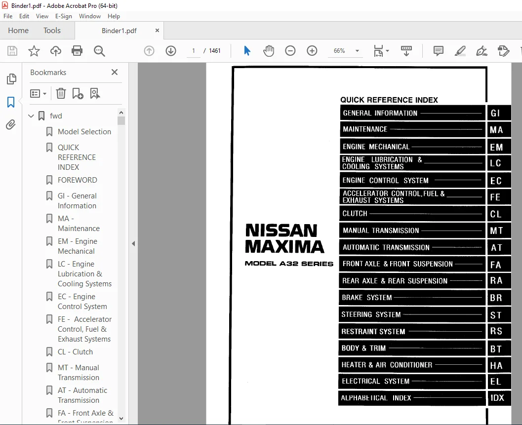
Pages : 1461
Downloadable :Yes
File Type : PDF
IMAGES PREVIEW OF THE MANUAL:
Questions? Email us: [email protected]
https://vimeo.com/852067056?share=copy
TABLE OF CONTENTS:
1996 NISSAN MAXIMA A32 Series Service Manual PDF DOWNLOAD
fwd............................................................................................................   1
	Model Selection............................................................................................   0
	QUICK REFERENCE INDEX......................................................................................   1
	FOREWORD...................................................................................................   2
	GI - General Information...................................................................................   0
	MA - Maintenance...........................................................................................   0
	EM - Engine Mechanical.....................................................................................   0
	LC - Engine Lubrication & Cooling Systems..................................................................   0
	EC - Engine Control System.................................................................................   0
	FE -  Accelerator Control, Fuel & Exhaust Systems..........................................................   0
	CL - Clutch................................................................................................   0
	MT - Manual Transmission...................................................................................   0
	AT - Automatic Transmission................................................................................   0
	FA - Front Axle & Front Suspension.........................................................................   0
	RA - Rear Axle & Rear Suspension...........................................................................   0
	BR - Brake System..........................................................................................   0
	ST - Steering System.......................................................................................   0
	RS - Restraint System......................................................................................   0
	BT - Body & Trim ..........................................................................................   0
	HA - Heater & Air  Conditioner.............................................................................   0
	EL - Electrical System.....................................................................................   0
	IDX - Alphabetical Index...................................................................................   1
	Foldout....................................................................................................   0
	Quick Reference Chart......................................................................................   3
AT.............................................................................................................   4
	QUICK REFERENCE INDEX......................................................................................   0
	TABLE OF CONTENTS..........................................................................................   4
	PREPARATION AND PRECAUTIONS................................................................................   6
		Special Service Tools..................................................................................   6
		Commercial Service Tools ..............................................................................   9
		Service Notice.........................................................................................  10
		Supplemental Restraint System (SRS) "AIR BAG"..........................................................  11
	DESCRIPTION................................................................................................  12
		Cross-sectional View...................................................................................  12
		Hydraulic Control Circuit..............................................................................  13
		Shift Mechanism........................................................................................  14
		Control System.........................................................................................  16
	TROUBLE DIAGNOSES..........................................................................................  18
		How to Perform Trouble Diagnoses for Quick and Accurate Repair.........................................  18
		Remarks................................................................................................  22
		Diagnostic Trouble Code (DTC) Chart....................................................................  23
		Diagnosis by CONSULT...................................................................................  25
		Preliminary Check......................................................................................  28
		A/T Electrical Parts Location..........................................................................  40
		Circuit Diagram for Quick Pinpoint Check...............................................................  41
		Wiring Diagram - AT -..................................................................................  42
		Self-diagnosis.........................................................................................  49
			DTC P0720 VEHICLE SPEED SENSOR A/T (REVOLUTION SENSOR) CIRCUIT CHECK...............................  55
			VEHICLE SPEED SENSOR MTR CIRCUIT CHECK.............................................................  57
			DTC P1705 THROTTLE POSITION SENSOR CIRCUIT CHECK...................................................  59
			DTC P0750 SHIFT SOLENOID VALVE A CIRCUIT CHECK.....................................................  61
			DTC P0755 SHIFT SOLENOID VALVE B CIRCUIT CHECK.....................................................  63
			DTC P1760 OVERRUN CLUTCH SOLENOID VALVE CIRCUIT CHECK..............................................  65
			DTC P0740 TORQUE CONVERTER CLUTCH SOLENOID VALVE CIRCUIT CHECK.....................................  67
			DTC P0710 A/T FLUID TEMPERATURE SENSOR CIRCUIT AND A/T CONTROL UNIT POWER SOURCE CIRCUIT CHECK.....  69
			DTC P0725 ENGINE SPEED SIGNAL CIRCUIT CHECK........................................................  72
			DTC P0745 LINE PRESSURE SOLENOID VALVE CIRCUIT CHECK...............................................  74
			DTC P0705 INHIBITOR, OVERDRIVE AND THROTTLE POSITION SWITCH CIRCUIT CHECK..........................  76
			DTC P0731 IMPROPER SHIFTING TO 1ST GEAR POSITION...................................................  80
			DTC P0732 IMPROPER SHIFTING TO 2ND GEAR POSITION...................................................  82
			DTC P0733 IMPROPER SHIFTING TO 3RD GEAR POSITION...................................................  84
			DTC P0734 IMPROPER SHIFTING TO 4TH GEAR POSITION OR IMPROPER TORQUE CONVERTER CLUTCH OPERATION.....  86
		Diagnostic Procedures for Symptoms.....................................................................  90
			Diagnostic Procedure 1.............................................................................  90
			Diagnostic Procedure 2.............................................................................  91
			Diagnostic Procedure 3.............................................................................  91
			Diagnostic Procedure 4.............................................................................  92
			Diagnostic Procedure 5.............................................................................  93
			Diagnostic Procedure 6.............................................................................  94
			Diagnostic Procedure 7.............................................................................  95
			Diagnostic Procedure 8.............................................................................  96
			Diagnostic Procedure 9.............................................................................  97
			Diagnostic Procedure 10............................................................................  98
			Diagnostic Procedure 11............................................................................  99
			Diagnostic Procedure 12............................................................................ 100
			Diagnostic Procedure 13............................................................................ 101
			Diagnostic Procedure 14............................................................................ 101
			Diagnostic Procedure 15............................................................................ 102
			Diagnostic Procedure 16............................................................................ 103
			Diagnostic Procedure 17............................................................................ 103
			Diagnostic Procedure 18............................................................................ 104
			Diagnostic Procedure 19............................................................................ 104
			Diagnostic Procedure 20............................................................................ 104
		Electrical Components Inspection....................................................................... 105
		Final Check............................................................................................ 112
		Symptom Chart.......................................................................................... 117
	TROUBLE DIAGNOSES - A/T Shift Lock System.................................................................. 120
		Description............................................................................................ 120
		Shift Lock System Electrical Parts Location............................................................ 120
		Wiring Diagram - SHIFT -............................................................................... 121
		Diagnostic Procedure................................................................................... 122
		Key Interlock Cable.................................................................................... 124
		Component Check........................................................................................ 125
	ON-VEHICLE SERVICE......................................................................................... 127
		Control Valve Assembly and Accumulator................................................................. 127
		Revolution Sensor Replacement.......................................................................... 128
		Inhibitor Switch Adjustment............................................................................ 128
		Control Cable Adjustment............................................................................... 129
		Differential Side Oil Seal Replacement................................................................. 129
	REMOVAL AND INSTALLATION................................................................................... 130
		Removal................................................................................................ 130
		Installation........................................................................................... 130
	MAJOR OVERHAUL............................................................................................. 132
		Oil Channel............................................................................................ 135
	DISASSEMBLY................................................................................................ 136
	REPAIR FOR COMPONENT PARTS................................................................................. 150
		Manual Shaft........................................................................................... 150
		Oil Pump............................................................................................... 152
		Control Valve Assembly................................................................................. 156
		Control Valve Upper Body............................................................................... 164
		Control Valve Lower Body............................................................................... 168
		Reverse Clutch......................................................................................... 170
		High Clutch............................................................................................ 173
		Forward Clutch and Overrun Clutch...................................................................... 177
		Low & Reverse Brake.................................................................................... 183
		Rear Internal Gear, Forward Clutch Hub and Overrun Clutch Hub.......................................... 185
		Output Shaft, Idler Gear, Reduction Pinion Gear and Bearing Retainer................................... 189
		Band Servo Piston Assembly............................................................................. 194
		Final Drive - RE4F04A.................................................................................. 199
		Final Drive - RE4F04V.................................................................................. 203
		ASSEMBLY............................................................................................... 208
		Assembly 1............................................................................................. 208
		Adjustment 1........................................................................................... 208
		Assembly 2............................................................................................. 213
		Adjustment 2........................................................................................... 219
		Assembly 3............................................................................................. 221
	SERVICE DATA AND SPECIFICATIONS (SDS)...................................................................... 227
		General Specifications................................................................................. 227
		Specifications and Adjustments......................................................................... 227
BR............................................................................................................. 234
	QUICK REFERENCE INDEX......................................................................................   0
	TABLE OF CONTENTS.......................................................................................... 234
	PRECAUTIONS AND PREPARATION................................................................................ 235
		Supplemental Restraint System (SRS) "AIR BAG".......................................................... 235
		Precautions............................................................................................ 235
		Commercial Service Tools............................................................................... 235
	BRAKE HYDRAULIC LINE/CONTROL VALVE......................................................................... 236
		Brake Hydraulic Line................................................................................... 236
		Dual Proportioning Valve............................................................................... 237
	CHECK AND ADJUSTMENT....................................................................................... 238
		Checking Brake Fluid Level............................................................................. 238
		Checking Brake Line.................................................................................... 238
		Changing Brake Fluid................................................................................... 238
		Bleeding Brake System.................................................................................. 238
	BRAKE PEDAL AND BRACKET.................................................................................... 239
		Removal and Installation............................................................................... 239
		Inspection............................................................................................. 239
		Adjustment............................................................................................. 239
	MASTER CYLINDER............................................................................................ 240
		Removal................................................................................................ 240
		Disassembly............................................................................................ 240
		Inspection............................................................................................. 241
		Assembly............................................................................................... 241
		Installation........................................................................................... 241
	BRAKE BOOSTER/VACUUM HOSE.................................................................................. 242
		Brake Booster.......................................................................................... 242
		Vacuum Hose............................................................................................ 243
	FRONT DISC BRAKE........................................................................................... 244
		Pad Replacement........................................................................................ 244
		Removal................................................................................................ 245
		Disassembly............................................................................................ 245
		Inspection - Caliper................................................................................... 246
		Inspection - Rotor..................................................................................... 246
		Assembly............................................................................................... 247
		Installation........................................................................................... 247
	REAR DISC BRAKE............................................................................................ 248
		Pad Replacement........................................................................................ 248
		Removal................................................................................................ 250
		Disassembly............................................................................................ 250
		Inspection - Caliper................................................................................... 251
		Inspection - Rotor..................................................................................... 252
		Assembly............................................................................................... 252
		Installation........................................................................................... 253
	PARKING BRAKE CONTROL...................................................................................... 254
		Removal and Installation............................................................................... 254
		Inspection............................................................................................. 255
		Adjustment............................................................................................. 255
	ANTI-LOCK BRAKE SYSTEM..................................................................................... 256
		Purpose................................................................................................ 256
		Operation.............................................................................................. 256
		ABS Hydraulic Circuit.................................................................................. 256
		System Components...................................................................................... 257
		System Description..................................................................................... 257
		Removal and Installation............................................................................... 258
		Wiring Diagram - ABS -................................................................................. 260
	TROUBLE DIAGNOSES.......................................................................................... 264
		Contents............................................................................................... 264
		Component Parts and Harness Connector Location......................................................... 274
	SERVICE DATA AND SPECIFICATIONS (SDS)...................................................................... 296
		General Specifications................................................................................. 296
		Inspection and Adjustment.............................................................................. 296
BT............................................................................................................. 297
	QUICK REFERENCE INDEX......................................................................................   0
	TABLE OF CONTENTS.......................................................................................... 297
	GENERAL SERVICING.......................................................................................... 298
		Precaution............................................................................................. 298
		Supplemental Restraint System (SRS) "AIR BAG".......................................................... 298
		Clip and Fastener...................................................................................... 299
	BODY END................................................................................................... 302
		Body Front End......................................................................................... 302
		Body Rear End and Opener............................................................................... 304
	DOOR....................................................................................................... 306
		Front Door............................................................................................. 306
		Rear Door.............................................................................................. 307
	INSTRUMENT PANEL........................................................................................... 308
	INTERIOR TRIM.............................................................................................. 311
		Side and Floor Trim.................................................................................... 311
		Door Trim.............................................................................................. 312
		Roof Trim.............................................................................................. 313
		Trunk Room Trim........................................................................................ 314
	EXTERIOR................................................................................................... 315
	SEAT....................................................................................................... 320
		Front Seat............................................................................................. 320
		Heated Seat............................................................................................ 321
		Rear Seat.............................................................................................. 322
	SUNROOF.................................................................................................... 323
	WINDSHIELD AND WINDOWS..................................................................................... 327
		Windshield and Rear Window............................................................................. 327
	MIRROR..................................................................................................... 328
		Door Mirror............................................................................................ 328
	BODY ALIGNMENT............................................................................................. 329
		Engine Compartment..................................................................................... 329
		Underbody.............................................................................................. 331
CL............................................................................................................. 333
	QUICK REFERENCE INDEX......................................................................................   0
	TABLE OF CONTENTS.......................................................................................... 333
	PRECAUTIONS AND PREPARATION................................................................................ 334
		Precautions............................................................................................ 334
		Special Service Tools.................................................................................. 334
	CLUTCH SYSTEM - Hydraulic Type............................................................................. 335
	INSPECTION AND ADJUSTMENT.................................................................................. 336
		Adjusting Clutch Pedal................................................................................. 336
		Bleeding Procedure..................................................................................... 336
	HYDRAULIC CLUTCH CONTROL................................................................................... 338
		Clutch Master Cylinder................................................................................. 338
		Operating Cyliinder.................................................................................... 339
	CLUTCH RELEASE MECHANISM................................................................................... 340
	CLUTCH DISC AND CLUTCH COVER............................................................................... 341
		Clutch Disc............................................................................................ 341
		Clutch Cover and Flywheel.............................................................................. 342
	SERVICE DATA AND SPECIFICATIONS............................................................................ 343
		General Specifications................................................................................. 343
		Inspection and Adjustment.............................................................................. 343
EC............................................................................................................. 344
	QUICK REFERENCE INDEX......................................................................................   0
	TABLE OF CONTENTS.......................................................................................... 344
	PRECAUTIONS AND PREPARATION................................................................................ 347
		Supplemental Restraint System (SRS) "AIR BAG".......................................................... 347
		Precautions for On-Board Diagnostic (OBD) System of Engine and A/T..................................... 347
		Engine Fuel & Emission Control System.................................................................. 348
		Precautions............................................................................................ 349
	ENGINE AND EMISSION CONTROL OVERALL SYSTEM................................................................. 351
		Circuit Diagram........................................................................................ 351
		System Diagram......................................................................................... 352
		ECCS Component Parts Location.......................................................................... 353
		Vacuum Hose Drawing.................................................................................... 356
		System Chart........................................................................................... 357
	ENGINE AND EMISSION BASIC CONTROL SYSTEM DESCRIPTION....................................................... 358
		Multiport Fuel Injection (MFI) System.................................................................. 358
		Electronic Ignition (EI) System........................................................................ 361
		Air Conditioning Cut Control........................................................................... 362
		Fuel Cut Control (at no load & high engine speed)...................................................... 363
	EVAPORATIVE EMISSION SYSTEM................................................................................ 365
		Description............................................................................................ 365
		Inspection............................................................................................. 365
		Evaporative Emission Line Drawing...................................................................... 367
	POSITIVE CRANKCASE VENTILATION............................................................................. 369
		Description............................................................................................ 369
		Inspection............................................................................................. 369
	BASIC SERVICE PROCEDURE.................................................................................... 370
		Fuel Pressure Release.................................................................................. 370
		Fuel Pressure Check.................................................................................... 370
		Injector Removal and Installation...................................................................... 371
		Fast Idle Cam (FIC) Inspection and Adjustment.......................................................... 372
		Direct Ignition System - How to Check Idle Speed and Ignition Timing................................... 373
		Idle Speed/Ignition Timing/Idle Mixture Ratio Adjustment............................................... 375
	ON-BOARD DIAGNOSTIC SYSTEM DESCRIPTION..................................................................... 382
		Introduction........................................................................................... 382
		Two Trip Detection Logic............................................................................... 382
		Diagnostic Trouble Code (DTC).......................................................................... 382
		Freeze Frame Data...................................................................................... 384
		Malfunction Indicator Lamp (MIL)....................................................................... 384
		OBD System Operation Chart............................................................................. 389
		CONSULT................................................................................................ 394
		Generic Scan Tool (GST)................................................................................ 407
	TROUBLE DIAGNOSIS - Introduction........................................................................... 409
		Introduction........................................................................................... 409
		Diagnostic Worksheet................................................................................... 410
	TROUBLE DIAGNOSIS - Work Flow.............................................................................. 411
		Work Flow.............................................................................................. 411
		Description for Work Flow.............................................................................. 412
	TROUBLE DIAGNOSIS - Basic Inspection....................................................................... 413
		Basic Inspection....................................................................................... 413
	TROUBLE DIAGNOSIS - General Description.................................................................... 415
		Diagnostic Trouble Code (DTC) Chart.................................................................... 415
		Fail-Safe Chart........................................................................................ 430
		Symptom Matrix Chart................................................................................... 431
		CONSULT Reference Value in Data Monitor Mode........................................................... 434
		Major Sensor Reference Graph in Data Monitor Mode...................................................... 437
		ECM Terminals and Reference Value...................................................................... 439
	TROUBLE DIAGNOSIS FOR POWER SUPPLY......................................................................... 447
		Main Power Supply and Ground Circuit................................................................... 447
	DTC P0100, Mass Air Flow Sensor (MAFS) (DTC: 0102)......................................................... 451
	DTC P0105, Absolute Pressure Sensor (DTC: 0803)............................................................ 456
	DTC P0110, Intake Air Temperature Sensor (DTC: 0401)....................................................... 463
	DTC P0115, Engine Coolant Temperature Sensor (ECTS) (DTC: 0103)............................................ 468
	DTC P0120, Throttle Position Sensor (DTC: 0403)............................................................ 472
	DTC P0125, Engine Coolant Temperature (ECT) Sensor (DTC: 0908)............................................. 477
	DTC P0130, Front Heated Oxygen Sensor (Front HO2S) (Right bank) (DTC: 0503)................................ 482
	DTC P0130, P0150, Closed Loop Control (DTC: 0307, 0308).................................................... 487
	DTC P0135, Front Heated Oxygen Sensor Heater (Right bank) (DTC: 0901)...................................... 489
	DTC P0136, Rear Heated Oxygen Sensor (Rear HO2S) (DTC: 0707)............................................... 492
	DTC P0150, Front Heated Oxygen Sensor (Front HO2S) (Left bank) (DTC: 0303)................................. 497
	DTC P0155, Front Heated Oxygen Sensor heater (Left bank) (DTC: 1001)....................................... 502
	DTC P0171, Fuel Injection System Function (Right bank) (Lean side) (DTC: 01115)............................ 505
	DTC P0172, Fuel Injection System Function (Right bank) (Rich side) (DTC: 0114)............................. 510
	DTC P0174, Fuel Injection System Function (Left bank) (Lean side) (DTC: 0210).............................. 515
	DTC P0175, Fuel Injection System Function (Left bank) (Rich side) (DTC: 0209).............................. 520
	DTC P0180, Tank Fuel Temperature Sensor (9402)............................................................. 525
	DTC P0300 - P0306, No. 1 - 6 Cylinder Misfire, Multiple Cylinder Misfire (DTC: 0701 - 0603)................ 528
	DTC P0325, Knock Sensor (KS) (DTC: 0304)................................................................... 532
	DTC P0335, Crankshaft Positions Sensor (CKPS) (POS) (DTC: 0802)............................................ 535
	DTC P0340, Camshaft Position Sensor (CMPS) (PHASE) (DTC: 0101)............................................. 540
	DTC P0400, EGR Function (DTC: 0302)........................................................................ 544
	DTC P0402, EGRC-BPT Valve Function (DTC: 0306)............................................................. 553
	DTC P0420, P0430, Three Way Catalyst Function (DTC: 0702, 0703)............................................ 555
	DTC P0440, Evaporative Emission (EVAP) Control System (Small Leak) (DTC: 0705)............................. 558
	DTC P0443, Evaporative Emission (EVAP) Canister Purge Control Valve/Solenoid Valve (DTC: 0807)............. 568
	DTC P0446, Evaporative Emission (EVAP) Canister Vent Control Valve (DTC: 0903)............................. 576
	DTC P0450, Evaporative Emission (EVAP) Control System Pressure Sensor (DTC: 004)........................... 581
	DTC P0500, Vehicle Speed Sensor (VSS) (DTC: 0104).......................................................... 585
	DTC P0505, Idle Air Control Valve (IACV) - Auxiliary Air Control (AAC) Valve (DTC: 0205)................... 589
	DTC P0510, Closed Throttle Position Switch (DTC: 0203)..................................................... 595
	DTC P0600, A/T Control (DTC: 0504)......................................................................... 599
	DTC P0605, Engine Control Module (ECM) - ECCS Control Module (DTC: 0301)................................... 602
	DTC P0705, Park/Neutral Position Switch (DTC: 1003)........................................................ 604
	DTC P1105, Manifold Absolute Pressure (MAP)/Barometric Pressure (BARO) Switch Solenoid Valve (DTC 1302).... 608
	DTC P1220, Fuel Pump Control Module (FPCM) (DTC: 1305)..................................................... 614
	DTC P1320, Ignition Signal (DTC: 0201)..................................................................... 620
	DTC P1335, Crankshaft Position Sensor (CKPS) (REF) (DTC: 0407)............................................. 626
	DTC P1336, Crankshaft Position Sensor (CKPS) (POS) (COG) ( DTC: 0905)...................................... 630
	DTC P1400, EGRC-Solenoid Valve (DTC: 1005)................................................................. 635
	DTC P1401, EGR Temperature Sensor (DTC: 0305).............................................................. 638
	DTC P1441, Vacuum Cut Valve Bypass Valve (DTC: 0801)....................................................... 643
	DTC P1445, Evaporative Emission (EVAP) Canister Purge Volume Control Valve (DTC: 1008)..................... 648
	DTC P1447, Evaporative Emission (EVAP) Control System Purge Flow Monitoring (DTC: 0111).................... 654
	DTC P1605, A/T Diagnosis Communication Line (DTC: 0804).................................................... 661
	DTC P1900, Cooling Fan (DTC: 1308)......................................................................... 664
	TROUBLE DIAGNOSIS FOR NON-DETECTABLE ITEMS................................................................. 676
		Injector............................................................................................... 676
		Start Signal........................................................................................... 680
		Fuel Pump Control...................................................................................... 682
		Front Engine Mounting Control.......................................................................... 686
		Power Steering Oil Pressure Switch..................................................................... 689
		IAVC-FICD Solenoid Valve............................................................................... 693
		Electrical Load Signal................................................................................. 697
		MIL & Data Link Connectors............................................................................. 700
	TROUBLE DIAGNOSIS - Index.................................................................................. 701
		Alphabetical & P No. Index for DTC..................................................................... 701
	SERVICE DATA AND SPECIFICATIONS (SDS)...................................................................... 703
		General Specifications................................................................................. 703
		Inspection and Adjustment.............................................................................. 703
EL............................................................................................................. 705
	QUICK REFERENCE INDEX......................................................................................   0
	TABLE OF CONTENTS.......................................................................................... 705
	PRECAUTIONS................................................................................................ 708
		Supplemental Restraint System (SRS) "AIR BAG".......................................................... 708
	HARNESS CONNECTOR.......................................................................................... 709
		Description............................................................................................ 709
	STANDARDIZED RELAY......................................................................................... 710
		Description............................................................................................ 710
	POWER SUPPLY ROUTING....................................................................................... 711
		Wiring Diagram - POWER................................................................................. 711
		Schematic.............................................................................................. 723
		Fuse................................................................................................... 724
		Fusible Link........................................................................................... 724
		Circuit Breaker Inspection............................................................................. 724
	BATTERY.................................................................................................... 725
		How to Handle Battery.................................................................................. 725
		Service Data and Specifications (SDS).................................................................. 728
	STARTING SYSTEM............................................................................................ 729
		System Description..................................................................................... 729
		Wiring Diagram - START -............................................................................... 730
		Construction........................................................................................... 734
		Removal and Installation............................................................................... 734
		Pinion/Clutch Check.................................................................................... 735
		Service Data and Specifications (SDS).................................................................. 735
	CHARGING SYSTEM............................................................................................ 736
		System Description..................................................................................... 737
		Wiring Diagram - CHARGE -.............................................................................. 737
		Construction........................................................................................... 738
		Removal and Installation............................................................................... 738
		Trouble DIagnoses...................................................................................... 739
		Service Data and Specifications (SDS).................................................................. 740
	COMBINATION SWITCH......................................................................................... 741
		Combination Switch/Check............................................................................... 741
		Combination Switch/Replacement......................................................................... 742
		Steering Switch/Check.................................................................................. 743
	HEADLAMP................................................................................................... 744
		System Description (For USA)........................................................................... 744
		Wiring Diagram - H/LAMP -.............................................................................. 745
		Trouble Diagnoses (For USA)............................................................................ 746
	HEADLAMP - Daytime Light System -.......................................................................... 747
		System Description (For Canada)........................................................................ 747
		Operation (For Canada)................................................................................. 748
		Schematic.............................................................................................. 748
		Wiring Diagram - DTRL -................................................................................ 749
		Trouble Diagnoses (For Canada)......................................................................... 752
	HEADLAMP................................................................................................... 754
		Bulb Replacement....................................................................................... 754
		Aiming Adjustment...................................................................................... 754
	EXTERIOR LAMP.............................................................................................. 756
		Back-up Lamp/Wiring Diagram - BACK/L -................................................................. 756
		Clearance, License and Tail Lamps/Wiring Diagram - TAIL/L -............................................ 757
		Front Fog Lamp/System Description...................................................................... 759
		Front Fog Lamp/Wiring Diagram - F/FOG -................................................................ 760
		Front Fog Lamp Aiming Adjustment....................................................................... 761
		Turn Signal and Hazard Warning Lamps/System Description................................................ 762
		Turn Signal and Hazard Warning Lamps/Wiring Diagram - TURN -........................................... 763
		Turn Signal and Hazard Warning Lamps/Schematic......................................................... 766
		Turn Signal and Hazard Warning Lamps/Trouble Diagnoses................................................. 767
		Stop Lamp/Wiring Diagram - STOP/L...................................................................... 768
		Cornering Lamp/System Description...................................................................... 770
		Cornering Lamp/Wiring Diagram - CORNER -............................................................... 771
		Combination Flasher Unit Check......................................................................... 773
		Bulb Specifications.................................................................................... 773
	INTERIOR LAMP.............................................................................................. 774
		Illumination/System Description........................................................................ 774
		Spot and Trunk Room Lamps/System Description........................................................... 774
		Illumination/Wiring Diagram - ILL -.................................................................... 775
		Illumiination/Schematic................................................................................ 779
		Spot and Trunk Room Lamp/Wiring Diagram - INT/L -...................................................... 780
		Bulb Specifications.................................................................................... 781
	METERS AND GAUGES.......................................................................................... 782
		System Description..................................................................................... 782
		Combination Meter...................................................................................... 783
		Speedometer, Tachometer, Temp. and Fuel Gauges/Wiring Diagram - METER -................................ 784
		Inspection/Fuel Gauge and Water Temperature Gauge...................................................... 786
		Fuel Tank Gauge Unit Check............................................................................. 787
		Thermal Transmitter Check.............................................................................. 787
		Vehicle Speed Sensor Signal Check...................................................................... 787
	WARNING LAMPS.............................................................................................. 788
		Wiring Diagram - WARN -................................................................................ 788
		Schematic.............................................................................................. 793
		Fuel Warning Lamp Sensor Check......................................................................... 794
		Oil Pressure Switch Check.............................................................................. 794
		Diode Check............................................................................................ 794
	WIPER AND WASHER........................................................................................... 795
		System Description..................................................................................... 795
		Front Wiper and Washer/Wiring Diagram - WIPER -........................................................ 797
		Installation........................................................................................... 799
		Wiper Linkage.......................................................................................... 800
		Washer Nozzle Adjustment............................................................................... 801
		Check Valve............................................................................................ 801
	HORN, CIGARETTE LIGHTER, CLOCK............................................................................. 802
		Wiring Diagram - HORN -................................................................................ 802
	REAR WINDOW DEFOGGER....................................................................................... 804
		Wiring Diagram - DEF -................................................................................. 804
		Filament Check......................................................................................... 806
		Filament Repair........................................................................................ 807
	AUDIO AND POWER ANTENNA.................................................................................... 808
		Audio/System Description............................................................................... 808
		Audio/Wiring Diagram - AUDIO -......................................................................... 809
		Power Antenna/System Description....................................................................... 818
		Power Antenna/Wiring Diagram - P/ANT -................................................................. 819
		Trouble Diagnoses...................................................................................... 820
		Location of Antenna.................................................................................... 822
		Antenna Rod Replacement................................................................................ 823
		Window Antenna Repair.................................................................................. 824
	TELEPHONE.................................................................................................. 825
		Telephone Pre Wire/Wiring Diagram - PHONE -............................................................ 825
	ELECTRIC SUNROOF........................................................................................... 826
		Sunroof/Wiring Diagram - SROOF -....................................................................... 826
	POWER SEAT................................................................................................. 827
		Power Seat/Wiring Diagram - SEAT -..................................................................... 827
	HEATED SEAT................................................................................................ 829
		Heated Seat/Wiring Diagram - HSEAT -................................................................... 829
	POWER DOOR MIRROR.......................................................................................... 830
		Wiring Diagram - MIRROR -.............................................................................. 830
	TRUNK LID AND FUEL FILLER LID OPENER....................................................................... 831
		Wiring Diagram - TLID -................................................................................ 831
	AUTOMATIC SPEED CONTROL DEVICE (ASCD)...................................................................... 832
		Component Parts and Harness Connector Location......................................................... 832
		System Description..................................................................................... 833
		Wiring Diagram - ASCD -................................................................................ 835
		Schematic.............................................................................................. 840
		Trouble Diagnoses...................................................................................... 842
	IVMS (LAN) - SYSTEM DESCRIPTION............................................................................ 857
		Overall Description.................................................................................... 857
		Component Parts Location............................................................................... 859
		System Diagram......................................................................................... 860
		Sleep/Wake-up Control.................................................................................. 861
	IVMS (LAN) - TROUBLE DIAGNOSES SYSTEM...................................................................... 862
		CONSULT................................................................................................ 862
		On-board Diagnosis..................................................................................... 868
		On-board Diagnosis - Mode I (IVMS communication diagnosis)............................................. 869
		On-board Diagnosis - Mode II (Switch monitor).......................................................... 871
		Body Control Module (BCM).............................................................................. 873
		Local Control Units (LCUs)............................................................................. 876
		Main Power Supply, Ground and Communication Circuits/Wiring Diagram - COMM -........................... 884
		Power Supply and Ground Circuit Check.................................................................. 887
	POWER WINDOW - IVMS........................................................................................ 889
		System Description..................................................................................... 889
		Wiring Diagram - WINDOW -.............................................................................. 890
		Schematic.............................................................................................. 894
		On-board Diagnosis - Mode IV (Power window monitor).................................................... 895
		Trouble Diagnoses...................................................................................... 897
	POWER DOOR LOCK - IVMS..................................................................................... 901
		System Description..................................................................................... 901
		Wiring Diagram - D/LOCK -.............................................................................. 902
		Schematic.............................................................................................. 906
		CONSULT................................................................................................ 907
		On-board Diagnosis - Mode III (Power door lock operation).............................................. 910
		Trouble Diagnoses...................................................................................... 912
	MULTI-REMOTE CONTROL SYSTEM - IVMS......................................................................... 919
		System Description..................................................................................... 919
		Wiring Diagram - MULTI -............................................................................... 921
		Schematic.............................................................................................. 928
		Trouble Diagnoses...................................................................................... 929
		Replacing Remote Controller or Multi-Remote- Control Unit (LCU05)...................................... 934
	TIME CONTROL SYSTEM - IVMS................................................................................. 935
		System Description..................................................................................... 935
		Wiring Diagram - TIME -................................................................................ 937
		Trouble Diagnoses...................................................................................... 941
	THEFT WARNING SYSTEM - IVMS................................................................................ 949
		Component Parts and Harness Connector Location......................................................... 949
		Schematic.............................................................................................. 950
		Wiring Diagram - THEFT -............................................................................... 952
		Trouble Diagnoses...................................................................................... 959
	ILLUMINATION  - IVMS....................................................................................... 972
		System Description..................................................................................... 972
		Wiring Diagram - SW/ILL -.............................................................................. 973
		Trouble Diagnoses...................................................................................... 974
	INTERIOR LAMP ON-OFF CONTROL - IVMS........................................................................ 975
		System Description..................................................................................... 975
		Wiring Diagram - ROOM/L................................................................................ 976
		Trouble Diagnoses...................................................................................... 979
	STEP LAMP - IVMS........................................................................................... 981
		System Description..................................................................................... 981
		Wiring Diagram - STEP/L -.............................................................................. 982
		Trouble Diagnoses...................................................................................... 984
	LOCATION OF ELECTRICAL UNITS............................................................................... 985
		Engine Compartment..................................................................................... 985
		Passenger Compartment.................................................................................. 986
		Luggage Compartment.................................................................................... 987
	HARNESS LAYOUT............................................................................................. 988
		Outline................................................................................................ 988
		Engine Room Harness.................................................................................... 989
		Main Harness........................................................................................... 992
		Engine Control Harness................................................................................. 994
		Body Harness........................................................................................... 996
		Body No. 2 Harness and Tail Harness.................................................................... 998
		Room Lamp Harness...................................................................................... 999
		Door Harness (LH side).................................................................................1000
		Door Harness (RH side).................................................................................1001
		Air Bag Harness........................................................................................1002
	GROUND DISTRIBUTION........................................................................................1003
	SUPER MULTIPLE JUNCTION (SMJ)..............................................................................   0
		Terminal Arrangement...................................................................................   1
	FUSE BLOCK - Junction Box (J/B)............................................................................   2
	FUSE AND FUSIBLE LINK BOX..................................................................................   3
		Terminal Arrangement...................................................................................   3
	ELECTRICAL UNITS...........................................................................................   4
		Terminal Arrangement...................................................................................   4
	JOINT CONNECTOR (J/C)......................................................................................   5
		Terminal Arrangement...................................................................................   5
EM.............................................................................................................1007
	QUICK REFERENCE INDEX......................................................................................   0
	TABLE OF CONTENTS..........................................................................................1007
	PRECAUTIONS................................................................................................1008
		Parts Requiring Angular Tightening.....................................................................1008
		Liquid Gasket Application Procedure....................................................................1008
	PREPARATION................................................................................................1009
		Special Service Tools..................................................................................1009
		Commercial Service Tools...............................................................................1011
	OUTER COMPONENT PARTS......................................................................................1012
	COMPRESSION PRESSURE.......................................................................................1016
		Measurement of Compression Pressure....................................................................1016
	OIL PAN....................................................................................................1017
		Removal................................................................................................1017
		Installation...........................................................................................1020
	TIMING CHAIN...............................................................................................1023
		Removal................................................................................................1025
		Inspection.............................................................................................1032
		Installation...........................................................................................1032
	OIL SEAL REPLACEMENT.......................................................................................1037
	CYLINDER HEAD..............................................................................................1040
		Removal................................................................................................1041
		Disassembly............................................................................................1041
		Inspection.............................................................................................1043
		Assembly...............................................................................................1047
		Installation...........................................................................................1047
	VALVE CLEARANCE............................................................................................1053
		Checking...............................................................................................1053
		Adjusting..............................................................................................1054
	ENGINE REMOVAL.............................................................................................1057
		Removal................................................................................................1058
		Installation...........................................................................................1059
	CYLINDER BLOCK.............................................................................................1060
		Disassembly............................................................................................1061
		Inspection.............................................................................................1061
		Assembly...............................................................................................1068
	SERVICE DATA AND SPECIFICATIONS (SDS)......................................................................1071
		General Specifications.................................................................................1071
		Inspection and Adjustment..............................................................................1071
FA.............................................................................................................1079
	QUICK REFERENCE INDEX......................................................................................   0
	TABLE OF CONTENTS..........................................................................................1079
	PRECAUTIONS AND PREPARATION................................................................................1080
		Precautions............................................................................................1080
		Special Service Tools..................................................................................1080
		Commercial Service Tools...............................................................................1081
	FRONT SUSPENSION SYSTEM....................................................................................1082
	ON-VEHICLE SERVICE.........................................................................................1083
		Front Axle and Front Suspension Parts..................................................................1083
		Front Wheel Bearing....................................................................................1084
		Front Wheel Alignment..................................................................................1084
		Drive Shaft............................................................................................1085
	FRONT AXLE.................................................................................................1086
		Wheel Hub and Knuckle..................................................................................1086
		Drive Shaft............................................................................................1090
	FRONT SUSPENSION...........................................................................................1098
		Coil Spring and Strut Assembly.........................................................................1099
		Stabilizer Bar.........................................................................................1100
		Transverse Link and Lower Ball Joint...................................................................1101
	SERVICE DATA AND SPECIFICATIONS (SDS)......................................................................1103
		General Specifications.................................................................................1103
		Inspection and Adjustment..............................................................................1104
FE.............................................................................................................1105
	QUICK REFERENCE INDEX......................................................................................   0
	TABLE OF CONTENTS..........................................................................................1105
	PREPARATION/ACCELERATOR CONTROL SYSTEM.....................................................................1106
		Special Service Tool...................................................................................1106
		Adjusting Accelerator Wire.............................................................................1106
	FUEL SYSTEM................................................................................................1107
	EXHAUST SYSTEM.............................................................................................1108
Foldout........................................................................................................1109
	QUICK REFERENCE INDEX......................................................................................   0
	ELECTRICAL SYSTEM..........................................................................................   2
	SUPER MULTIPLE JUNCTION (SMJ)..............................................................................1109
		Terminal Arrangement...................................................................................1110
	FUSE BLOCK - Junction Box (J/B)............................................................................1111
	FUSE AND FUSIBLE LINK BOX..................................................................................1112
		Terminal Arrangement...................................................................................1112
	ELECTRICAL UNITS...........................................................................................1113
		Terminal Arrangement...................................................................................1113
	JOINT CONNECTOR (J/C)......................................................................................1114
		Terminal Arrangement...................................................................................1114
GI.............................................................................................................1115
	QUICK REFERENCE INDEX......................................................................................   0
	TABLE OF CONTENTS..........................................................................................1115
	PRECAUTIONS................................................................................................1116
		Precautions for Supplemental Restraint System (SRS) "AIR BAG"..........................................1116
		General Precautions....................................................................................1116
		Precautions for Multiport Fuel Injection System or ECCS Engine.........................................1118
		Precautions for Three Way Catalyst.....................................................................1118
		Engine Oils............................................................................................1118
		Precautions for Fuel...................................................................................1119
		Precautions for Air Conditioning.......................................................................1119
	HOW TO USE THIS MANUAL.....................................................................................1120
	HOW TO READ WIRING DIAGRAMS................................................................................1122
		Sample/Wiring Diagram - EXAMPL -.......................................................................1122
		Description............................................................................................1124
		Wiring Diagram Codes (Cell Codes)......................................................................1130
	HOW TO PERFORM EFFICIENT DIAGNOSIS FOR AN ELECTRICAL INCIDENT..............................................1132
		Work Flow..............................................................................................1132
		Incident Simulation Tests..............................................................................1133
		Circuit Inspection.....................................................................................1137
	HOW TO FOLLOW FLOW CHART IN TROUBLE DIAGNOSES..............................................................1143
	CONSULT CHECKING SYSTEM....................................................................................1146
		Function and System Application........................................................................1146
		Lithium Battery Replacement............................................................................1146
		Checking Equipment.....................................................................................1146
	IDENTIFICATION INFORMATION.................................................................................1147
		Model Variation........................................................................................1147
		Identification Number..................................................................................1148
		Dimensions.............................................................................................1150
		Wheels and Tires.......................................................................................1150
	LIFTING POINTS AND TOW TRUCK TOWING........................................................................1151
		Preparation............................................................................................1151
		Board-on Lift..........................................................................................1151
		Garage Jack and Safety Stand...........................................................................1152
		2-pole Lift............................................................................................1153
		Tow Truck Towing.......................................................................................1154
	TIGHTENING TORQUE OF STANDARD BOLTS........................................................................1155
	SAE J1930 TERMINOLOGY LIST.................................................................................1156
		SAE J1930 Terminology List.............................................................................1156
HA.............................................................................................................1160
	QUICK REFERENCE INDEX......................................................................................   0
	TABLE OF CONTENTS..........................................................................................1160
	MANUAL AND AUTO............................................................................................1162
		PRECAUTIONS AND PREPARATION............................................................................1162
			Supplemental Restraint System (SRS) "AIR BAG"......................................................1162
			General Refrigerant Precautions....................................................................1162
			Precautions for Refrigerant Connection.............................................................1163
			Precautions for Servicing Compressor...............................................................1164
			Special Service Tools..............................................................................1164
			HFC-134a (R-134a) Service Tools and Equipment......................................................1165
			Precautions for Service Equipment..................................................................1167
		DESCRIPTION............................................................................................1169
			Refrigeration Cycle................................................................................1169
			V-6 Variable Displacement Compressor...............................................................1170
			Component Layout...................................................................................1174
			Discharge Air Flow.................................................................................1175
	MANUAL.....................................................................................................1176
		DESCRIPTION............................................................................................1176
			Control Operation..................................................................................1176
		TROUBLE DIAGNOSES......................................................................................1177
			Contents...........................................................................................1177
	MANUAL AND AUTO............................................................................................1188
		TROUBLE DIAGNOSES......................................................................................1188
			Performance Test Diagnoses.........................................................................1188
			Performance Chart..................................................................................1190
			Trouble Diagnoses for Abnormal Pressure............................................................1191
	MANUAL.....................................................................................................1195
		TROUBLE DIAGNOSES......................................................................................1195
			Wiring Diagram - A/C, M -..........................................................................1198
	AUTO.......................................................................................................1218
		DESCRIPTION............................................................................................1218
			Introduction.......................................................................................1218
			Features...........................................................................................1218
			Control Operation..................................................................................1219
		TROUBLE DIAGNOSES......................................................................................1221
			Contents...........................................................................................1221
			Wiring Diagram - A/C, A -..........................................................................1250
		SYSTEM DESCRIPTION.....................................................................................1276
			Overview of Control System.........................................................................1276
			Control System Input Components....................................................................1277
			Control System Automatic Amplifier (Auto amp.).....................................................1279
			Control System Output Components...................................................................1280
	MANUAL AND AUTO............................................................................................1288
		SERVICE PROCEDURES.....................................................................................1288
			HFC-134a (R-134a) Service Procedure................................................................1288
			Maintenance of Lubricant Quantity in Compressor....................................................1290
			Refrigerant Lines..................................................................................1292
			Compressor Mounting................................................................................1293
			Belt Tension.......................................................................................1293
			Fast Idle Control Device (FICD)....................................................................1293
			Compressor.........................................................................................1294
			Compressor Clutch..................................................................................1294
	SERVICE DATA AND SPECIFICATIONS (SDS)......................................................................1298
		General Specifications.................................................................................1298
		Inspection and Adjustment..............................................................................1298
IDX............................................................................................................1299
	QUICK REFERENCE INDEX......................................................................................   0
LC.............................................................................................................1306
	QUICK REFERENCE INDEX......................................................................................   0
	TABLE OF CONTENTS..........................................................................................1306
	PRECAUTIONS AND PREPARATION................................................................................1307
		Liquid Gasket Application Procedure....................................................................1307
		Special Service Tools..................................................................................1307
	ENGINE LUBRICATION SYSTEM..................................................................................1308
		Lubrication Circuit....................................................................................1308
		Oil Pressure Check.....................................................................................1309
		Oil Pump...............................................................................................1309
	ENGINE COOLING SYSTEM......................................................................................1312
		Cooling Circuit........................................................................................1312
		System Check...........................................................................................1313
		Water Pump.............................................................................................1313
		Thermostat.............................................................................................1318
		Radiator...............................................................................................1319
		Cooling Fan Control System.............................................................................1319
		Overheating Cause Analysis.............................................................................1320
	SERVICE DATA AND SPECIFICATIONS............................................................................1321
		Engine Lubrication System..............................................................................1321
		Engine Cooling System..................................................................................1321
MA.............................................................................................................1322
	QUICK REFERENCE INDEX......................................................................................   0
	TABLE OF CONTENTS..........................................................................................1322
	PRECAUTIONS AND PREPARATION................................................................................1323
		Supplemental Restraint System (SRS) "AIR BAG"..........................................................1323
		Special Service Tool...................................................................................1323
	GENERAL MAINTENANCE........................................................................................1324
	PERIODIC MAINTENANCE.......................................................................................1326
		Schedule 1.............................................................................................1327
		Schedule 2.............................................................................................1328
	RECOMMENDED FLUIDS AND LUBRICANTS..........................................................................1329
		Fluids and Lubricants..................................................................................1329
		SAE Viscosity Number...................................................................................1329
		Anti-freeze Coolant Mixture Ratio......................................................................1330
	ENGINE MAINTENANCE.........................................................................................1331
		Checking Drive Belts...................................................................................1331
		Changing Engine Coolant................................................................................1332
		Checking Fuel Lines....................................................................................1333
		Changing Fuel Filter...................................................................................1333
		Changing Air Cleaner Filter............................................................................1334
		Changing Engine Oil....................................................................................1335
		Changing Oil Filter....................................................................................1335
		Changing Spark Plugs...................................................................................1336
		Checking EVAP Vapor Purge Lines........................................................................1337
	CHASSIS AND BODY  MAINTENANCE..............................................................................1338
		Checking Exhaust System................................................................................1338
		Checking Clutch Fluid Level and Leaks..................................................................1338
		Checking M/T Oil.......................................................................................1338
		Changing M/T Oil.......................................................................................1338
		Checking A/T Fluid.....................................................................................1339
		Changing A/T Fluid.....................................................................................1339
		Balalncing Wheels......................................................................................1339
		Tire Rotation..........................................................................................1340
		Checking Brake Fluid Level and Leaks...................................................................1340
		Checking Brake Lines and Cables........................................................................1340
		Checking Disc Brake....................................................................................1340
		Checking Steering Gear and LInkage.....................................................................1341
		Checking Power Steering Fluid and Lines................................................................1341
		Lubricating Locks, Hinges and Hood Latches.............................................................1342
		Checking Seat Belts, Buckles, Retractors, Anchors and Adjusters........................................1342
	SERVICE DATA AND SPECIFICATIONS (SDS)......................................................................1343
		Engine Maintenance.....................................................................................1343
		Chassis and Body Maintenance...........................................................................1343
MT.............................................................................................................1344
	QUICK REFERENCE INDEX......................................................................................   0
	TABLE OF CONTENTS..........................................................................................1344
	PREPARATION................................................................................................1345
		Special Service Tools..................................................................................1345
		Commercial Service Tools...............................................................................1347
	ON-VEHICLE SERVICE/REMOVAL AND INSTALLATION................................................................1348
		Replacing Oil Seal.....................................................................................1348
		Position Switch Check..................................................................................1349
		Viscous Coupling Check.................................................................................1349
		Removal................................................................................................1349
		Installation...........................................................................................1350
	TRANSAXLE GEAR CONTROL.....................................................................................1351
	MAJOR OVERHAUL.............................................................................................1352
		Case Components........................................................................................1352
		Gear Components........................................................................................1353
		Shift Control Components...............................................................................1354
	DISASSEMBLY................................................................................................1355
	REPAIR FOR COMPONENT PARTS.................................................................................1358
		Input Shaft and Gears..................................................................................1358
		Mainshaft and Gears....................................................................................1363
		Final Drive............................................................................................1367
		Shift Control Components...............................................................................1373
		Case Components........................................................................................1373
	ADJUSTMENT.................................................................................................1374
		Input Shaft End Play and Differential Side Bearing Preload.............................................1374
		Mainshaft Bearing Preload..............................................................................1375
	ASSEMBLY...................................................................................................1378
	SERVICE DATA AND SPECIFICATIONS (SDS)......................................................................1382
		General Specifications.................................................................................1382
		Inspection and Adjustment..............................................................................1382
RA.............................................................................................................1387
	QUICK REFERENCE INDEX......................................................................................   0
	TABLE OF CONTENTS..........................................................................................1387
	PRECAUTIONS AND PREPARATION................................................................................1388
		Precautions............................................................................................1388
		Preparation............................................................................................1388
	REAR SUSPENSION SYSTEM.....................................................................................1389
	ON-VEHICLE SERVICE.........................................................................................1390
		Rear Axle and Rear Suspension Parts....................................................................1390
		Rear Wheel Bearing.....................................................................................1390
		Rear Wheel Alignment...................................................................................1391
	REAR AXLE..................................................................................................1392
		Wheel Hub..............................................................................................1392
	REAR SUSPENSION............................................................................................1395
		Removal and Installation...............................................................................1396
		Coil Spring and Shock Absorber.........................................................................1396
		Torsion Beam, Lateral Link and Control Rod.............................................................1398
	SERVICE DATA AND SPECIFICATIONS (SDS)......................................................................1399
		General Specifications.................................................................................1399
		Inspection and Adjustment..............................................................................1399
RS.............................................................................................................1400
	QUICK REFERENCE INDEX......................................................................................   0
	TABLE OF CONTENTS..........................................................................................1400
	PRECAUTION.................................................................................................1401
		Supplemental Restraint system (SRS) "AIR BAG"..........................................................1401
	SEAT BELTS.................................................................................................1402
		Front Seat Belt........................................................................................1402
		Rear Seat Belt.........................................................................................1403
	SUPPLEMENTAL RESTRAINT SYSTEM (SRS)........................................................................1404
		Precautions for SRS "Air Bag" Service..................................................................1404
		Special Service Tools..................................................................................1404
		Description............................................................................................1405
		SRS Component Parts Location...........................................................................1405
		Maintenance Items......................................................................................1406
		Removal and Installation - Diagnosis Sensor Unit.......................................................1407
		Removal and Installation - Air Bag Module and Spiral Cable.............................................1407
		Removal - Air Bag Module and Spiral Cable..............................................................1408
		Removal - Front Passenger Air Bag Module...............................................................1409
		Installation - Air Bag Module and Spiral Cable.........................................................1410
		Installation - Front Passenger Air Bag Module..........................................................1411
		Disposal of Air Bag Module.............................................................................1412
	TROUBLE DIAGNOSES - Supplemental Restraint System (SRS)....................................................1416
		How to Perform Trouble Diagnoses for Quick and Accurate Repair.........................................1416
		Schematic..............................................................................................1418
		Wiring Diagram - SRS -.................................................................................1419
		Self-diagnosis.........................................................................................1421
		Trouble Diagnoses for Air Bag Warning Lamp.............................................................1433
	COLLISION DIAGNOSIS........................................................................................1435
ST.............................................................................................................1436
	QUICK REFERENCE INDEX......................................................................................   0
	TABLE OF CONTENTS..........................................................................................1436
	PRECAUTIONS AND PREPARATION................................................................................1437
		Precautions............................................................................................1437
		Special Service Tools..................................................................................1437
		Commercial Service Tools...............................................................................1438
	ON-VEHICLE SERVICE.........................................................................................1439
		Checking Steering Wheel Play...........................................................................1439
		Checking Neutral Position on Steering Wheel............................................................1439
		Front Wheel Turning Angle..............................................................................1439
		Checking Gear Housing Movement.........................................................................1439
		Checking and Adjusting Drive Belts (For power steering)................................................1440
		Checking Fluid Level...................................................................................1440
		Checking Fluid Leakage.................................................................................1440
		Bleeding Hydraulic System..............................................................................1440
		Checking Steering Wheel Turning Force (For power steering..............................................1441
		Checking Hydraulic System..............................................................................1442
	STEERING WHEEL AND STEERING COLUMN.........................................................................1443
		Removal and Installation...............................................................................1443
		Disassembly and Assembly...............................................................................1445
		Inspection.............................................................................................1446
	POWER STEERING GEAR AND LINKAGE............................................................................1447
		Removal and Installation...............................................................................1447
		Disassembly............................................................................................1450
		Inspection.............................................................................................1451
		Assembly...............................................................................................1451
		Adjustment.............................................................................................1456
	POWER STEERING OIL PUMP....................................................................................1457
		Pre-disassembly Inspection.............................................................................1457
		Disassembly............................................................................................1458
		Inspection.............................................................................................1458
		Assembly...............................................................................................1459
	SERVICE DATA AND SPECIFICATIONS (SDS)......................................................................1460
		General Specifications.................................................................................1460
		Inspection and Adjustment..............................................................................1460
DESCRIPTION:
1996 NISSAN MAXIMA A32 Series Service Manual PDF DOWNLOAD
FOREWORD
- This manual contains maintenance and repair procedures for the 1996 Nissan MAXIMA.
- In order to assure your safety and the efficient functioning of the vehicle, this manual should be read thoroughly.
- It is especially important that the PRECAUTIONS in the GI section be completely understood before starting any repair task.
- All information in this manual is based on the latest product information at the time of publication. The right is reserved to make changes in specifications and methods at any time without notice.
IMPORTANT SAFETY NOTICE
- The proper performance of service is essential for both the safety of the technician and the efficient functioning of the vehicle.
- The service methods in this Service Manual are described in such a manner that the service may be performed safely and accurately.
- Service varies with the procedures used, the skills of the technician and the tools and parts available.
- Accordingly, anyone using service procedures, tools or parts which are not specifically recommended by NISSAN must first be completely satisfied that neither personal safety nor the vehicle’s safety will be jeopardized by the service method selected.
PLEASE NOTE:
- This is the same manual used by the dealers to diagnose and troubleshoot your vehicle
- You will be directed to the download page as soon as the purchase is completed. The whole payment and downloading process will take anywhere between 2-5 minutes
- Need any other service / repair / parts manual, please feel free to contact [email protected] . We still have 50,000 manuals unlisted
G.P