Trusted Business
Verified & Licensed
Virus Free Files
100% Safe Downloads
Secure Payment
SSL Protected
Instant Delivery
Available Immediately
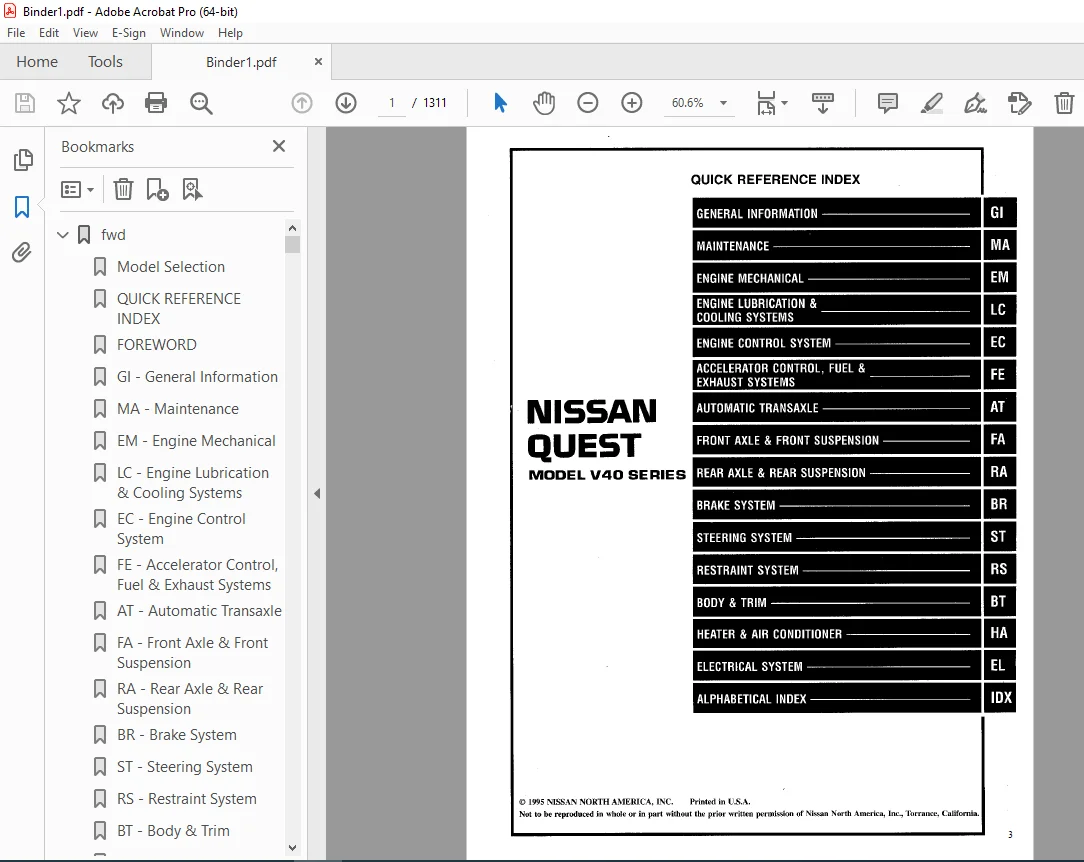
1996 NISSAN QUEST V40 Series Service Manual PDF DOWNLOAD
$24.95
1996 NISSAN QUEST V40 Series Service Manual PDF DOWNLOAD
Instant PDF Download
Available immediately
Save to Your Device
Download & keep forever
Antivirus Scanned
100% virus-free
Trusted Worldwide
175,000+ customers
Description
1996 NISSAN QUEST V40 Series Service Manual PDF DOWNLOAD
FILE DETAILS:
1996 NISSAN QUEST V40 Series Service Manual PDF DOWNLOAD
Language : English
Pages : 1311
Downloadable : Yes
File Type : PDF
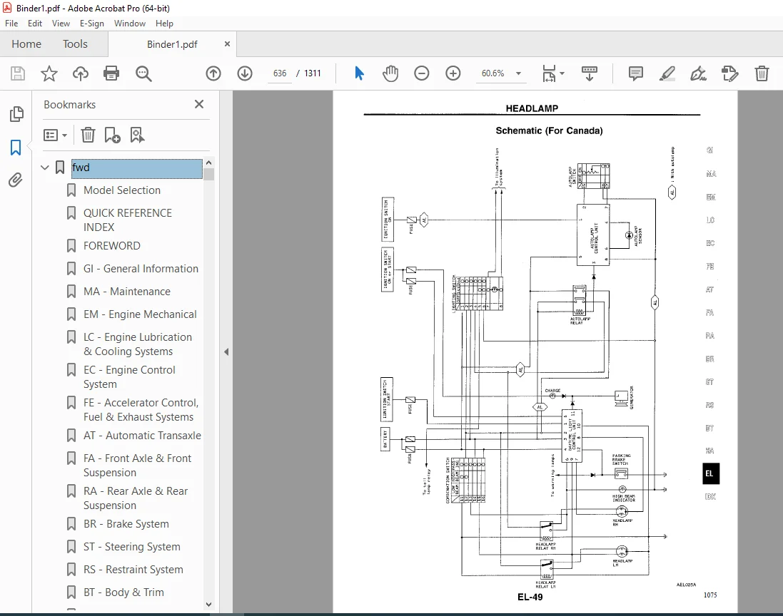
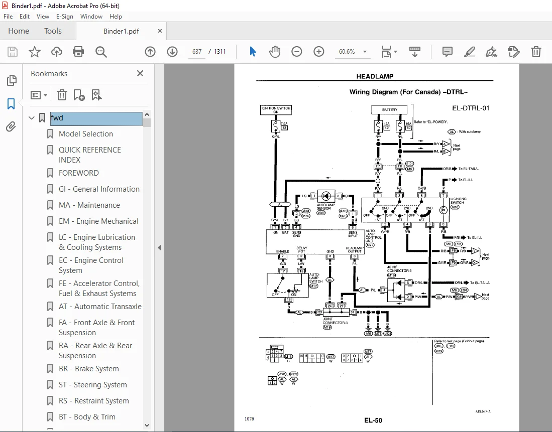
IMAGES PREVIEW OF THE MANUAL:
VIDEO PRVIEW:
https://vimeo.com/853309274?share=copy
TABLE OF CONTENTS:
1996 NISSAN QUEST V40 Series Service Manual PDF DOWNLOAD
fwd...........................................................................................................   1
	Model Selection...........................................................................................   0
	QUICK REFERENCE INDEX.....................................................................................   1
	FOREWORD..................................................................................................   2
	GI - General Information..................................................................................   0
	MA - Maintenance..........................................................................................   0
	EM - Engine Mechanical....................................................................................   0
	LC - Engine Lubrication & Cooling Systems.................................................................   0
	EC - Engine Control System................................................................................   0
	FE - Accelerator Control, Fuel & Exhaust Systems..........................................................   0
	AT - Automatic Transaxle..................................................................................   0
	FA - Front Axle & Front Suspension........................................................................   0
	RA - Rear Axle & Rear Suspension..........................................................................   0
	BR - Brake System.........................................................................................   0
	ST - Steering System......................................................................................   0
	RS - Restraint System.....................................................................................   0
	BT - Body & Trim..........................................................................................   0
	HA - Heater & Air Conditoner..............................................................................   0
	EL - Electrical System....................................................................................   0
	IDX - Alphabetical Index..................................................................................   1
	Foldout...................................................................................................   0
	Quick Reference Chart.....................................................................................   3
at............................................................................................................   4
	QUICK REFERENCE INDEX.....................................................................................   0
	TABLE OF CONTENTS.........................................................................................   4
	PREPARATION AND PRECAUTIONS...............................................................................   6
		Special Service Tools.................................................................................   6
		Commercial Service Tools..............................................................................   8
		Service Notice........................................................................................   9
		Precautions For Supplemental Restraint System (SRS) "AIR BAG".........................................  10
	DESCRIPTION...............................................................................................  11
		Cross-sectional View..................................................................................  11
		Hydraulic Control Circuit.............................................................................  12
		Shift Mechanism.......................................................................................  13
			Construction......................................................................................  13
			Function of Clutch And Brake......................................................................  13
			Operation of Clutch And Brake.....................................................................  14
		Control System........................................................................................  15
			A/T Control Unit Function.........................................................................  16
			Input/Output Signal of A/T Control Unit...........................................................  16
	TROUBLE DIAGNOSES.........................................................................................  17
		How to Perform Trouble Diagnoses for Quick and Accurate Repair........................................  17
		Remarks...............................................................................................  21
			Fail-Safe.........................................................................................  21
			ATF Cooler Service................................................................................  21
			OBD-II Self-Diagnosis.............................................................................  21
		Diagnostic Trouble Code (DTC) Chart...................................................................  22
		Diagnosis by CONSULT..................................................................................  24
		Preliminary Check.....................................................................................  28
			A/T Fluid Check...................................................................................  28
			Road Test.........................................................................................  28
			Shift Schedule....................................................................................  39
		A/T Electrical Parts Location.........................................................................  40
		Circuit Diagram for Quick Pinpoint Check..............................................................  41
		Wiring Diagram - AT -.................................................................................  42
		Self-diagnosis........................................................................................  48
			SELF-DIAGNOSTIC PROCEDURE (With CONSULT)..........................................................  48
			Judgement of Self-Diagnosis Code Indicated By OD OFF Indicator Lamp...............................  51
			HOW TO ERASE DTC (With CONSULT)...................................................................  53
			HOW TO ERASE DTC (With Generic Scan Tool (GST))...................................................  53
			HOW TO ERASE DTC (No Tools).......................................................................  53
			DTC P0720 Vehicle Speed Sensor-A/T (Revolution Sensor) Circuit Check..............................  54
			Vehicle Speed Sensor-MTR Circuit Check............................................................  56
			DTC P1705 Throttle Position Sensor Circuit Check..................................................  58
			DTC P0750 Shift Solenoid Valve A Circuit Check....................................................  60
			DTC P0755 Shift Solenoid Valve B Circuit Check....................................................  62
			DTC P1760 Overrun Clutch Solenoid Valve Circuit Check.............................................  64
			DTC P0740 Torque Converter Clutch Solenoid Valve Circuit Check....................................  66
			DTC P0710 A/T Fluid Temperature Sensor Circuit and A/T Control Unit Power Source Circuit Check....  68
			DTC P0725 Engine Speed Signal Circuit Check.......................................................  71
			DTC P0745 Line Pressure Solenoid Valve Circuit Check..............................................  73
			DTC P0705 Inhibitor, Overdrive and Throttle Position Switch Circuit Checks........................  75
			DTC P0731 Improper Shifting To 1st Gear Position..................................................  79
			DTC P0732 Improper Shifting To 2nd Gear Position..................................................  81
			DTC P0733 Improper Shifting To 3rd Gear Position..................................................  83
			DTC P0734 Improper Shifting To 4th Gear Position Or Improper Torque Converter Clutch Operation....  85
		Diagnostic Procedures.................................................................................  89
		Electrical Components Inspection...................................................................... 104
			Inspection of A/T Control Unit.................................................................... 104
			A/T Control Unit Inspection Table................................................................. 104
			Solenoid Valves and A/T Fluid Temperature Sensor.................................................. 108
			Overdrive Switch.................................................................................. 109
			Inhibitor Switch.................................................................................. 109
			Revolution Sensor................................................................................. 110
			Dropping Sensor................................................................................... 110
			Throttle Position Switch.......................................................................... 110
		Final Check........................................................................................... 111
			Stall Testing..................................................................................... 111
			Judgement of Stall Test........................................................................... 112
			Pressure Testing.................................................................................. 114
			Judgement of Line Pressure Test................................................................... 115
		Symptom Chart......................................................................................... 116
	TROUBLE DIAGNOSES - A/T Shift Lock System................................................................. 119
		Description........................................................................................... 119
		Shift Lock System Electrical Parts Location........................................................... 119
		Removal - Shift Lock Solenoid......................................................................... 119
		Wiring Diagram - SHIFT -.............................................................................. 120
		Diagnostic Procedure.................................................................................. 121
		Shift Lock Rod........................................................................................ 123
		Component Check....................................................................................... 124
	ON-VEHICLE SERVICE........................................................................................ 125
		Control Valve Assembly and Accumulator................................................................ 125
		Revolution Sensor Replacement......................................................................... 126
		Inhibitor Switch Adjustment........................................................................... 126
		Control Cable Adjustment.............................................................................. 127
		Position Indicator Adjustment......................................................................... 127
		Differential Side Oil Seal Replacement................................................................ 127
	REMOVAL AND INSTALLATION.................................................................................. 128
	MAJOR OVERHAUL............................................................................................ 130
		Oil Channel........................................................................................... 133
	DISASSEMBLY............................................................................................... 134
	REPAIR FOR COMPONENT PARTS................................................................................ 148
		Manual Shaft.......................................................................................... 148
		Oil Pump.............................................................................................. 150
		Control Valve Assembly................................................................................ 154
		Control Valve Upper Body.............................................................................. 162
		Control Valve Lower Body.............................................................................. 166
		Reverse Clutch........................................................................................ 168
		High Clutch........................................................................................... 171
		Forward Clutch and Overrun Clutch..................................................................... 175
		Low & Reverse Brake................................................................................... 181
		Rear Internal Gear, Forward Clutch Hub and Overrun Clutch Hub......................................... 184
		Output Shaft, Idler Gear, Reduction Pinion Gear and Bearing Retainer.................................. 188
		Band Servo Piston Assembly............................................................................ 193
		Final Drive........................................................................................... 198
	ASSEMBLY.................................................................................................. 202
		Assembly 1............................................................................................ 202
		Adjustment 1.......................................................................................... 202
			Differential Side Bearing Preload................................................................. 202
			Reduction Pinion Gear Bearing Preload............................................................. 204
			Output Shaft End Play............................................................................. 206
		Assembly 2............................................................................................ 207
		Adjustment 2.......................................................................................... 213
			Total End Play.................................................................................... 213
		Assembly 3............................................................................................ 215
	SERVICE DATA AND SPECIFICATIONS (SDS)..................................................................... 221
		General Specifications................................................................................ 221
		Specifications and Adjustments........................................................................ 221
			Vehicle Speed When Shifting Gears................................................................. 221
			Vehicle Speed When Performing Lock-up............................................................. 221
			Stall Revolution.................................................................................. 221
			Line Pressure..................................................................................... 221
			Control Valves.................................................................................... 222
			Clutches and Brakes............................................................................... 223
			Final Drive....................................................................................... 224
			Planetary Carrier and Oil Pump.................................................................... 225
			Input Shaft....................................................................................... 225
			Reduction Pinion Gear............................................................................. 225
			Reverse Clutch End Play........................................................................... 226
			Accumulator....................................................................................... 226
			Band Servo........................................................................................ 227
			Removal and Installation.......................................................................... 227
			Output Shaft...................................................................................... 227
			Bearing Retainer.................................................................................. 227
			Total End Play.................................................................................... 227
br............................................................................................................ 228
	QUICK REFERENCE INDEX.....................................................................................   0
	TABLE OF CONTENTS......................................................................................... 228
	PRECAUTIONS AND PREPARATION............................................................................... 229
		Precautions........................................................................................... 229
		Commercial Service Tools.............................................................................. 230
	CHECK AND ADJUSTMENT...................................................................................... 231
		Checking Brake Fluid Level............................................................................ 231
		Checking Brake Line................................................................................... 231
		Changing Brake Fluid.................................................................................. 231
	AIR BLEEDING.............................................................................................. 232
		Bleeding Procedure.................................................................................... 232
	BRAKE HYDRAULIC LINE...................................................................................... 233
	CONTROL VALVE............................................................................................. 235
		Dual Load Sensing Valve............................................................................... 235
	BRAKE PEDAL AND BRACKET................................................................................... 238
		Removal and Installation.............................................................................. 238
		Inspection............................................................................................ 238
		Adjustment............................................................................................ 239
	MASTER CYLINDER........................................................................................... 240
	BRAKE BOOSTER............................................................................................. 243
	VACUUM HOSE............................................................................................... 245
	FRONT DISC BRAKE.......................................................................................... 246
	REAR DRUM BRAKE........................................................................................... 250
	PARKING BRAKE CONTROL..................................................................................... 254
	ANTI-LOCK BRAKE SYSTEM.................................................................................... 256
		Purpose............................................................................................... 256
		Operation............................................................................................. 256
		System Components..................................................................................... 257
		System Description.................................................................................... 257
		Removal and Installation.............................................................................. 258
			Front Whel Sensor................................................................................. 258
			Rear Wheel Sensor................................................................................. 258
			ABS Actuator...................................................................................... 259
			Control Unit...................................................................................... 261
			ABS Control Actuator Relays....................................................................... 261
	TROUBLE DIAGNOSES......................................................................................... 262
		How to Perform Trouble Diagnoses for Quick and Accurate Repair........................................ 262
		Preliminary Check..................................................................................... 263
		Component Parts Location and Harness Layout........................................................... 264
		Circuit Diagram....................................................................................... 265
		Wiring Diagram - ABS -................................................................................ 266
		Self-diagnosis........................................................................................ 270
			Funtion........................................................................................... 270
			Self-Diagnosis Procedure.......................................................................... 270
			How To Read Self-Diagnostic Results (Malfunction codes)........................................... 271
			How To Erase Self-Diagnostic Results (Malfunction codes).......................................... 271
			Malfunction Code/Symptom Chart.................................................................... 272
		Ground Circuit Check.................................................................................. 273
		Diagnostic Procedures................................................................................. 274
		Electrical Components Inspection...................................................................... 290
	SERVICE DATA AND SPECIFICATIONS(SDS)...................................................................... 291
bt............................................................................................................ 292
	QUICK REFERENCE INDEX.....................................................................................   0
	TABLE OF CONTENTS......................................................................................... 292
	PRECAUTIONS............................................................................................... 293
		Supplemental Restraint System (SRS) "AIR BAG"......................................................... 293
	GENERAL SERVICING......................................................................................... 294
		Clip and Fastener..................................................................................... 294
	BODY END.................................................................................................. 297
		Body Front End........................................................................................ 297
			Removal - Front bumper assembly................................................................... 297
			Bumper Shock Absorber Inspection.................................................................. 300
		Body Rear End and Opener.............................................................................. 301
			Removal - Rear bumper assembly.................................................................... 301
			Bumper Shock Absorber Inspection - Rear........................................................... 301
	DOOR...................................................................................................... 304
		Front Door............................................................................................ 304
		Sliding Door.......................................................................................... 305
		Rear Door............................................................................................. 307
	INSTRUMENT PANEL.......................................................................................... 308
		Removal - Instrument panel assembly................................................................... 308
		Installation.......................................................................................... 308
	INTERIOR TRIM............................................................................................. 311
		Side and Floor Trim................................................................................... 311
		Roof Trim............................................................................................. 315
	EXTERIOR.................................................................................................. 317
		1. Hood front sealing rubber.......................................................................... 318
		2. 3. Hood rear sealing rubber & cowl top grille...................................................... 318
		4. Sun roof frame weatherstrip and sun roof lid weatherstrip.......................................... 318
		5. Windshield upper molding........................................................................... 318
		6. Windshield side molding............................................................................ 318
		7. Body side drip molding............................................................................. 319
		8. Waist rail finisher................................................................................ 319
		9. Front door weatherstrip............................................................................ 319
		10. Sliding door weatherstrip......................................................................... 319
		11. Sliding door lower seal........................................................................... 319
		12. Back door opening weatherstrip.................................................................... 319
		13. Luggage rack...................................................................................... 320
		14. Outside door molding.............................................................................. 321
		15. Front door corner covers.......................................................................... 322
		16. Side guard molding................................................................................ 322
	SEAT...................................................................................................... 323
		Front Seat............................................................................................ 323
		Front Power Seat...................................................................................... 324
		2nd Seat.............................................................................................. 325
			Type I............................................................................................ 325
			Type II........................................................................................... 326
		3rd Seat.............................................................................................. 327
			3rd Sliding Seat Rails- Installation.............................................................. 327
			Third Sliding Seat Rails.......................................................................... 328
	SUN ROOF.................................................................................................. 332
		Removal and Installation.............................................................................. 332
		Disassembly and Assembly - Guide rail assembly........................................................ 332
		Removal and Installation - Sun roof drain hoses....................................................... 332
	WINDSHIELD AND WINDOWS.................................................................................... 335
		Removal............................................................................................... 335
		Installation.......................................................................................... 335
		Windshield and Rear Window............................................................................ 336
			Repairing Water Leaks for Windshield.............................................................. 336
		Side Window (1st)..................................................................................... 337
		Side Window (2nd)..................................................................................... 338
			Installation...................................................................................... 338
	MIRROR.................................................................................................... 339
		Door Mirror........................................................................................... 339
		Rearview Mirror....................................................................................... 340
	BODY ALIGNMENT............................................................................................ 341
		Engine Compartment.................................................................................... 342
		Underbody............................................................................................. 344
ec............................................................................................................ 347
	QUICK REFERENCE INDEX.....................................................................................   0
	TABLE OF CONTENTS......................................................................................... 347
	PRECAUTIONS AND PREPARATION............................................................................... 349
		Special Service Tools................................................................................. 349
		Supplemental Restraint System (SRS) "AIR BAG"......................................................... 349
		Preautions for On Board Diagnostic (OBD) System of Engine and A/T..................................... 349
		Engine Fuel & Emission Control System................................................................. 350
		Precautions........................................................................................... 351
	ENGINE AND EMISSION CONTROL OVERALL SYSTEM................................................................ 353
		Circuit Diagram....................................................................................... 353
		System Diagram........................................................................................ 354
		ECCS Component Parts Location......................................................................... 355
		Vacuum Hose Drawing................................................................................... 357
		System Chart.......................................................................................... 358
	ENGINE AND EMISSION BASIC CONTROL SYSTEM DESCRIPTION...................................................... 359
		Multiport Fuel Injection (MFI) System................................................................. 359
		Distributor Ignition (DI) System...................................................................... 361
		Air Conditioning Cut Control.......................................................................... 362
		Fuel Cut Control...................................................................................... 363
	EVAPORATIVE EMISSION SYSTEM............................................................................... 364
	POSITIVE CRANKCASE VENTILATION............................................................................ 366
		PCV (Positive Crankcase Ventilation).................................................................. 366
	BASIC SERVICE PROCEDURE................................................................................... 367
		Fuel Pressure Release................................................................................. 367
		Fuel Pressure Check................................................................................... 367
		Fuel Pressure Regulator Check......................................................................... 368
		Injector Removal and Installation..................................................................... 368
		Fast Idle Cam (FIC) Inspection and Adjustment......................................................... 369
		Idle Speed/Ignition Timing/Idle Mixture Ratio Adjustment.............................................. 370
	ON BOARD DIAGNOSTIC SYSTEM DESCRIPTION.................................................................... 376
		Introduction.......................................................................................... 376
		Two Trip Detection Logic.............................................................................. 376
		Diagnostic Trouble Code (DTC)......................................................................... 376
		Freeze Frame Data..................................................................................... 377
		Malfunction Indicator Lamp (MIL)...................................................................... 378
		OBD System Operation Check............................................................................ 382
		CONSULT............................................................................................... 387
			CONSULT Inspection Procedure...................................................................... 387
			ECCS Component Parts/Control Systems Application.................................................. 388
			Function.......................................................................................... 389
			Work Support Mode................................................................................. 389
			Self-Diagnostic Mode.............................................................................. 390
			Data Monitor Mode................................................................................. 390
			Active Test Mode.................................................................................. 393
			Function Test Mode................................................................................ 394
			Freeze Frame Data................................................................................. 396
			Real Time Diagnosis In Data Monitor Mode.......................................................... 397
		Generic Scan Tool (GST)............................................................................... 398
	TROUBLE DIAGNOSIS - Introduction.......................................................................... 400
	TROUBLE DIAGNOSIS - Work Flow............................................................................. 402
	TROUBLE DIAGNOSIS - Basic Inspection...................................................................... 404
	TROUBLE DIAGNOSIS - Geneal Description.................................................................... 406
		Diagnostic Trouble Code (DTC) Chart................................................................... 406
		Fail-Safe Chart....................................................................................... 417
		Symptom Chart......................................................................................... 418
		CONSULT Reference Value in Data Monitor Mode.......................................................... 421
		Major Sensor Reference Graph in Data Monitor Mode..................................................... 423
		ECM Terminals and Reference Value..................................................................... 425
	TROUBLE DAIGNOSIS FOR POWER SUPPLY........................................................................ 431
		Main Power Supply and Ground Circuit.................................................................. 431
	DTC P0100, Mass Air Flow Sensor (MAFS) (DTC: 0102)........................................................ 434
	DTC P0110, Intake Air Temperature Sensor (DTC: 0401)...................................................... 439
	DTC P0115, Engine Temperature Sensor (ECTS) (DTC: 0103)................................................... 444
	DTC P0120, Throttle Position Sensor (DTC: 0403)........................................................... 448
	DTC P0125, Engine Coolant Temperature (ECT) Sensor (DTC: 0908)............................................ 453
	DTC P0130, Front Heated Oxygen Sensor (Front HO2S) (DTC: 0303)............................................ 458
	DTC P0130, Closed Loop Control (DTC: 0307)................................................................ 463
	DTC P0135, Front Heated Oxygen Sensor Heater (DTC: 0901).................................................. 464
	DTC P0136, Rear Heated Oxygen Sensor (Rear HO2S) (DTC: 0707).............................................. 467
	DTC P0141, Rear Heated Oxygen Sensor Heater (DTC: 0902)................................................... 472
	DTC P0171, Fuel Injection System Function (Lean side) (DTC:0115).......................................... 476
	DTC P0172, Fuel Injection System Function (Rich side) (DTC: 0114)......................................... 481
	DTC P0300 - P0306, No. 6 - 1 Cylinder Misfire, Multiple Cylinder Misfire (DTC: 0701 - 0603)............... 486
	DTC P0325, Knock Sensor (KS) (DTC:0304)................................................................... 490
	DTC P0335, Crankshaft Position Sensor (CKPS) (OBD) (DTC: 0802)............................................ 493
	DTC P0340, Camshaft Position Sensor (CMPS)(DTC: 0101)..................................................... 497
	DTC P0400, EGR Function (DTC: 0302)....................................................................... 502
	DTC P0402, EGRC-BPT Valve Function (DTC: 0306)............................................................ 510
	DTC P0420, Three Way Catalyst Function (DTC: 0702)........................................................ 512
	DTC P0500, Vehicle Speed Sensor (VSS) (DTC: 0104)......................................................... 515
	DTC P0505, Idle Air Control Valve (IACV) - Auxiliary Air Control (AAC) Valve (DTC: 0205).................. 519
	DTC P0600, A/T Control (DTC: 0504)........................................................................ 523
	DTC P0605, Engine Control Module (ECM)-ECCS Control Module (DTC: 0301).................................... 526
	DTC P0705, Park/Neutral Position Switch (DTC: 1003)....................................................... 528
	DTC P1320, Ignition Signal (DTC: 0201).................................................................... 531
	DTC P1336, Crankshaft Position Sensor (CKPS) (OBD) (COG) (DTC: 0905)...................................... 536
	DTC P1400, EGR Valve and EVAP Canister Purge Control Solenoid Valve (DTC: 1005)........................... 540
	DTC P1401, EGR Temperature Sensor (DTC: 0305)............................................................. 544
	DTC P1605, A/T Diagnosis Communication Line (DTC: 0804)................................................... 548
	DTC P1900, Cooling Fan (DTC: 1308)........................................................................ 551
	TROUBLE DIAGNOSIS FOR NON-DETECTABLE ITEMS................................................................ 562
		Injector.............................................................................................. 562
		Start Signal.......................................................................................... 565
		Fuel Pump............................................................................................. 567
		Power Steering Oil Pressure Switch.................................................................... 572
		IACV-FICD Solenoid Valve/Air Conditioning System Input................................................ 575
		Air Conditioner High Pressure Switch.................................................................. 580
		MIL & Data Link Connectors............................................................................ 582
	TROUBLE DIAGNOSIS - Index................................................................................. 583
		Alphabetical & P No. Index for DTC.................................................................... 583
	SERVICE DATA AND SPECIFICATIONS (SDS)..................................................................... 584
		General Specifications................................................................................ 584
		Inspection and Adjustment............................................................................. 584
el............................................................................................................ 586
	QUICK REFERENCE INDEX.....................................................................................   0
	TABLE OF CONTENTS......................................................................................... 586
	PRECAUTIONS............................................................................................... 589
		Supplemental Restraint System (SRS) "AIR BAG"......................................................... 589
	HARNESS CONNECTOR......................................................................................... 590
	STANDARDIZED RELAY........................................................................................ 591
	POWER SUPPLY ROUTING...................................................................................... 593
		Schematic............................................................................................. 593
		Wiring Diagram - POWER -.............................................................................. 595
		Fuse.................................................................................................. 603
		Fisible Link.......................................................................................... 603
		Circuit Breaker....................................................................................... 603
	GROUND DISTRIBUTION....................................................................................... 604
	BATTERY................................................................................................... 608
		How to Handle Battery................................................................................. 608
		Service Data and Specifications (SDS)................................................................. 611
	STARTING SYSTEM........................................................................................... 612
		System Description.................................................................................... 612
		Wiring Diagram - START -.............................................................................. 613
		Starter............................................................................................... 615
		Removal and Installation.............................................................................. 616
		Pinion/Clutch Check................................................................................... 616
		Service Data and Specifications (SDS)................................................................. 616
	CHARGING SYSTEM........................................................................................... 617
		System Description.................................................................................... 617
		Wiring Diagram - CHARGE -............................................................................. 618
		Trouble Diagnoses..................................................................................... 619
	CHARGING SYSTEM - Generator............................................................................... 620
		Construction.......................................................................................... 620
		Removal and Installation.............................................................................. 620
		Diode Check........................................................................................... 621
		Assembly.............................................................................................. 621
		Service Data and Specifications (SDS)................................................................. 622
	COMBINATION SWITCH........................................................................................ 623
		Combination Switch/Check.............................................................................. 623
		Combination Switch/Replacement........................................................................ 624
		Steering Switch/Check................................................................................. 625
	HEADLAMP.................................................................................................. 626
		System Description (For USA).......................................................................... 626
		Schematic (For USA)................................................................................... 627
		Wiring Diagram (For USA) - H/LAMP -................................................................... 629
		Trouble Diagnoses (For USA)........................................................................... 631
		System Description (For Canada)....................................................................... 633
		Operation (Daytime light system for Canada)........................................................... 635
		Schematic (For Canada)................................................................................ 636
		Wiring Diagram (For Canada) -DTRL -................................................................... 637
		Trouble Diagnoses (For Canada)........................................................................ 640
		Bulb Replacement...................................................................................... 642
		Aiming Adjustment..................................................................................... 642
	AUTOLAMP.................................................................................................. 644
		System Description.................................................................................... 644
		Trouble Diagnoses..................................................................................... 645
	EXTERIOR LAMP............................................................................................. 649
		Back-up Lamp/Wiring Diagram - BACK/L -................................................................ 649
		Clearance, License, Tail and Stop Lamps/Wiring Diagram - TAIL/L -..................................... 651
		Turn Signal and Hazard Warning Lamps/System Description............................................... 653
		Turn Signal and Hazard Warning Lamps/Wiring Diagram - TURN -.......................................... 655
		Turn Signal and Hazard Warning Lamps/Trouble Diagnoses................................................ 657
		Cornering Lamp/System Description..................................................................... 658
		Cornering Lamp/Wiring Diagram - CORNER -.............................................................. 659
		Combination Flasher Unit Check........................................................................ 660
		Bulb Specifications................................................................................... 660
	TRAILER TOW............................................................................................... 661
		System Description.................................................................................... 661
		Wiring Diagram - T/TOW -.............................................................................. 662
		Trouble Diagnoses..................................................................................... 663
	INTERIOR LAMP............................................................................................. 664
		Illumination/System Description....................................................................... 664
		Illumination/Schematic................................................................................ 666
		Illumination/Wiring Diagram - ILL -................................................................... 667
		Interior, MAP, Personal, Step and Tailgate Lamps/System Description................................... 671
		Interior, MAP, Personal, Step and Tailgate Lamps/Schematic............................................ 674
		Interior, MAP, Personal, Step and Tailgate Lamps/Wiring Diagram - INT/L -............................. 675
		Bulb Specifications................................................................................... 678
	METERS AND GAUGES......................................................................................... 679
		System Description.................................................................................... 679
		Combination Meter..................................................................................... 680
		Speedometer, Tachometer, Temp. and Fuel Gauges/Wiring Diagram - METER -............................... 681
		Inspection/Water Temperature Gauge.................................................................... 682
		Injection/Fuel Gauge.................................................................................. 683
		Inspection/Tachometer................................................................................. 684
		Inspection/Speedometer and Vehicle Speed Sensor....................................................... 685
		Injection/Speedometer and Fuse........................................................................ 686
		Fuel Tank Gauge Unit Check............................................................................ 687
		Thermal Transmitter Check............................................................................. 687
		Vehicle Speed Sensor Signal Check..................................................................... 687
	WARNING LAMPS AND CHIMES.................................................................................. 688
		Warning Lamps/System Description...................................................................... 688
		Warning Lamps/Schematic............................................................................... 690
		Warning Lamps/Wiring Diagram - WARN -................................................................. 691
		Low Fuel Level Warning Lamp........................................................................... 695
		Oil Pressure Switch Check............................................................................. 695
		Diode Check........................................................................................... 695
		Warning Chime/System Description...................................................................... 696
		Warning Chime/Wiring Diagram - CHIME -................................................................ 697
		Warning Chime/Trouble Diagnoses....................................................................... 698
		Diode Check........................................................................................... 704
		Warning Chime Check................................................................................... 704
	WIPER AND WASHER.......................................................................................... 705
		Front Wiper and Washer/System Description............................................................. 705
		Front Wiper and Washer/Wiring Diagram - WIPER -....................................................... 706
		Front Wiper and Washer/Trouble Diagnoses.............................................................. 707
		Front Wiper........................................................................................... 709
			Removal........................................................................................... 709
			Installation...................................................................................... 709
			Wiper Arm Adjustment.............................................................................. 709
			Washer Nozzle Adjustment.......................................................................... 709
		Rear Wiper and Washer (With Normal Glass)/System Description.......................................... 710
		Rear wiper and Washer (Except for Glass Hatch Model)/Wiring Diagram - WIP/R -......................... 711
		Rear Wiper and Washer (With Glass Hatch Model)/System Description..................................... 712
		Rear Wiper and Washer (For Glass Hatch Model/Wiring Diagram - WIP/HR -................................ 713
		Rear Wiper............................................................................................ 714
		Washer Fluid and Check Valve.......................................................................... 715
	POWER WINDOW.............................................................................................. 716
		Component Layout...................................................................................... 716
		System Description.................................................................................... 717
		Wiring Diagram - WINDOW -............................................................................. 721
		Trouble Diagnoses..................................................................................... 723
	POWER DOOR LOCK........................................................................................... 724
		System Description.................................................................................... 724
		Schematic............................................................................................. 727
		Wiring Diagram - D/LOCK -............................................................................. 729
		Trouble Diagnoses..................................................................................... 733
			Diagnostic Procedures............................................................................. 735
	POWER DOOR MIRROR......................................................................................... 740
	HEATED MIRROR............................................................................................. 741
	POWER SEAT................................................................................................ 743
	ELECTRIC SUNROOF.......................................................................................... 745
	HORN AND LIGHTER.......................................................................................... 747
	REAR WINDOW DEFOGGER...................................................................................... 748
		System Description.................................................................................... 748
		Wiring Diagram - DEF -................................................................................ 749
		Trouble Diagnoses..................................................................................... 750
		Filament Check........................................................................................ 751
		Filament Repair....................................................................................... 752
	AUDIO AND POWER ANTENNA................................................................................... 754
		Audio/System Description.............................................................................. 754
		Audio/Schematic....................................................................................... 755
		Audio/Wiring  Diagram - AUDIO -....................................................................... 757
		Power Antenna/System Description...................................................................... 761
		Power Antenna/Wiring Diagram - P/ANT -................................................................ 762
		Trouble Diagnoses..................................................................................... 763
		Location of Antenna................................................................................... 767
		Antenna Rod Replacement............................................................................... 767
	MULTI-REMOTE CONTROL SYSTEM............................................................................... 769
		System Description.................................................................................... 769
		Schematic............................................................................................. 772
		Wiring Diagram - MULTI -.............................................................................. 773
		Input/Output Operational Signal....................................................................... 777
		Trouble Diagnoses..................................................................................... 779
		Replacing Remote Controller or Multi-Remote Control Unit.............................................. 785
	AUTOMATIC SPEED CONTROL DEVICE (ASCD)..................................................................... 786
		Component Parts and Harness Connector Location........................................................ 786
		System Description.................................................................................... 787
		Schematic............................................................................................. 789
		Wiring Diagram - ASCD -............................................................................... 790
		Trouble Diagnoses..................................................................................... 795
			Fail-Safe System.................................................................................. 795
			Symptom Chart..................................................................................... 797
			Diagnostic Procedures............................................................................. 798
			ASCD Wire Adjustment.............................................................................. 805
			Electrical Components Inspection.................................................................. 806
	THEFT WARNING SYSTEM...................................................................................... 808
		Component Parts and Harness Connector Location........................................................ 808
		System Description.................................................................................... 810
		Schematic............................................................................................. 814
		Wiring Diagram - THEFT -.............................................................................. 815
		Trouble Diagnoses..................................................................................... 824
	LOCATION OF ELECTRICAL UNITS.............................................................................. 845
		Engine Compartment.................................................................................... 845
		Passenger Compartment................................................................................. 846
		Luggage Compartment................................................................................... 847
	HARNESS LAYOUT............................................................................................ 848
		How To Read Harness Layout............................................................................ 848
		Outline............................................................................................... 849
		Main Harness.......................................................................................... 850
		Body Harness.......................................................................................... 854
		Engine Control Harness................................................................................ 856
		Engine Control Sub-Harness............................................................................ 859
		Engine Room Harness................................................................................... 860
		A/T Control Harness................................................................................... 863
		Room Lamp Harness..................................................................................... 864
		Air Bag Harness....................................................................................... 865
		Front Door Harness.................................................................................... 866
		Back Door Harness..................................................................................... 867
		Sliding Door Harness.................................................................................. 868
	SUPER MULTIPLE JUNCTION (SMJ).............................................................................   0
	JOINT CONNECTOR (J/C).....................................................................................   2
	FUSE BLOCK/FUSE AND FUSIBLE LINK BOX......................................................................   3
	CONTROL UNITS.............................................................................................   4
em............................................................................................................ 869
	QUICK REFERENCE INDEX.....................................................................................   0
	TABLE OF CONTENTS......................................................................................... 869
	PRECAUTIONS............................................................................................... 870
		Parts Requiring Angular Tightening.................................................................... 870
		Liquid Gasket Application Procedure................................................................... 870
	PREPARATION............................................................................................... 871
		Special Service Tools................................................................................. 871
		Commercial Service Tools.............................................................................. 872
	OUTER COMPONENT PARTS..................................................................................... 873
	COMPRESSION PRESSURE...................................................................................... 875
		Measurement of Compression Pressure................................................................... 875
	OIL PAN................................................................................................... 876
		Removal............................................................................................... 876
		Installation.......................................................................................... 877
	TIMING BELT............................................................................................... 879
		Removal............................................................................................... 880
		Inspection............................................................................................ 882
		Installation.......................................................................................... 883
	OIL SEAL REPLACEMENT...................................................................................... 886
	CYLINDER HEAD............................................................................................. 888
		Removal............................................................................................... 889
		Disassembly........................................................................................... 892
		Inspection............................................................................................ 893
		Assembly.............................................................................................. 900
		Installation.......................................................................................... 901
	ENGINE REMOVAL............................................................................................ 905
		Removal............................................................................................... 906
		Installation.......................................................................................... 907
	CYLINDER BLOCK............................................................................................ 908
		Disassembly........................................................................................... 909
		Inspection............................................................................................ 909
		Assembly.............................................................................................. 916
	SERVICE DATA AND SPECIFICATIONS (SDS)..................................................................... 919
		General Specifications................................................................................ 919
		Inspection and Adjustment............................................................................. 919
fa............................................................................................................ 926
	QUICK REFERENCE INDEX.....................................................................................   0
	TABLE OF CONTENTS......................................................................................... 926
	PRECAUTIONS AND PREPARATION............................................................................... 927
		Precautions........................................................................................... 927
		Special Service Tools................................................................................. 927
		Commercial Service Tools.............................................................................. 928
	FRONT AXLE AND FRONT SUSPENSION........................................................................... 929
	ON-VEHICLE SERVICE........................................................................................ 930
		Front Axle and Front Suspension Parts................................................................. 930
		Front Wheel Bearing................................................................................... 931
		Front Wheel Alignment................................................................................. 931
		Drive Shaft........................................................................................... 933
	FRONT AXLE................................................................................................ 934
		Wheel Hub Knuckle..................................................................................... 935
		Drive Shaft........................................................................................... 938
	FRONT SUSPENSION.......................................................................................... 946
		Coil Spring and Strut Assembly........................................................................ 947
		Stabilizer Bar........................................................................................ 948
		Transverse Link and Transverse Link Gusset............................................................ 949
		Lower Ball Joint...................................................................................... 949
	SERVICE DATA AND SPECIFICATIONS (SDS)..................................................................... 951
		General Specifications................................................................................ 951
		Inspection and Adjustment............................................................................. 952
fe............................................................................................................ 953
	QUICK REFERENCE INDEX.....................................................................................   0
	TABLE OF CONTENTS......................................................................................... 953
	ACCELERATOR CONTROL SYSTEM................................................................................ 954
		Adjusting Accelerator Wire............................................................................ 954
	FUEL SYSTEM............................................................................................... 955
		Fuel Tank............................................................................................. 955
			Removal........................................................................................... 956
			Installation...................................................................................... 957
		Fuel Pump and Guage................................................................................... 957
			Removal........................................................................................... 957
			Installation...................................................................................... 957
	EXHAUST SYSTEM............................................................................................ 958
		Arrangement........................................................................................... 959
foldout....................................................................................................... 960
	QUICK REFERENCE INDEX.....................................................................................   0
	ELECTRICAL SYSTEM.........................................................................................   2
	SUPER MULTIPLE JUNCTION (SMJ)............................................................................. 960
		Terminal Arrangement.................................................................................. 961
	JOINT CONNECTOR (J/C)..................................................................................... 962
	FUSE BLOCK/FUSE AND FUSIBLE LINK BOX...................................................................... 963
	CONTROL UNITS............................................................................................. 964
gi............................................................................................................ 965
	QUICK REFERENCE INDEX.....................................................................................   0
	TABLE OF CONTENTS......................................................................................... 965
	PREAUTIONS................................................................................................ 966
		Precautions for Supplemental Restraint Tystem (SRS) "AIR BAG"......................................... 966
		General Precautions................................................................................... 966
		Precautions for Multiport Fuel Injection System....................................................... 968
		Precautions for Three Way Catalyst.................................................................... 968
		Engine Oils........................................................................................... 968
		Precautions for Fuel.................................................................................. 969
		Precautions for Air Conditioning...................................................................... 969
	HOW TO USE THIS MANUAL.................................................................................... 970
	HOW TO READ WIRING DIAGRAMS............................................................................... 972
		Sample/Wiring Diagram - EXAMPL -...................................................................... 972
		Description........................................................................................... 974
		Wiring Diagram Codes (Cell Codes)..................................................................... 980
	HOW TO PERFORM EFFICIENT DIAGNOSIS FOR AN ELECTRICAL INCIDENT............................................. 981
		Work Flow............................................................................................. 981
		Incident Simulation Tests............................................................................. 982
		Circuit Inspection.................................................................................... 986
	HOW TO FOLLOW FLOW CHART IN TROUBLE DIAGNOSES............................................................. 992
		Notice................................................................................................ 992
		How To Follow This Flowchart.......................................................................... 993
	CONSULT CHECKING SYSTEM................................................................................... 996
		Function and System Application....................................................................... 996
		Lithium Battery Replacement........................................................................... 996
		Checking Equipment.................................................................................... 996
	IDENTIFICATION INFORMATION................................................................................ 997
		Model Variation....................................................................................... 997
		Identification Number................................................................................. 998
		Dimensions............................................................................................ 999
		Wheels and Tires...................................................................................... 999
	LIFTING POINTS AND TOW TRUCK TOWING.......................................................................1000
		Preparation...........................................................................................1000
		Board-on Lift.........................................................................................1000
		Garage Jack and Safety Stand..........................................................................1001
		2-pole Lift...........................................................................................1001
		Tow Truck Towing......................................................................................1002
	TIGHTENING TORQUE OF STANDARD BOLTS.......................................................................1003
	SAE J1930 TERMINOLOGY LIST................................................................................1004
ha............................................................................................................1008
	QUICK REFERENCE INDEX.....................................................................................   0
	TABLE OF CONTENTS.........................................................................................1008
	MANUAL AND AUTO...........................................................................................1010
		PRECAUTIONS AND PREPARATION...........................................................................1010
			Precautions for Supplemental Restraint Sytem (SRS) "AIR BAG"......................................1010
			Identification....................................................................................1010
			Precautions for Working with R-134a...............................................................1011
			Precautions for Working with Refrigerants.........................................................1011
			Precautions for Refrigerant Connections...........................................................1012
			Precautions for Servicing Compressor..............................................................1013
			R-134a Service Tools and Equipment................................................................1014
			Commercial Service Tools..........................................................................1016
			Precautions for Service Equipment.................................................................1018
		DESCRIPTION...........................................................................................1020
			Refrigeration Cycle...............................................................................1020
			Component Layout..................................................................................1022
	MANUAL....................................................................................................1023
		DESCRIPTION...........................................................................................1023
			Control Operation.................................................................................1023
			Discharge Air Flow................................................................................1024
		TROUBLE DIAGNOSES.....................................................................................1026
			How to Perform Trouble Diagnoses for Quick and Accurate Repair....................................1026
			Operational Check.................................................................................1027
			Symptom Chart.....................................................................................1030
			Preliminary Check.................................................................................1031
			Performance Test Diagnoses........................................................................1038
			Harness Layout....................................................................................1041
			Circuit Diagram...................................................................................1044
			Wiring Diagram - A/C, M -.........................................................................1045
			Main Power Supply and Ground Circuit Check........................................................1050
			Diagnostic Procedures.............................................................................1052
			Electrical Components Inspection..................................................................1071
			Control Linkage Adjustment........................................................................1073
	AUTO......................................................................................................1076
		DESCRIPTION...........................................................................................1076
			Introduction......................................................................................1076
			Features..........................................................................................1076
			Control Operation.................................................................................1077
			Discharge Air Flow................................................................................1079
		TROUBLE DIAGNOSES.....................................................................................1081
			How to Perform Trouble Diagnoses for Quick and Accurate Repair....................................1081
			Operational Check.................................................................................1082
			Symptom Chart.....................................................................................1085
			Self-diagnosis....................................................................................1086
			Preliminary Check.................................................................................1088
			Performance Test Diagnoses........................................................................1095
			Harness Layout....................................................................................1098
			Circuit Diagram...................................................................................1102
			Wiring Diagram - A/C, A -.........................................................................1103
			Main Power Supply and Ground Circuit Check........................................................1108
			Diagnostic Procedures.............................................................................1110
			Electrical Components Inspection..................................................................1138
			Control Linkage Adjustment........................................................................1140
		SYSTEM DESCRIPTION....................................................................................1142
			Overview of Control System........................................................................1142
			Control System Input Components...................................................................1143
			Control System Electronic Automatic Temperature Control Unit (EATC Unit)..........................1145
			Control System Output Components..................................................................1146
	MANUAL AND AUTO...........................................................................................1155
		SERVICE PROCEDURES....................................................................................1155
			Checking Refrigerant Leaks........................................................................1155
			R-134a Service Procedure..........................................................................1157
			Compressor Lubricant Quantity.....................................................................1159
			Refrigerant Lines.................................................................................1161
			Compressor (Ford Model FS-10).....................................................................1163
			Clutch Hub and Pulley.............................................................................1164
			Magnet Clutch Coil................................................................................1166
			Shaft Seal........................................................................................1167
			Belt Tension......................................................................................1169
			Fast Idle Control Device (FICD)...................................................................1169
			Front Heater Core.................................................................................1169
			Front Evaporator Core.............................................................................1171
			Rear Heater Core and Evaporator Core..............................................................1172
			Fan Switch and Illumination Bulbs.................................................................1173
			Spring Lock Coupling..............................................................................1175
		SERVICE DATA AND SPECIFICATIONS (SDS).................................................................1177
			General Specifications............................................................................1177
			Inspection and Adjustment.........................................................................1177
idx...........................................................................................................1178
	QUICK REFERENCE INDEX.....................................................................................   0
lc............................................................................................................1186
	QUICK REFERENCE INDEX.....................................................................................   0
	TABLE OF CONTENTS.........................................................................................1186
	PRECAUTIONS...............................................................................................1187
		Supplemental Restraint System (SRS) "AIR BAG".........................................................1187
		Liquid Gasket Application Procedure...................................................................1187
	PREPARATION...............................................................................................1188
		Special Service Tools.................................................................................1188
	ENGINE LUBRICATION SYSTEM.................................................................................1189
		Lubrication Circuit...................................................................................1189
		Oil Pressure Check....................................................................................1190
		Oil Pump..............................................................................................1190
	ENGINE COOLING SYSTEM.....................................................................................1194
		Cooling Circuit.......................................................................................1194
		System Check..........................................................................................1194
		Water Pump............................................................................................1196
		Thermostat............................................................................................1198
		Radiator..............................................................................................1200
		Cooling Fan Control System............................................................................1201
	SERVICE DATA AND SPECIFICATIONS (SDS).....................................................................1202
		Engine Lubrication System.............................................................................1202
		Engine Cooling System.................................................................................1202
ma............................................................................................................1203
	QUICK REFERENCE INDEX.....................................................................................   0
	TABLE OF CONTENTS.........................................................................................1203
	PRECAUTIONS AND PREPARATION...............................................................................1204
		Supplemental Restraint System (SRS) "AIR BAG".........................................................1204
	GENERAL MAINTENANCE.......................................................................................1205
	PERIODIC MAINTENANCE......................................................................................1207
		Schedule 1............................................................................................1208
		Schedule 2............................................................................................1209
	RECOMMENDED FLUIDS AND LUBRICANTS.........................................................................1210
		Fluid and Lubricants..................................................................................1210
		SAE Viscosity Number..................................................................................1211
		Antifreeze Coolant Mixture Ratio......................................................................1211
	ENGINE MAINTENANCE........................................................................................1212
		Checking Drive Belts..................................................................................1212
		Changing Engine Coolant...............................................................................1213
		Checking Fuel Lines...................................................................................1218
		Changing Fuel Filter..................................................................................1218
		Changing Air Cleaner Filter...........................................................................1219
		Changing Engine Oil...................................................................................1219
		Changing Oil Filter...................................................................................1220
		Changing Spark Plugs..................................................................................1221
		Checking EVAP Vapor & Purge Lines.....................................................................1221
	CHASSIS AND BODY MAINTENANCE..............................................................................1222
		Checking Exhaust System...............................................................................1222
		Checking A/T Fluid....................................................................................1222
		Changing A/T Fluid....................................................................................1223
		Checking Brake Fluid Level and Leaks..................................................................1223
		Checking Brake Lines and Cables.......................................................................1223
		Checking Disc Brake...................................................................................1223
		Checking Drum Brake...................................................................................1224
		Balancing Wheels......................................................................................1225
		Tire Rotation.........................................................................................1225
		Checking Steering Gear and Linkage....................................................................1225
		Checking Power Steering Fluid and Lines...............................................................1225
		Lubricating Hood Latches, Locks, Hinges, Sliding Door Rollers and Links...............................1226
		Checking Seat Belts, Buckles, Retractors, Anchors and Adjusters.......................................1227
	SERVICE DATA AND SPECIFICATIONS (SDS).....................................................................1228
		Engine Maintenance....................................................................................1228
		Chassis and Body Maintenance..........................................................................1229
ra............................................................................................................1230
	QUICK REFERENCE INDEX.....................................................................................   0
	TABLE OF CONTENTS.........................................................................................1230
	PRECAUTIONS AND PREPARATION...............................................................................1231
		Precautions...........................................................................................1231
		Commercial Service Tools..............................................................................1231
	REAR SUSPENSION SYSTEM....................................................................................1232
	ON-VEHICLE SERVICE........................................................................................1233
		Rear Axle and Rear Suspension Parts...................................................................1233
		Rear Wheel Bearing....................................................................................1233
		Rear Wheel Alignment..................................................................................1234
	REAR AXLE.................................................................................................1235
		Wheel Hub.............................................................................................1235
	REAR SUSPENSION AND AXLE..................................................................................1238
		Removal and Installation..............................................................................1238
	REAR SUSPENSION...........................................................................................1240
		Leaf Spring...........................................................................................1240
		Shock Absorber........................................................................................1242
		Stabilizer Bar........................................................................................1242
	SERVICE DATA AND SPECIFICATIONS (SDS).....................................................................1244
		General Specifications................................................................................1244
		Inspection and Adjustment.............................................................................1244
rs............................................................................................................1245
	QUICK REFERENCE INDEX.....................................................................................   0
	TABLE OF CONTENTS.........................................................................................1245
	PRECAUTION................................................................................................1246
		Supplemental Restraint System (SRS) "AIR BAG".........................................................1246
	SEAT BELTS................................................................................................1247
		Front Seat Belt.......................................................................................1248
		Rear Seat Belts.......................................................................................1250
		Built-in Child Seat...................................................................................1252
	SUPPLEMENTAL RESTRAINT SYSTEM (SRS).......................................................................1254
		Precautions for SRS "Air Bag" Service.................................................................1254
		Special Service Tools.................................................................................1254
		Description...........................................................................................1255
		SRS component Parts Location..........................................................................1255
		Maintenance Items.....................................................................................1256
		Removal and Installation - Diagnosis Sensor Unit......................................................1257
		Removal - Air Bag Module and Spiral Cable.............................................................1258
		Installation - Air Bag Module and Spiral Cable........................................................1259
		Removal - Front Passenger Air Bag Module..............................................................1260
		Installation - Front Passenger Air Bag Module.........................................................1261
		Disposal of Air Bag Module............................................................................1262
	TROUBLE DIAGNOSES - Supplemental Restraint System (SRS)...................................................1266
		How to Perform Trouble Diagnoses for Quick and Accurate Repair........................................1266
		Schematic.............................................................................................1268
		Wiring Diagram - SRS -................................................................................1269
		Self-diagnosis........................................................................................1271
			Diagnostic Procedures.............................................................................1271
		Trouble Diagnoses for Air Bag Warning Lamp............................................................1285
	COLLISION DIAGNOSIS.......................................................................................1287
st............................................................................................................1288
	QUICK REFERENCE INDEX.....................................................................................   0
	TABLE OF CONTENTS.........................................................................................1288
	PRECAUTIONS AND PREPARATION...............................................................................1289
		Supplemental Restraint System (SRS) "AIR BAG".........................................................1289
			Steering System...................................................................................1289
		Special Service Tools.................................................................................1289
		Commercial Service Tool...............................................................................1291
	ON-VEHICLE SERVICE........................................................................................1292
		Checking and Adjusting Drive Belts....................................................................1292
		Checking Fluid Level..................................................................................1292
		Checking Fluid Leakage................................................................................1292
		Bleeding Hydraulic System.............................................................................1292
		Checking Steering Wheel Turning Force (For power steering)............................................1293
		Checking Steering Wheel Play..........................................................................1293
		Checking Neutral Position on Stering Wheel............................................................1294
		Front Wheel Turning Angle.............................................................................1294
		Checking Gear Housing Movement........................................................................1294
		Checking Hydraulic System.............................................................................1294
	STEERING WHEEL AND STEERING COLUMN........................................................................1296
		Removal...............................................................................................1296
		Installation..........................................................................................1297
		Disassembly and Assembly..............................................................................1298
		Inspection............................................................................................1300
	POWER STEERING GEAR AND LINKAGE...........................................................................1301
		Removal and Installation..............................................................................1301
		Description...........................................................................................1303
		Disassembly...........................................................................................1304
		Inspection............................................................................................1304
		Assembly..............................................................................................1305
	POWER STEERING OIL PUMP...................................................................................1307
		Pre-disassembly Inspection............................................................................1307
		Inspection............................................................................................1308
		Disassembly...........................................................................................1308
		Assembly..............................................................................................1308
	SERVICE DATA AND SPECIFICATIONS (SDS).....................................................................1310
		General Specifications................................................................................1310
		Inspection and Adjustment.............................................................................1310
DESCRIPTION:
1996 NISSAN QUEST V40 Series Service Manual PDF DOWNLOAD
FOREWORD
- This manual contains maintenance and repair procedures for the 1996 Nissan QUEST.
- In order to assure your safety and the efficient functioning of the vehicle, this manual should be read thoroughly.
- It is especially important that the PRECAUTIONS in the GI section be completely understood before starting any repair task.
- All information in this manual is based on the latest product information at the time of publication. The right is reserved to make changes in specifications and methods at any time without notice
PLEASE NOTE:
- This is the same manual used by the dealers to diagnose and troubleshoot your vehicle
- You will be directed to the download page as soon as the purchase is completed. The whole payment and downloading process will take anywhere between 2-5 minutes
- Need any other service / repair / parts manual, please feel free to contact [email protected] . We still have 50,000 manuals unlisted
G.P