Trusted Business
Verified & Licensed
Virus Free Files
100% Safe Downloads
Secure Payment
SSL Protected
Instant Delivery
Available Immediately
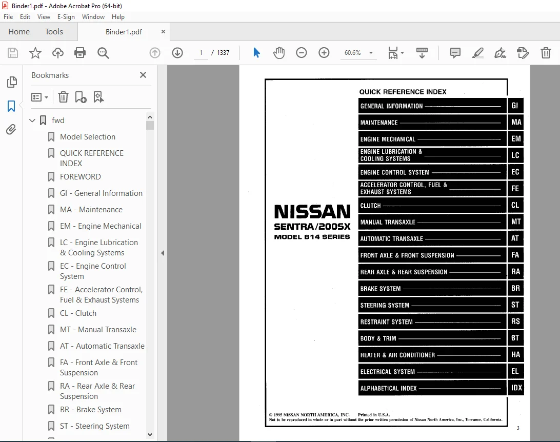
1996 NISSAN SENTRA 200SX B14 Series Service Manual PDF DOWNLOAD
$24.95
1996 NISSAN SENTRA 200SX B14 Series Service Manual PDF DOWNLOAD
Instant PDF Download
Available immediately
Save to Your Device
Download & keep forever
Antivirus Scanned
100% virus-free
Trusted Worldwide
175,000+ customers
Description
1996 NISSAN SENTRA 200SX B14 Series Service Manual PDF DOWNLOAD
FILE DETAILS:
1996 NISSAN SENTRA 200SX B14 Series Service Manual PDF DOWNLOAD
Language : English
Pages : 1337
Downloadable : Yes
File Type : PDF
IMAGES PREVIEW OF THE MANUAL:
VIDEO PRVIEW:
https://vimeo.com/853251314?share=copy
TABLE OF CONTENTS:
1996 NISSAN SENTRA 200SX B14 Series Service Manual PDF DOWNLOAD
fwd....................................................................................................   1
	Model Selection....................................................................................   0
	QUICK REFERENCE INDEX..............................................................................   1
	FOREWORD...........................................................................................   2
	GI - General Information...........................................................................   0
	MA - Maintenance...................................................................................   0
	EM - Engine Mechanical.............................................................................   0
	LC - Engine Lubrication & Cooling Systems..........................................................   0
	EC - Engine Control System.........................................................................   0
	FE - Accelerator Control, Fuel & Exhaust Systems...................................................   0
	CL - Clutch........................................................................................   0
	MT - Manual Transaxle..............................................................................   0
	AT - Automatic Transaxle...........................................................................   0
	FA - Front Axle & Front Suspension.................................................................   0
	RA - Rear Axle & Rear Suspension...................................................................   0
	BR - Brake System..................................................................................   0
	ST - Steering System...............................................................................   0
	RS - Restraint System..............................................................................   0
	BT - Body & Trim...................................................................................   0
	HA - Heater & Air Conditioner......................................................................   0
	EL - Electrical System.............................................................................   0
	IDX - Alphabetical Index...........................................................................   1
	Foldout............................................................................................   0
	Quick Reference Chart..............................................................................   3
BR.....................................................................................................   4
	QUICK REFERENCE INDEX..............................................................................   0
	TABLE OF CONTENTS..................................................................................   4
	PRECAUTIONS AND PREPARATION........................................................................   5
		Precautions....................................................................................   5
			Supplemental Restraint System (SRS) "Air Bag"..............................................   5
			Brake System...............................................................................   5
		Commercial Service Tools.......................................................................   6
	CHECK AND ADJUSTMENT...............................................................................   7
		Checking Brake Fluid Level.....................................................................   7
		Checking Brake Line............................................................................   7
		Changing Brake Fluid...........................................................................   7
	AIR BLEEDING.......................................................................................   8
		Bleeding Procedure.............................................................................   8
	BRAKE HYDRAULIC LINE...............................................................................   9
	CONTROL VALVE......................................................................................  11
		Proportioning Valve............................................................................  11
	BRAKE PEDAL AND BRACKET............................................................................  13
	MASTER CYLINDER....................................................................................  14
	BRAKE BOOSTER......................................................................................  17
	VACUUM HOSE........................................................................................  19
	FRONT DISC BRAKE...................................................................................  20
	REAR DRUM BRAKE....................................................................................  24
	REAR DISC BRAKE....................................................................................  27
	PARKING BRAKE CONTROL..............................................................................  35
	ANTI-LOCK BRAKE SYSTEM.............................................................................  37
		Purpose........................................................................................  37
		Operation......................................................................................  37
		System Components..............................................................................  38
		System Description.............................................................................  38
		Removal and Installation.......................................................................  39
	TROUBLE DIAGNOSES..................................................................................  44
		How to Perform Trouble Diagnoses for Quick and Accurate Repair.................................  44
		Preliminary Check..............................................................................  45
		Component Parts and Harness Connector Location.................................................  46
		Schematic......................................................................................  47
		Wiring Diagram - ABS -.........................................................................  48
		Self-diagnosis.................................................................................  52
		CONSULT........................................................................................  55
		CONSULT Inspection Procedure...................................................................  56
		Ground Circuit Check...........................................................................  61
		Diagnostic Procedures..........................................................................  62
		Electrical Components Inspection...............................................................  79
	SERVICE DATA AND SPECIFICATIONS (SDS)..............................................................  80
		General Specifications.........................................................................  80
		Inspection and Adjustment......................................................................  81
BT.....................................................................................................  82
		QUICK REFERENCE INDEX.............................................................................   0
	TABLE OF CONTENTS..................................................................................  82
	GENERAL SERVICING..................................................................................  83
		Precautions....................................................................................  83
		Supplemental Restraint System (SRS) "AIR BAG"..................................................  83
		Clip and Fastener..............................................................................  83
	BODY END...........................................................................................  86
		Body Front End.................................................................................  86
		Body Rear End and Opener.......................................................................  88
	DOOR...............................................................................................  90
		Front Door.....................................................................................  90
		Rear Door......................................................................................  92
	INSTRUMENT PANEL...................................................................................  93
	INTERIOR TRIM......................................................................................  94
		Side and Floor Trim............................................................................  94
		Door Trim......................................................................................  97
		Roof Trim......................................................................................  99
		Trunk Room Trim................................................................................ 102
	EXTERIOR........................................................................................... 101
		(1) Hood front seal............................................................................ 101
		(2) (3) Cowl top seal and cowl top grille...................................................... 101
		(4) Windshield side molding.................................................................... 101
		(5) Windshield upper molding................................................................... 102
		(6) Drip weatherstrip.......................................................................... 102
		(7) Body side welt............................................................................. 102
		(8) Door weatherstrip.......................................................................... 102
		(9) Rear window upper molding and side molding................................................. 102
		(10) Rear window lower molding................................................................. 102
		(11) Door sash molding......................................................................... 103
		(12) Rear door parting seal.................................................................... 103
		(13) Rear door corner molding.................................................................. 103
		(14) Door outside molding...................................................................... 103
		(15) Sunroof lid weatherstrip.................................................................. 104
		(16) Side guard molding........................................................................ 104
		(17) Trunk lid weatherstrip.................................................................... 104
		(18) Trunk lid finisher........................................................................ 104
		(19) Rear combination lamp..................................................................... 105
		(20) Fender and center mudguard................................................................ 105
		(21) Rear air spoiler and high-mounted stop lamp .............................................. 106
	SEAT............................................................................................... 107
		Front Seat..................................................................................... 107
		Rear Seat...................................................................................... 108
	SUNROOF............................................................................................ 109
		Removal........................................................................................ 110
		Adjustment..................................................................................... 111
	WINDSHIELD AND WINDOWS............................................................................. 112
		Windshield and Rear Window..................................................................... 113
		Quarter Window................................................................................. 114
		Coupe.......................................................................................... 114
		Sedan.......................................................................................... 115
	MIRROR............................................................................................. 116
		Door Mirror.................................................................................... 116
	BODY ALIGNMENT..................................................................................... 117
		Engine Compartment............................................................................. 117
		Underbody...................................................................................... 119
CL..................................................................................................... 121
	QUICK REFERENCE INDEX..............................................................................   0
	TABLE OF CONTENTS.................................................................................. 121
	PRECAUTIONS AND PREPARATION........................................................................ 122
		Precaution..................................................................................... 122
		Special Service Tools.......................................................................... 122
	CLUTCH SYSTEM...................................................................................... 123
	INSPECTION AND ADJUSTMENT.......................................................................... 124
		Adjusting Clutch Pedal......................................................................... 124
	CLUTCH RELEASE MECHANISM........................................................................... 125
	CLUTCH DISC AND CLUTCH COVER....................................................................... 126
		Clutch Disc.................................................................................... 126
		Clutch Cover and Flywheel...................................................................... 127
	SERVICE DATA AND SPECIFICATIONS (SDS).............................................................. 128
		General Specifications......................................................................... 128
		Inspection and Adjustment...................................................................... 128
EC..................................................................................................... 129
	QUICK REFERENCE INDEX..............................................................................   0
	TABLE OF CONTENTS.................................................................................. 129
	PRECAUTIONS AND PREPARATION........................................................................ 133
		Special Service Tools.......................................................................... 133
		Supplemental Restraint System (SRS) "AIR BAG".................................................. 133
		Precautions for On-Board Diagnostic (OBD) System of Engine and A/T............................. 134
		Engine Fuel & Emission Control System.......................................................... 135
		Precautions.................................................................................... 136
	SR - Engine & Emission Control..................................................................... 138
		ENGINE AND EMISSION CONTROL OVERALL SYSTEM..................................................... 138
			Circuit Diagram............................................................................ 138
			System Diagram............................................................................. 139
			ECCS Component Parts Location.............................................................. 140
			Vacuum Hose Drawing........................................................................ 144
			System Chart............................................................................... 145
		ENGINE AND EMISSION BASIC CONTROL SYSTEM DESCRIPTION........................................... 146
			Multiport Fuel Injection (MFI) System...................................................... 146
			Distributor Ignition (DI) System........................................................... 148
			Air Conditioning Cut Control............................................................... 149
			Fuel Cut Control (at no load & high engine speed).......................................... 150
		EVAPORATIVE EMISSION SYSTEM.................................................................... 152
		POSITIVE CRANKCASE VENTILATION................................................................. 154
		BASIC SERVICE PROCEDURE........................................................................ 155
			Fuel Pressure Release...................................................................... 155
			Fuel Pressure Check........................................................................ 155
			Fuel Pressure Regulator Check.............................................................. 156
			Injector Removal and Installation.......................................................... 156
			Idle Speed/Ignition Timing/Idle Mixture Ratio Adjustment................................... 157
		ON-BOARD DIAGNOSTIC SYSTEM DESCRIPTION......................................................... 164
			Introduction............................................................................... 164
			Two Trip Detection Logic................................................................... 164
			Diagnostic Trouble Code (DTC).............................................................. 164
			Freeze Frame Data.......................................................................... 165
			Malfunction Indicator Lamp (MIL)........................................................... 166
			OBD System Operation Chart................................................................. 170
			CONSULT.................................................................................... 175
			Generic Scan Tool (GST).................................................................... 188
		TROUBLE DIAGNOSIS - Introduction............................................................... 190
		TROUBLE DIAGNOSIS - Work Flow.................................................................. 192
		TROUBLE DIAGNOSIS - Basic Inspection........................................................... 194
		TROUBLE DIAGNOSIS - General Description........................................................ 197
			Diagnostic Trouble Code (DTC) Chart........................................................ 197
			Fail-Safe Chart............................................................................ 207
			Symptom Matrix Chart....................................................................... 208
			CONSULT Reference Value in Data Monitor Mode............................................... 211
			Major Sensor Reference Graph in Data Monitor Mode.......................................... 213
			ECM Terminals and Reference Value.......................................................... 215
		TROUBLE DIAGNOSIS FOR POWER SUPPLY............................................................. 220
			Main Power Supply and Ground Circuit....................................................... 220
		DTC P0100, Mass Air Flow Sensor (MAFS) (DTC: 0102)............................................. 223
		DTC P0110, Intake Air Temperature Sensor (DTC: 0401)........................................... 229
		DTC P0115, Engine Coolant Temperature Sensor (ECTS) (DC: 0103)................................. 234
		DTC P0120, Throttle Position Sensor (DTC: 0403)................................................ 238
		DTC P0125, Engine Coolant Temperature (ECT) Sensor (DTC: 0908)................................. 243
		DTC P0130, Front Heated Oxygen Sensor (Front HO2S) (DTC: 0303)................................. 249
		DTC P0130, Closed Loop Control (DTC: 0307)..................................................... 253
		DTC P0135, Front Heated Oxygen Sensor Heater (DTC: 0901)....................................... 254
		DTC P0136, Rear Heated oxygen Sensor (Rear HO2S) (DTC: 0707)................................... 257
		DTC P0170, Fuel Injection System Function (DTC: 0706).......................................... 262
		DTC P0300 - P0304, No. 4 - 1 Cylinder Misfire, Multiple Cylinder Misfire (DTC: 0701 - 0605).... 267
		DTC P0325, Knock Sensor (KS) (DTC: 0304)....................................................... 271
		DTC P0335, Crankshaft Position Sensor (CKPS) (OBD) (DTC: 0802)................................. 274
		DTC P0340, Camshaft Posiition Sensor (CMPS) (DTC: 0101)........................................ 278
		DTC P0400, EGR Function (DTC: 0302)............................................................ 283
		DTC P0402, EGRC-BPT Valve Function (DTC: 0306)................................................. 292
		DTC P0420, Three Way Catalyst Function (DTC: 0702)............................................. 294
		DTC P0500, Vehicle Speed Sensor (VSS) (DTC: 0104).............................................. 297
		DTC P0505, Idle Air Control Valve (IACV) - Auxiliary Air Control (AAC) Valve (DTC: 0205)....... 301
		DTC P0605, Engine Control Module (ECM)=ECCS Control Module (DTC: 0301)......................... 305
		DTC P0705, Park/Neutral Position Switch (DTC: 1003)............................................ 307
		DTC P1320, Ignition Signal (DTC: 0201)......................................................... 312
		DTC P1336, Crankshaft Position Sensor (CKPS) (OBD) (COG) (DTC: 0905)........................... 317
		DTC P1400, EGR Valve and EVAP Canister Purge Control Solenoid Valve (DTC: 1005)................ 321
		DTC P1401, EGR Temperature Sensor (DTC: 0305).................................................. 325
		DTC P1605, A/T Diagnosis Communication Line (DTC: 0804)........................................ 329
		DTC P1900, Cooling Fan (Overheat) (DTC: 0208).................................................. 332
		TROUBLE DIAGNOSIS FOR NON-DETECTABLE ITEMS..................................................... 345
			Injector................................................................................... 345
			Start Signal............................................................................... 348
			Fuel Pump.................................................................................. 350
			Power Steering Oil Pressure Switch......................................................... 355
			IACV-Air Regulator......................................................................... 358
			IACV-FICD Solenoid Valve................................................................... 361
			MIL & Data Link Connectors................................................................. 364
	GA - Engine & Emission Control..................................................................... 365
		ENGINE AND EMISSION CONTROL OVERALL SYSTEM..................................................... 365
			Circuit Diagram............................................................................ 365
			System Diagram............................................................................. 366
			ECCS Component Parts Location.............................................................. 367
			Vacuum Hose Drawing........................................................................ 370
			System Chart............................................................................... 371
		ENGINE AND EMISSION BASIC CONTROL SYSTEM DESCRIPTION........................................... 372
			Multiport Fuel Injection (MFI) System...................................................... 372
			Distributor Ignition (DI) System........................................................... 375
			Air Conditioning Cut Control............................................................... 376
			Fuel Cut Control (at no load & high engine speed).......................................... 376
		EVAPORATIVE EMISSION SYSTEM.................................................................... 377
		POSITIVE CRANKCASE VENTILATION................................................................. 379
		BASIC SERVICE PROCEDURE........................................................................ 380
			Fuel Pressure Release...................................................................... 380
			Fuel Pressure Check........................................................................ 380
			Fuel Pressure Regulator Check.............................................................. 381
			Injector Removal and Installation.......................................................... 381
			Fast Idle Cam (FIC)........................................................................ 381
			Idle Speed/Ignition Timing/Idle Mixture Ratio Adjustment................................... 383
		ON-BOARD DIAGNOSTIC SYSTEM DESCRIPTION......................................................... 391
			Introduction............................................................................... 391
			Two Trip Detection Logic................................................................... 391
			Diagnostic Trouble Code (DTC).............................................................. 391
			Freeze Frame Data.......................................................................... 392
			Malfunction Indicator Lamp (MIL)........................................................... 393
			OBD System Operation Chart................................................................. 396
			CONSULT.................................................................................... 401
			Generic Scan Tool (GST).................................................................... 413
		TROUBLE DIAGNOSIS - Introduction............................................................... 415
		TROUBLE DIAGNOSIS - Work Flow.................................................................. 417
		TROUBLE DIAGNOSIS - Basic Inspection........................................................... 419
		TROUBLE DIAGNOSIS - General Description........................................................ 422
			Diagnostic Trouble Code (DTC) Chart........................................................ 422
			Fail-Safe Chart............................................................................ 431
			Symptom Matrix Chart....................................................................... 432
			CONSULT Reference Value in Data Monitor Mode............................................... 435
			Major Sensor Reference Graph in Data Monitor Mode.......................................... 438
			ECM Terminals and Reference Value.......................................................... 440
		TROUBLE DIAGNOSIS FOR POWER SUPPLY............................................................. 446
			Main Power Supply and Ground Circuit....................................................... 446
		DTC P0100, Mass Air Flow Sensor (MAFS) (DTC: 0102)............................................. 449
		DTC P0110, Intake Air Temperature Sensor (DTC: 0401)........................................... 454
		DTC P0115, Engine Coolant Temperature Sensor (ECTS) (DTC: 0103)................................ 459
		DTC P0120, Throttle Position Sensor (DTC: 0403)................................................ 463
		DTC P0125, Engine Coolant Temperature (ECT) Sensor (DTC: 0908)................................. 468
		DTC P0130, Front Oxygen Sensor* (Front O2S) (DTC: 0303)........................................ 473
		DTC P0130, Closed Loop Control (DTC: 0307)..................................................... 478
		DTC P0135, Front Heated Oxygen Sensor Heater (DTC: 0901)....................................... 479
		DTC P0136, Rear Heated Oxygen Sensor (Rear HO2S) (DTC: 0707)................................... 482
		DTC P0170, Fuel Injection System Function (DTC: 0706).......................................... 487
		DTC P0300 - P0304, No. 4 - 1 Cylinder Misfire, Multiple Cylinder Misfire (DTC: 0701 - 0605).... 492
		DTC P0325, Knock Sensor (KS) (DTC: 0304)....................................................... 496
		DTC P0335, Crankshaft Position Sensor (CKPS) (OBD) (DTC: 0802)................................. 499
		DTC P0340, Camshaft Position Sensor (CMPS) (DTC: 0101)......................................... 503
		DTC P0400, EGR Function (DTC: 0302)............................................................ 508
		DTC P0402, EGRC-BPT Valve Function (DTC: 0306)................................................. 517
		DTC P0420, Three Way Catalyst Function (DTC: 0702)............................................. 519
		DTC P0500, Vehicle Speed Sensor (VSS) (DTC: 0104).............................................. 522
		DTC P0505, Idle Air Control Valve (IACV) - Auxiliary Air Control (AAC) Valve (DTC: 0205)....... 526
		DTC P0605, Engine Control Module (ECM)-ECCS Control Module (DTC: 0301)......................... 530
		DTC P0705, Park/Neutral Position Switch (DTC: 1003)............................................ 532
		DTC P1110, Valve Timing Control (VTC) (DTC: 0805).............................................. 535
		DTC P1320, Ignition Signal (DTC: 0201)......................................................... 542
		DTC P1336, Crankshaft Position Sensor (CKPS) (OBD) (COG) (DTC: 0905)........................... 547
		DTC P1400, EGR Valve and EVAP Canister Purge Control Seolenoid Valve (DTC: 1005)............... 551
		DTC P1401, EGR Temperature Sensor (DTC: 0305).................................................. 555
		DTC P1550, Torque Converter Clutch Solenoid Valve (DTC: 0904).................................. 559
		DTC P1900, Cooling Fan (Overheat) (DTC: 0208).................................................. 561
		TROUBLE DIAGNOSIS FOR NON-DETECTABLE  ITEMS.................................................... 570
			Injector................................................................................... 570
			Start Signal............................................................................... 573
			Fuel Pump.................................................................................. 575
			Power Steering Oil Pressure Switch......................................................... 579
			IACV-FICD Solenoid Valve................................................................... 582
			Electrical Load Signal..................................................................... 585
			MIL & Data Link Connectors................................................................. 588
	SR................................................................................................. 589
		TROUBLE DIAGNOSIS - Index...................................................................... 589
			Alphabetical & P No. Index for DTC......................................................... 589
	GA................................................................................................. 590
		TROUBLE DIAGNOSES - Index...................................................................... 590
			Alphabetical & P No. Index for DTC......................................................... 590
	SR................................................................................................. 591
		SERVICE DATA AND SPECIFICATIONS (SDS).......................................................... 591
			General Specifications..................................................................... 591
			Inspection and Adjustment.................................................................. 591
	GA................................................................................................. 593
		SERVICE DATA AND SPECIFICATIONS (SDS).......................................................... 593
			General Specifications..................................................................... 593
			Inspection and Adjustment.................................................................. 593
EL..................................................................................................... 595
	QUICK REFERENCE INDEX..............................................................................   0
	TABLE OF CONTENTS.................................................................................. 595
	PRECAUTIONS........................................................................................ 598
		Supplemental Restraint System (SRS) "AIR BAG".................................................. 598
	HARNESS CONNECTOR.................................................................................. 599
		Description.................................................................................... 599
	STANDARDIZED RELAY................................................................................. 600
		Description.................................................................................... 600
	POWER SUPPLY ROUTING............................................................................... 602
		Schematic...................................................................................... 602
		Wiring Diagram - POWER -....................................................................... 603
		Fuse........................................................................................... 612
		Fusible Link................................................................................... 612
		Circuit Breaker Inspection..................................................................... 612
	GROUND DISTRIBUTION................................................................................ 613
	BATTERY............................................................................................ 617
		How to Handle Battery.......................................................................... 617
		Memory Reset................................................................................... 619
		Service Data and Specifications (SDS).......................................................... 620
	STARTING SYSTEM.................................................................................... 621
		System Description............................................................................. 621
		Wiring Diagram - START -....................................................................... 623
		Starter........................................................................................ 626
		Pinion/Clutch Check............................................................................ 630
		Service Data and Specifications (SDS).......................................................... 630
	CHARGING SYSTEM.................................................................................... 631
		System Description............................................................................. 631
		Wiring Diagram - CHARGE -...................................................................... 632
		Trouble Diagnoses.............................................................................. 633
		Generator...................................................................................... 634
		Diode Check.................................................................................... 635
		Disassembly and Assembly....................................................................... 636
		Service Data and Specifications (SDS).......................................................... 637
	COMBINATION SWITCH................................................................................. 638
		Combination Switch/Check....................................................................... 638
		Combination Switch/Replacement................................................................. 639
		Steering Switch/Check.......................................................................... 640
	HEADLAMP........................................................................................... 641
		System Description (For USA)................................................................... 641
		Wiring Diagram (For USA) - H/LAMP -............................................................ 642
		Trouble Diagnoses (For USA).................................................................... 643
		System Description (For Canada)................................................................ 644
		Operation (Daytime light system for Canada).................................................... 645
		Schematic (For Canada)......................................................................... 646
		Wiring Diagram (For Canada) -DTRL -............................................................ 647
		Trouble Diagnoses (For Canada)................................................................. 650
		Bulb Replacement............................................................................... 652
		Aiming Adjustment.............................................................................. 652
	EXTERIOR LAMP...................................................................................... 653
		Back-up Lamp/Wiring Diagram - BACK/L -......................................................... 653
		License, Tail and Stop Lamps/Wiring Diagram - TAIL/L -......................................... 655
		Front Fog Lamp/System Description.............................................................. 657
		Front Fog Lamp/Wiring Diagram - F/FOG -........................................................ 658
		Turn Signal and Hazard Warning Lamps/System Description........................................ 659
		Turn Signal and Hazard Warning Lamps/Wiring Diagram - TURN -................................... 662
		Turn Signal and Hazard Warning Lamps/Trouble Diagnoses......................................... 664
		Combination Flasher Unit Check................................................................. 665
		Bulb Specifications............................................................................ 665
	INTERIOR LAMP...................................................................................... 666
		Illumination/System Description................................................................ 666
		Illumination/Wiring Diagram - ILL -............................................................ 668
		Interior and Trunk Room Lamps/System Description............................................... 670
		Interior and Trunk Froom Lamps/Wiring Diagram - INT/L -........................................ 672
	METERS AND GAUGES/WITH TACHOMETER.................................................................. 674
		System Description............................................................................. 674
		Combination Meter.............................................................................. 675
		Speedometer, Tachometer, Temp. anad Fuel Gauges/Wiring Diagram - METER -....................... 676
		Inspection/Fuel Gauge and Water Temperature Gauge.............................................. 677
		Inspection/Tachometer.......................................................................... 678
		Inspection/Speedometer and Vehicle Speed Sensor................................................ 679
	METERS AND GAUGES/WITHOUT TACHOMETER............................................................... 680
		System Description............................................................................. 680
		Combination Meter.............................................................................. 681
		Speedometer, Temp. and Fuel Gauges/Wiring Diagram - METER -.................................... 682
		Inspection/Fuel Gauge and Water Temperature Gauge.............................................. 683
		Inspection/Speedometer and Vehicle Speed Sensor................................................ 684
	METERS AND GAUGES.................................................................................. 685
		Fuel Tank Gauge Unit Check..................................................................... 685
		Fuel Warning Lamp  Sensor Check................................................................ 685
		Thermal Transmitter Check...................................................................... 685
		Oil Pressure Switch Check...................................................................... 686
		Vehicle Speed Sensor Signal Check.............................................................. 686
	WARNING LAMPS AND CHIME............................................................................ 687
		Warning Lamps/System Description............................................................... 687
		Warning Lamps/Schematic........................................................................ 688
		Warning Lamps/Wiring Diagram - WARN -.......................................................... 690
		Warning Chime/System Description............................................................... 696
		Warning Chime/Wiring Diagram - CHIME -......................................................... 698
		Warning Chime/Trouble Diagnoses................................................................ 700
			Symptom Chart.............................................................................. 700
			Preliminary Check 1........................................................................ 701
			Main Power Supply And Ground Circuit Check................................................. 703
			Diagnostic Procedure 1..................................................................... 704
		Diode Check.................................................................................... 709
		Warning Chime Check............................................................................ 709
	WIPER AND WASHER................................................................................... 710
		System Description............................................................................. 710
		Wiring Diagram - WIPER -....................................................................... 712
		Trouble Diagnoses.............................................................................. 715
			Diagnostic Procedure 1..................................................................... 715
		Wiper Installation and Adjustment.............................................................. 717
		Washer Nozzle Adjustment....................................................................... 718
	POWER WINDOW....................................................................................... 719
		System Description............................................................................. 719
		Component Layout............................................................................... 722
		Wiring Diagram - WINDOW -...................................................................... 724
		Trouble Diagnoses.............................................................................. 726
	POWER DOOR LOCK.................................................................................... 727
		System Description............................................................................. 727
		Schematic...................................................................................... 728
		Wiring Diagram - D/LOCK -...................................................................... 729
		Trouble Diagnoses.............................................................................. 732
		Main Power Supply And Ground Circuit Check..................................................... 732
		Electrical Components Inspection............................................................... 732
		Diagnostic Procedure........................................................................... 733
	DOOR MIRROR........................................................................................ 735
		Wiring Diagram - MIRROR -...................................................................... 735
	SUNROOF............................................................................................ 736
		System Description............................................................................. 736
		Wiring Diagram - SROOF -....................................................................... 737
	HORN AND LIGHTER................................................................................... 738
	REAR WINDOW DEFOGGER............................................................................... 739
		System Description............................................................................. 739
		Wiring Diagram - DEF -......................................................................... 740
		Trouble Diagnoses.............................................................................. 742
			Diagnostic Procedure....................................................................... 742
			Electrical Components Inspection........................................................... 744
		Filament Check................................................................................. 744
		Filament Repair................................................................................ 745
	AUDIO.............................................................................................. 747
		System Description............................................................................. 747
		Wiring Diagram - AUDIO -....................................................................... 748
		Trouble Diagnoses.............................................................................. 749
	MULTI-REMOTE CONTROL SYSTEM........................................................................ 751
		System Description............................................................................. 751
		Wiring Diagram - MULTI -....................................................................... 754
		Schematic...................................................................................... 758
		Input/Outpput Operation Signal................................................................. 759
			Smart Entrance Control Unit................................................................ 759
		Trouble Diagnoses.............................................................................. 760
			Trouble Symptom............................................................................ 760
			Diagnostic Procedure 1..................................................................... 761
		Replacing Remote Controller or Control Unit.................................................... 765
	AUTOMATIC SPEED CONTROL DEVICE (ASCD............................................................... 766
		System Description............................................................................. 766
		Component Parts and Harness Connector Location................................................. 768
		Schematic...................................................................................... 769
		Wiring Diagram - ASCD -........................................................................ 770
		Trouble Diagnoses.............................................................................. 777
			Symptom Chart.............................................................................. 777
			Diagnostic Procedure 1..................................................................... 778
			ASCD Wire Adjustment....................................................................... 785
			Electrical Components Inspection........................................................... 786
				ASCD actuator/ASCD pump................................................................ 786
				ASCD main switch....................................................................... 787
				ASCD steering switch................................................................... 787
				ASCD cancel switch and stop lamp switch................................................ 787
				ASCD clutch pedal position switch (For M/T models)..................................... 787
				Inhibitor switch (for A/T models)...................................................... 787
				Vehicle speed sensor................................................................... 788
	THEFT WARNING SYSTEM............................................................................... 789
		System Description............................................................................. 789
		Component Parts and Harness Connector Location................................................. 793
		Schematic...................................................................................... 794
		Wiring Diagram - THEFT -....................................................................... 795
		Trouble Diagnoses.............................................................................. 803
			System Operation Check..................................................................... 803
			Power Supply and Ground Circuit Check...................................................... 806
			Diagnostic Procedure 1..................................................................... 807
			Electrical Components Inspection........................................................... 819
	LOCATION OF ELECTRICAL UNITS....................................................................... 822
		Engine Compartment............................................................................. 822
		Passenger Compartment.......................................................................... 823
	HARNESS LAYOUT..................................................................................... 824
		How To Read Harness Layout..................................................................... 824
		Outline........................................................................................ 825
			2-Door..................................................................................... 825
			4-Door..................................................................................... 825
		Engine Room Harness............................................................................ 826
			Passenger Compartment...................................................................... 826
			Engine Compartment......................................................................... 828
		Main Harness................................................................................... 830
		Body Harness................................................................................... 832
			2-Door..................................................................................... 832
			4-Door..................................................................................... 833
		Engine Control Harness......................................................................... 834
			GA Engine.................................................................................. 834
			SR Engine.................................................................................. 835
		Engine Harness No. 2 and Generator Harness..................................................... 836
			GA Engine.................................................................................. 836
			SR Engine.................................................................................. 837
		Room Lamp Harness.............................................................................. 838
			2-Door..................................................................................... 838
			4-Door..................................................................................... 838
		Air Bag Harness................................................................................ 839
		Tail Harness................................................................................... 840
			2-Door..................................................................................... 840
			4-Door..................................................................................... 840
		Front Door Harness (2-Door).................................................................... 841
			Left....................................................................................... 841
			Right...................................................................................... 841
		Front Door Harness (4-Door).................................................................... 842
			Left ...................................................................................... 842
			Right...................................................................................... 842
		Rear Door Harness (4-Door)..................................................................... 843
			Left....................................................................................... 843
			Right...................................................................................... 843
	SUPER MULTIPLE JUNCTION (SMJ)......................................................................   0
		Installation...................................................................................   0
		Terminal Arrangement...........................................................................   1
	JOINT CONNECTOR (J/C)..............................................................................   2
		Location ......................................................................................   2
		Terminal Arrangement...........................................................................   2
	HYBRID ELECTRIC CONTROL UNIT (HEC).................................................................   3
		Construction and Terminal Arrangement..........................................................   3
	FUSE BLOCK/FUSIBLE LINK AND FUSE BOX...............................................................   4
		Fuse Arrangement...............................................................................   4
	CONTROL UNITS/MODULE...............................................................................   5
EM..................................................................................................... 844
	QUICK REFERENCE INDEX..............................................................................   0
	TABLE OF CONTENTS.................................................................................. 844
	PRECAUTIONS........................................................................................ 846
		Parts Requiring Angular Tightening............................................................. 846
		Liquid Gasket Application Procedure............................................................ 846
	PREPARATION........................................................................................ 847
		Special Service Tools.......................................................................... 847
		Commercial Service Tools....................................................................... 850
	SR................................................................................................. 851
		OUTER COMPONENT PARTS.......................................................................... 851
		COMPRESSION PRESSURE........................................................................... 854
		OIL PAN........................................................................................ 855
			Removal.................................................................................... 855
			Installation............................................................................... 858
		TIMING CHAIN................................................................................... 860
			Removal.................................................................................... 861
			Inspection................................................................................. 865
			Installation............................................................................... 865
		OIL SEAL REPLACEMENT........................................................................... 874
			Valve Oil Seal............................................................................. 874
			Front Oil Seal............................................................................. 874
			Rear Oil Seal.............................................................................. 875
		CYLINDER HEAD.................................................................................. 876
			Removal.................................................................................... 877
			Disassembly................................................................................ 877
			Inspection................................................................................. 880
				Cylinder Head Distortion............................................................... 880
				Camshaft Visual Check.................................................................. 880
				Camshaft Runout........................................................................ 880
				Camshaft Cam Height.................................................................... 880
				Camshaft Journal Clearance............................................................. 881
				Camshaft End Play...................................................................... 881
				Camshaft Sprocket Runout............................................................... 882
				Valve Guide Clearance.................................................................. 882
				Valve Guide Replacement................................................................ 882
				Valve Seats............................................................................ 883
				Replacing Valve Seat For Service Parts................................................. 884
				Valve Dimensions....................................................................... 884
				Valve Spring........................................................................... 884
				Hydraulic Lash Adjuster................................................................ 885
				Rocker Arm, Shim And Rocker Arm guide.................................................. 885
			Assembly................................................................................... 886
			Installation............................................................................... 889
		ENGINE REMOVAL................................................................................. 890
			Removal.................................................................................... 891
			Installation............................................................................... 893
		CYLINDER BLOCK................................................................................. 894
		Disassembly.................................................................................... 895
			Piston And Crankshaft...................................................................... 895
		Inspection..................................................................................... 895
			Piston And Piston Pin Clearance............................................................ 895
			Piston Ring Side Clearance................................................................. 896
			Piston Ring End Gap........................................................................ 896
			Connecting Rod Bend And Torsion............................................................ 896
			Cylinder Block Distortion And Wear......................................................... 897
			Piston-To-Bore Clearance................................................................... 897
			Crankshaft................................................................................. 898
			Bearing Clearance.......................................................................... 899
				Method A (Using bore gauge & micrometer)............................................... 899
				Method B (Using Plastigage)............................................................ 901
			Connecting Rod Bushing Clearance (Small end)............................................... 901
			Replacement of Connecting Rod Bushing (Small end).......................................... 902
			Replacement of Pilot Bushing (M/T) Or Pilot Converter (A/T)................................ 902
			Flywheel/Drive Plate Runout................................................................ 902
		Assembly....................................................................................... 905
			Piston..................................................................................... 905
			Crankshaft................................................................................. 905
	GA................................................................................................. 908
		OUTER COMPONENT PARTS.......................................................................... 908
		COMPRESSION PRESSURE........................................................................... 910
		OIL PAN........................................................................................ 911
			Removal.................................................................................... 911
			Installation............................................................................... 912
		TIMING CHAIN................................................................................... 913
			Removal.................................................................................... 914
			Inspection................................................................................. 917
			Installation............................................................................... 917
		OIL SEAL REPLACEMENT........................................................................... 924
			Valve Oil Seal............................................................................. 924
			Front Oil Seal............................................................................. 924
			Rear Oil Seal.............................................................................. 925
		CYLINDER HEAD.................................................................................. 926
			Removal.................................................................................... 927
			Disassembly................................................................................ 927
			Inspection................................................................................. 927
				Cylinder Head Distortion............................................................... 927
				Camshaft Visual Check.................................................................. 927
				Camshaft Runout........................................................................ 928
				Camshaft cam Height.................................................................... 928
				Camshaft Journal Clearance............................................................. 928
				Camshaft End Play...................................................................... 928
				Camshaft Sprocket Runout............................................................... 929
				Valve Guide Clearance.................................................................. 929
				Valve Guide Replacement................................................................ 930
				Valve Seats............................................................................ 931
				Replacing Valve Seat For Service Parts................................................. 931
				Valve Dimensions....................................................................... 931
				Valve Spring........................................................................... 932
				Valve Lifter........................................................................... 932
			Assembly................................................................................... 933
			Installation............................................................................... 933
		VALVE CLEARANCE................................................................................ 934
			Checking................................................................................... 934
			Adjusting.................................................................................. 934
		ENGINE REMOVAL................................................................................. 937
			Removal.................................................................................... 938
			Installation............................................................................... 940
		CYLINDER BLOCK................................................................................. 941
			Disassembly................................................................................ 942
				Piston And Crankshaft.................................................................. 942
			Inspection................................................................................. 942
				Piston And Piston Pin Clearance........................................................ 942
				Piston Ring Side Clearance............................................................. 943
				Piston Ring End Gap.................................................................... 943
				Connecting Rod Bend And Torsion........................................................ 943
				Cylinder Block Distortion And Wear..................................................... 944
				Piston-To-Bore Clearance............................................................... 944
				Crankshaft............................................................................. 945
				Bearing Clearance...................................................................... 946
					Method A (Using bore gauge & micrometer)........................................... 946
					Method B (Using Plastigage)........................................................ 948
				Connecting Rod Bushing Clearance (Small end)........................................... 948
				Replacement of Connecting Rod Bushing (Small end)...................................... 948
				Flywheel/Driveplate Runout............................................................. 948
			Assembly................................................................................... 949
				Piston................................................................................. 949
				Crankshaft............................................................................. 949
	SR................................................................................................. 952
		SERVICE DATA AND SPECIFICATIONS (SDS).......................................................... 952
			General Specifications..................................................................... 952
			Inspection and Adjustment.................................................................. 952
				Compression Pressure................................................................... 952
				Cylinder Head.......................................................................... 952
				Valve.................................................................................. 953
				Camshaft And Camshaft Bearing.......................................................... 956
				Cylinder Block......................................................................... 956
				Piston, Piston Ring And Piston Pin..................................................... 957
				Connecting Rod......................................................................... 958
				Crankshaft............................................................................. 958
				Main Bearing .......................................................................... 959
				Connecting Rod Bearing................................................................. 959
				Miscellaneous Components............................................................... 959
	GA................................................................................................. 960
		SERVICE DATA AND SPECIFICATIONS (SDS).......................................................... 960
			General Specifications..................................................................... 960
		Inspection and Adjustment...................................................................... 960
			Compression Pressure....................................................................... 960
			Cylinder Head.............................................................................. 960
			Valve...................................................................................... 960
			Camshaft And Camshaft Bearing.............................................................. 963
			Cylinder Block............................................................................. 963
			Piston, Piston Ring And Piston Pin......................................................... 964
			Connecting Rod............................................................................. 964
			Crankshaft................................................................................. 964
			Main Bearing............................................................................... 965
			Connecting Rod Bearing..................................................................... 965
			Miscellaneous Components................................................................... 965
FA..................................................................................................... 966
	QUICK REFERENCE INDEX..............................................................................   0
	TABLE OF CONTENTS.................................................................................. 966
	PRECAUTIONS AND PREPARATION........................................................................ 967
		Precautions.................................................................................... 967
		Special Service Tools.......................................................................... 967
		Commercial Service Tools....................................................................... 968
	FRONT AXLE AND FRONT SUSPENSION.................................................................... 969
	ON-VEHICLE SERVICE................................................................................. 970
		Front Axle and Front Suspension Parts.......................................................... 970
		Front Wheel Bearing............................................................................ 971
		Front Wheel Alignment.......................................................................... 971
		Drive Shaft.................................................................................... 972
	FRONT AXLE......................................................................................... 973
		Wheel Hub and Knuckle.......................................................................... 973
			Removal.................................................................................... 973
			Installation............................................................................... 975
			Disassembly................................................................................ 975
			Inspection................................................................................. 976
			Assembly................................................................................... 976
		Drive Shaft.................................................................................... 978
			Removal.................................................................................... 978
			Installation............................................................................... 979
			Components................................................................................. 980
			Disassembly................................................................................ 982
			Inspection................................................................................. 984
			Assembly................................................................................... 984
	FRONT SUSPENSION................................................................................... 989
		Coil Spring and Strut Assembly................................................................. 990
			Removal and Installation................................................................... 990
			Disassembly................................................................................ 990
			Inspection................................................................................. 990
			Assembly................................................................................... 991
		Stabilizer Bar................................................................................. 991
			Removal and Installation................................................................... 991
			Inspection................................................................................. 992
		Tranverse Link and Lower Ball Joint............................................................ 992
			Removal and Installation................................................................... 992
			Inspection................................................................................. 993
	SERVICE DATA AND SPECIFICATIONS (SDS).............................................................. 994
		General Specifications......................................................................... 994
		Inspection and Adjustment...................................................................... 996
FE..................................................................................................... 997
	QUICK REFERENCE INDEX..............................................................................   0
	TABLE OF CONTENTS.................................................................................. 997
	ACCELERATOR CONTROL SYSTEM......................................................................... 998
		Accelerator Control System..................................................................... 998
		Adjusting Accelerator Wire..................................................................... 998
	FUEL SYSTEM........................................................................................ 999
		Fuel Tank...................................................................................... 999
		Fuel Pump and Gauge............................................................................1000
			Removal....................................................................................1000
			Installation...............................................................................1000
	EXHAUST SYSTEM.....................................................................................1001
Foldout................................................................................................1004
	QUICK REFERENCE INDEX..............................................................................   0
	ELECTRICAL SYSTEM..................................................................................   0
	SUPER MULTIPLE JUNCTION (SMJ)......................................................................1004
		Installation...................................................................................1004
		Terminal Arrangement...........................................................................1005
	JOINT CONNECTOR (J/C)..............................................................................1006
		Location.......................................................................................1006
		Terminal Arrangement...........................................................................1006
	HYBRID ELECTRIC CONTROL UNIT (HEC).................................................................1007
		Construction and Terminal Arrangement..........................................................1007
	FUSE BLOCK/FUSIBLE LINK AND FUSE BOX...............................................................1008
		Fuse Arrangement...............................................................................1008
	CONTROL UNITS/MODULE...............................................................................1009
GI.....................................................................................................1010
	QUICK REFERENCE INDEX..............................................................................   0
	TABLE OF CONTENTS..................................................................................1010
	PRECAUTIONS........................................................................................1011
		Supplemental Restraint System (SRS) "AIR BAG"..................................................1011
		General Precautions............................................................................1012
		Precautions for Multiport Fuel Injection System or ECM Controlled Engine.......................1013
		Precautions for Three Way  Catalyst............................................................1013
		Engine Oils....................................................................................1013
		Precautions for Fuel...........................................................................1014
		Precautions for Air Conditioning...............................................................1015
	HOW TO USE THIS MANUAL.............................................................................1016
	HOW TO READ WIRING DIAGRAMS........................................................................1018
		Sample/Wiring Diagram - EXAMPL -...............................................................1018
			Optional Splice............................................................................1019
		Description....................................................................................1020
			Connector Symbols..........................................................................1022
			Switch Positions...........................................................................1023
			Detectable Lines And Non-detectable Lines..................................................1023
			Multiple Switch............................................................................1024
			Foldout Page...............................................................................1025
		Wiring Diagram Codes (Cell Codes)..............................................................1026
	HOW TO PERFORM EFFICIENT DIAGNOSIS FOR AN ELECTRICAL INCIDENT......................................1027
		Work Flow......................................................................................1027
		Incident Simulation Tests......................................................................1028
		Circuit Inspection.............................................................................1032
			Introduction...............................................................................1032
			Testing For "Opens" In The Circuit.........................................................1032
			Testing For "Shorts" In The circuit........................................................1033
			Ground Inspection..........................................................................1034
			Voltage Drop Tests.........................................................................1035
			Control Unit Circuit Test..................................................................1037
	HOW TO FOLLOW FLOWCHART IN TROUBLE DIAGNOSES.......................................................1039
	CONSULT CHECKING SYSTEM............................................................................1042
	IDENTIFICATION INFORMATION.........................................................................1043
		Model Variation................................................................................1043
		Identification Number..........................................................................1044
		Dimensions.....................................................................................1046
		Wheels and Tires...............................................................................1046
	LIFTING POINTS AND TOW TRUCK TOWING................................................................1047
	TIGHTENING TORQUE OF STANDARD BOLTS................................................................1051
	SAE J1930 TERMINOLOGY LIST.........................................................................1052
HA.....................................................................................................1056
	QUICK REFERENCE INDEX..............................................................................   0
	TABLE OF CONTENTS..................................................................................1056
	PRECAUTIONS AND PREPARATION........................................................................1057
		Precautions for Supplemental Restraint System (SRS) "AIR BAG"..................................1057
		Precautions for Working With HFC-134a (R-134a).................................................1057
		Precautions for Working with Refrigerants......................................................1058
		Precautions for Refrigerant Connection.........................................................1059
		Precautions for Servicing Compressor...........................................................1060
		Special Service Tools..........................................................................1061
		R-134a Service Tools and Equipment.............................................................1062
		Precautions for Service Equipment..............................................................1064
	DESCRIPTION........................................................................................1066
		Refrigeration Cycle............................................................................1066
			Refrigerant Flow...........................................................................1066
			Freeze Protection..........................................................................1066
			Refrigerant System Protection..............................................................1066
				Dual-pressure switch...................................................................1066
			Pressure Relief Valve......................................................................1066
		Component Layout...............................................................................1067
		Discharge Air Flow.............................................................................1068
		Control Operation..............................................................................1069
	TROUBLE DIAGNOSES..................................................................................1070
		How to Perform Trouble Diagnoses for Quick and Accurate Repair.................................1070
			Work Flow..................................................................................1070
		Operational Check..............................................................................1071
		Symptom Chart..................................................................................1073
		Preliminary Check..............................................................................1075
		Performance Test Diagnoses.....................................................................1079
		Performance Chart..............................................................................1081
		Trouble Diagnoses for Abnormal Pressure........................................................1082
		Harness Layout.................................................................................1086
		Circuit Diagram - Air Conditioner..............................................................1088
		Wiring Diagram - HEATER -......................................................................1090
		Wiring Diagram - A/C -.........................................................................1091
		Main Power Supply and Ground Circuit Check.....................................................1095
		Diagnostic Procedures..........................................................................1096
		Electrical Components Inspection...............................................................1103
		Control Linkage Adjustment.....................................................................1104
		System Description.............................................................................1105
			Intake Door Motor..........................................................................1105
	SERVICE PROCEDURES.................................................................................1106
		Checking Refrigerant Leaks.....................................................................1106
		R-134a Service Procedure.......................................................................1108
		Compressor Lubricant Quantity..................................................................1110
		Refrigerant Lines..............................................................................1112
		Compressor Mounting............................................................................1114
		Belt Tension...................................................................................1114
		Fast Idle Control Device.......................................................................1114
		Compressor.....................................................................................1115
		Compressor Clutch..............................................................................1115
		Thermal Protector..............................................................................1117
		Heater Unit....................................................................................1118
		Cooling Unit...................................................................................1119
		Control Assembly...............................................................................1120
	SERVICE DATA AND SPECIFICATIONS (SDS)..............................................................1121
		General Specifications.........................................................................1121
		Inspection and Adjustment......................................................................1121
IDX....................................................................................................1122
	QUICK REFERENCE INDEX..............................................................................   0
LC.....................................................................................................1133
	QUICK REFERENCE INDEX..............................................................................   0
	TABLE OF CONTENTS..................................................................................1133
	PRECAUTIONS........................................................................................1134
		Liquid Gasket Application Procedure............................................................1134
	PREPARATION........................................................................................1135
	Special Service Tools..............................................................................1135
	SR.................................................................................................1136
		ENGINE LUBRICATION SYSTEM......................................................................1136
			Lubrication Circuit........................................................................1136
			Oil Pressure Check.........................................................................1136
			Oil Pump...................................................................................1137
			Oil Filter.................................................................................1139
		ENGINE COOLING SYSTEM..........................................................................1140
			Cooling Circuit............................................................................1140
			System Check...............................................................................1140
			Water Pump.................................................................................1141
			Thermostat.................................................................................1142
			Water Outlet...............................................................................1143
			Radiator...................................................................................1144
	GA.................................................................................................1145
		ENGINE LUBRICATION SYSTEM......................................................................1145
			Lubrication Circuit........................................................................1145
			Oil Pressure Check.........................................................................1146
			Oil Pump...................................................................................1147
		ENGINE COOLING SYSTEM..........................................................................1149
			Cooling Circuit............................................................................1149
			System Check...............................................................................1149
			Water Hose Drawing.........................................................................1150
			Water Pump ................................................................................1152
			Thermostat.................................................................................1153
			Water Outlet...............................................................................1154
			Radiator...................................................................................1155
	SR, GA.............................................................................................1156
		ENGINE COOLING SYSTEM..........................................................................1156
			Overheating Cause Analysis.................................................................1156
		SERVICE DATA AND SPECIFICATIONS (SDS)..........................................................1157
			Engine Lubrication System (SR).............................................................1157
			Engine Cooling System (SR).................................................................1157
			Engine Lubrication System (GA).............................................................1157
			Engine Cooling System (Ga).................................................................1157
MA.....................................................................................................1158
	QUICK REFERENCE INDEX..............................................................................   0
	TABLE OF CONTENTS..................................................................................1158
	PRECAUTIONS AND PREPARATION........................................................................1159
		Supplemental Restraint System (SRS) "AIR BAG"..................................................1159
		Special Service Tools..........................................................................1159
	GENERAL MAINTENANCE................................................................................1160
	PERIODIC MAINTENANCE...............................................................................1162
		Schedule 1.....................................................................................1163
		Schedule 2.....................................................................................1164
	RECOMMENDED FLUIDS AND LUBRICANTS..................................................................1165
		Fluids and Lubricants..........................................................................1165
		SAE Viscosity Number...........................................................................1165
		Anti-freeze Coolant Mixture Ratio..............................................................1166
	SR.................................................................................................1167
		ENGINE MAINTENANCE.............................................................................1167
			Checking Drive Belts.......................................................................1167
			Changing Engine Coolant....................................................................1168
			Checking Fuel Lines........................................................................1170
			Changing Fuel Filter.......................................................................1170
			Changing Air Cleaner Filter................................................................1171
			Changing Engine Oil........................................................................1171
			Changing Oil Filter........................................................................1172
			Changing Spark Plugs (Platinum-tipped type)................................................1172
			Changing Spark Plugs (Conventional type)...................................................1173
			Checking EVAP Vapor & Purge Lines..........................................................1174
	GA.................................................................................................1175
		ENGINE MAINTENANCE.............................................................................1175
			Checking Drive Belts.......................................................................1175
			Changing Engine Coolant....................................................................1176
			Checking Fuel Lines........................................................................1178
			Changing Fuel Filter.......................................................................1178
			Changing Air Cleaner Filter................................................................1179
			Changing Engine Oil........................................................................1179
			Changing Oil Filter........................................................................1180
			Changing Spark Plugs.......................................................................1181
			Checking EVAP Vapor & Purge Lines..........................................................1181
	SR & GA............................................................................................1182
		CHASSIS AND BODY MAINTENANCE...................................................................1182
			Checking Exhaust System....................................................................1182
			Checking Clutch System.....................................................................1182
			Checking M/T Oil...........................................................................1182
			Changing M/T Oil...........................................................................1182
			Checking A/T Fluid.........................................................................1183
			Changing A/T Fluid.........................................................................1183
			Checking Brake Fluid Level and Leaks.......................................................1184
			Checking Brake Lines and Cables............................................................1184
			Checking Disc Brake........................................................................1184
			Checking Drum Brake........................................................................1184
			Balancing Wheels...........................................................................1185
			Tire Rotation..............................................................................1185
			Checking Steering Gear and Linkage.........................................................1185
			Checking Power Steering Fluid and Lines....................................................1186
			Lubricating Locks, Hinges and Hood Latches.................................................1187
			Checking Seat Belts, Buckles, Retractors, Anchors and Adjusters............................1187
	SERVICE DATA AND SPECIFICATIONS (SDS)..............................................................1188
		Engine Maintenance (SR)........................................................................1188
			Inspection And Adjustment..................................................................1188
				Drive belt deflection..................................................................1188
				Spark plug.............................................................................1188
		Engine Maintenance (GA)........................................................................1188
			Inspection And Adjustment..................................................................1188
				Drive belt deflection..................................................................1188
				Spark plug.............................................................................1188
		Chassis and Body Maintenance...................................................................1188
			Inspection And Adjustment..................................................................1188
				Wheel balance..........................................................................1188
MT.....................................................................................................1189
	QUICK REFERENCE INDEX..............................................................................   0
	TABLE OF CONTENTS..................................................................................1189
	PREPARATION........................................................................................1190
		Special Service Tools..........................................................................1190
		Commercial Service Tools.......................................................................1192
	ON-VEHICLE SERVICE.................................................................................1194
		Replacing Oil Seal.............................................................................1194
		Position Switch Check..........................................................................1195
	REMOVAL AND INSTALLATION...........................................................................1196
	TRANSAXLE GEAR CONTROL.............................................................................1198
	RS5F31A............................................................................................1199
		MAJOR OVERHAUL.................................................................................1199
			Case Components............................................................................1199
			Gear Components............................................................................1200
			Shift Control Components...................................................................1201
		DISASSEMBLY....................................................................................1202
		REPAIR FOR COMPONENT PARTS.....................................................................1204
			Input Shaft a;nd Gears.....................................................................1204
				Disassembly............................................................................1204
				Inspection.............................................................................1204
				Assembly...............................................................................1205
			Mainshaft and Gears........................................................................1206
				Disassembly............................................................................1206
				Inspection.............................................................................1208
				Assembly...............................................................................1208
			Final Drive................................................................................1210
				Disassembly............................................................................1210
				Inspection.............................................................................1211
				Assembly...............................................................................1211
			Shift Control Components...................................................................1212
				Inspection.............................................................................1212
			Case Components............................................................................1213
		ADJUSTMENT.....................................................................................1215
			Differential Side Bearing Preload..........................................................1215
			Mainshaft Bearing Preload..................................................................1216
		ASSEMBLY.......................................................................................1217
	RS5F32V............................................................................................1219
		MAJOR OVERHAUL.................................................................................1219
			Case Components............................................................................1219
			Gear Components............................................................................1220
			Shift Control Components...................................................................1221
		DISASSEMBLY....................................................................................1222
		REPAIR FOR COMPONENTS PARTS....................................................................1225
			Input Shaft and Gears......................................................................1225
				Disassembly............................................................................1225
				Inspection.............................................................................1226
				Assembly...............................................................................1226
			Mainshaft and Gears........................................................................1228
				Disassembly............................................................................1228
				Inspection.............................................................................1229
				Assembly...............................................................................1231
			Final Drive................................................................................1234
				Disassembly............................................................................1234
				Inspection.............................................................................1234
				Assembly...............................................................................1235
			Shift Control Components...................................................................1237
				Inspection.............................................................................1237
			Case Components............................................................................1237
		ADJUSTMENT.....................................................................................1241
			Differential Side Bearing Preload..........................................................1241
		ASSEMBLY.......................................................................................1243
	RS5F31A & RS5F32V..................................................................................1247
		SERVICE DATA AND SPECIFICATIONS (SDS)..........................................................1247
			General Specifications.....................................................................1247
	RS5F31A............................................................................................1248
		SERVICE DATA AND SPECFICIATIONS (SDS)..........................................................1248
			Inspection and Adjustment..................................................................1248
	RS5F32V............................................................................................1250
		SERVICE DATA AND SPECIFICATIONS (SDS)..........................................................1250
			Inspection and Adjustment..................................................................1250
RA.....................................................................................................1254
	QUICK REFERENCE INDEX..............................................................................   0
	TABLE OF CONTENTS..................................................................................1254
	PRECAUTIONS AND PREPARATION........................................................................1255
		Precautions....................................................................................1255
		Special Service Tools..........................................................................1255
		Commercial Service Tools.......................................................................1255
	REAR SUSPENSION SYSTEM.............................................................................1256
	ON-VEHICLE SERVICE.................................................................................1257
		Rear Axle and Rear Suspension Parts............................................................1257
		Rear Wheel Bearing.............................................................................1257
		Rear Wheel Alignment...........................................................................1258
	REAR AXLE..........................................................................................1259
		Wheel Hub......................................................................................1259
	REAR SUSPENSION....................................................................................1261
		Removal........................................................................................1262
		Installation...................................................................................1262
		Coil Spring and Shock Absorber.................................................................1263
			Removal....................................................................................1263
			Disassembly................................................................................1263
			Inspection.................................................................................1263
		Assembly.......................................................................................1264
		Torsion Beam, Lateral Link and Control Rod.....................................................1264
			Disassembly................................................................................1264
			Inspection.................................................................................1264
			Rubber Bushing Replacement.................................................................1265
			Assembly...................................................................................1266
	SERVICE DATA AND SPECIFCATIONS (SDS)...............................................................1267
		General Specifications.........................................................................1267
		Inspection and Adjustment......................................................................1267
RS.....................................................................................................1268
	QUICK REFERENCE INDEX..............................................................................   0
	TABLE OF CONTENTS..................................................................................1268
	PRECAUTION.........................................................................................1269
		Supplemental Restraint System (SRS) "AIR BAG"..................................................1269
	SEAT BELTS.........................................................................................1270
		Front Seat Belt................................................................................1271
			2-Door COUPE...............................................................................1271
				Removal................................................................................1271
			4-Door SEDAN...............................................................................1272
				Removal................................................................................1273
		Rear Seat Belt.................................................................................1274
			Removal....................................................................................1275
				2-door coupe...........................................................................1275
				4-door sedan...........................................................................1275
	SUPPLEMENTAL RESTRAINT SYSTEM (SRS)................................................................1276
		Precautions for SRS "Air Bag" Service..........................................................1276
		Special Service Tools..........................................................................1276
		Description....................................................................................1277
		SRS Component Parts Location...................................................................1277
		Maintenance Items..............................................................................1278
		Removal and Installation - Diagnosis Sensor Unit...............................................1279
		Removal - Air Bag Module and Spiral Cable......................................................1280
		Installation - Air Bag Module and Spiral Cable.................................................1281
		Removal - Front Passenger Air Bag Module.......................................................1282
		Installation - Front Passenger Air Bag Module..................................................1283
		Disposal of Air Bag Module.....................................................................1284
			Checking Deployment Tool...................................................................1284
			Deployment Procedures For Air Bag Module (Outside of vehicle)..............................1285
			Deployment of Air Bag Module While Mounted In Vehicle......................................1287
			Disposing of Air Bag Module................................................................1287
	TROUBLE DIAGNOSES - Supplemental Restraint System (SRS)............................................1288
		How to Perform Trouble Diagnoses for Quick and Accurate Repair.................................1288
		Schematic......................................................................................1290
		Wiring Diagram - SRS -.........................................................................1291
		Self-diagnosis.................................................................................1293
			Diagnostic Procedures......................................................................1293
		Trouble Diagnoses for Air Bag Warning Lamp.....................................................1307
			Diagnostic Procedures......................................................................1307
	COLLISION DIAGNOSIS................................................................................1309
		SRS inspection.................................................................................1309
ST.....................................................................................................1310
	QUICK REFERENCE INDEX..............................................................................   0
	TABLE OF CONTENTS..................................................................................1310
	PRECAUTIONS AND PREPARATION........................................................................1311
		Precautions....................................................................................1311
			Supplemental Restraint System (SRS) "Air Bag"..............................................1311
			Steering System............................................................................1311
		Special Service Tools..........................................................................1311
		Commercial Service Tools ......................................................................1313
	ON-VEHICLE SERVICE.................................................................................1314
		Checking and Adjusting Drive Belts (For power steering)........................................1314
		Checking Fluid Level...........................................................................1314
		Checking Fluid Leakage.........................................................................1314
		Bleeding Hydraulic System......................................................................1315
		Checking Steering Wheel Turning Force (For power steering).....................................1315
		Checking Steering Wheel Play...................................................................1316
		Checking Neutral Position on Steering Wheel....................................................1316
		Front Wheel Turning Angle......................................................................1316
		Checking Gear Housing Movement.................................................................1316
		Checking Hydraulic System......................................................................1317
	STEERING WHEEL AND STEERING COLUMN.................................................................1318
		Removal and Installation.......................................................................1318
		Removal........................................................................................1318
			Steering Wheel.............................................................................1318
			Steering Column............................................................................1319
		Installation...................................................................................1319
			Steering Column............................................................................1319
		Disassembly and Assembly.......................................................................1320
			Tilt mechanism.............................................................................1321
			Inspection.................................................................................1321
	MANUAL STEERING GEAR AND LINKAGE (Model R24N)......................................................1322
		Removal and Installation.......................................................................1322
		Disassembly....................................................................................1323
		Inspection.....................................................................................1323
			Boot.......................................................................................1323
			Rack.......................................................................................1323
			Pinion Assembly............................................................................1323
			Tie-Rod Outer And Inner Sockets............................................................1324
		Assembly and Adjustment........................................................................1324
			Steering Gear..............................................................................1324
			Tie-Rod And Boot...........................................................................1325
	POWER STEERING GEAR AND LINKAGE (Model PR24T)......................................................1327
		Removal and Installation.......................................................................1327
		Disassembly....................................................................................1330
		Inspection.....................................................................................1330
			Boot.......................................................................................1330
			Tie-Rod Outer And Inner Sockets............................................................1330
		Assembly.......................................................................................1330
	POWER STEERING PUMP................................................................................1333
		Pre-disassembly Inspection.....................................................................1333
		Disassembly....................................................................................1334
		Inspection.....................................................................................1334
		Assembly.......................................................................................1335
	SERVICE DATA AND SPECIFICATIONS (SDS)..............................................................1336
		General Specifications.........................................................................1336
		Inspection and Adjustment......................................................................1336
DESCRIPTION:
1996 NISSAN SENTRA 200SX B14 Series Service Manual PDF DOWNLOAD
FOREWORD
- This manual contains maintenance and repair procedures for the 1996 Nissan SENTRA/200SX.
- In order to assure your safety and the efficient functioning of the vehicle, this manual should be read thoroughly.
- It is especially important that the PRECAUTIONS in the GI section be completely understood before starting any repair task.
- All information in this manual is based on the latest product information at the time of publication. The right is reserved to make changes in specifications and methods at any time without notice.
IMPORTANT SAFETY NOTICE
- The proper performance of service is essential for both the safety of the technician and the efficient functioning of the vehicle.
- The service methods in this Service Manual are described in such a manner that the service may be performed safely and accurately.
- Service varies with the procedures used, the skills of the technician and the tools and parts available.
- Accordingly, anyone using service procedures, tools or parts which are not specifically recommended by NISSAN must first be completely satisfied that neither personal safety nor the vehicle’s safety will be jeopardized by the service method selected.
PLEASE NOTE:
- This is the same manual used by the dealers to diagnose and troubleshoot your vehicle
- You will be directed to the download page as soon as the purchase is completed. The whole payment and downloading process will take anywhere between 2-5 minutes
- Need any other service / repair / parts manual, please feel free to contact [email protected] . We still have 50,000 manuals unlisted
G.P