Description
1996 NISSAN STANZA ALTIMA U13 Series Service Manual PDF DOWNLOAD
FILE DETAILS:
1996 NISSAN STANZA ALTIMA U13 Series Service Manual PDF DOWNLOAD
Language : English
Pages : 1303
Downloadable :Yes
File Type : PDF
IMAGES PREVIEW OF THE MANUAL:


Customer Support: [email protected]
https://vimeo.com/850040988?share=copy
DESCRIPTION:
1996 NISSAN STANZA ALTIMA U13 Series Service Manual PDF DOWNLOAD
FOREWORD
This manual contains maintenance and repair procedures for the 1995 Nissan STANZA ALTIMA. In order to assure your safety and the efficient functioning of the vehicle, this manual should be read thoroughly. It is especially important that the PRECAUTIONS in the GI section be completely understood before starting any repair task. All information in this manual is based on the latest product information at the time of publication. The right is reserved to make changes in specifications and methods at any time without notice.
PREPARATION AND SAFETY PRECAUTIONS:
• Before proceeding with disassembly, thoroughly clean the outside of the transaxle. It is important to prevent the internal parts from becoming contaminated by dirt or other foreign matter.
• Disassembly should be done in a clean work area.
• Use lint-free cloth or towels for wiping parts clean. Common shop rags can leave fibers that could interfere with the operation of the transaxle.
• Place disassembled parts in order for easier and proper assembly.
• All parts should be carefully cleaned with a general-purpose, non-flammable solvent before inspection or reassembly.
• Gaskets, seals, and O-rings should be replaced any time the transaxle is disassembled.
• When connecting ATF control unit harness connector, tighten bolt until the red projection is in line with the connector.
• The valve body contains precision parts and requires extreme care when parts are removed and serviced. Place disassembled valve body parts in order for easier and proper assembly. Care will also prevent springs and small parts from becoming scattered or lost.
• Properly installed valves, sleeves, plugs, etc. will slide along bores in the valve body under their own weight.
• Before assembly, apply a coat of recommended ATF to all parts. Apply petroleum jelly to protect O-rings and seals or hold bearings and washers in place during assembly. Do not use grease.
• Extreme care should be taken to avoid damage to O-rings, seals, and gaskets when assembling.
• Flush or replace ATF cooler if excessive foreign material is found in the oil pan or clogging the strainer. Refer to TROUBLE DIAGNOSES Remarks, AT-18.
• After overhaul, refill the transaxle with new ATF.
• When the ATF drain plug is removed, only some of the fluid is drained. Old ATF fluid will remain in the torque converter and ATF cooling system. Always follow the procedures under “Changing ATF Fluid” in the MA section when changing ATF fluid
TABLE OF CONTENTS:
1996 NISSAN STANZA ALTIMA U13 Series Service Manual PDF DOWNLOAD
fwd 1
Model Selection 0
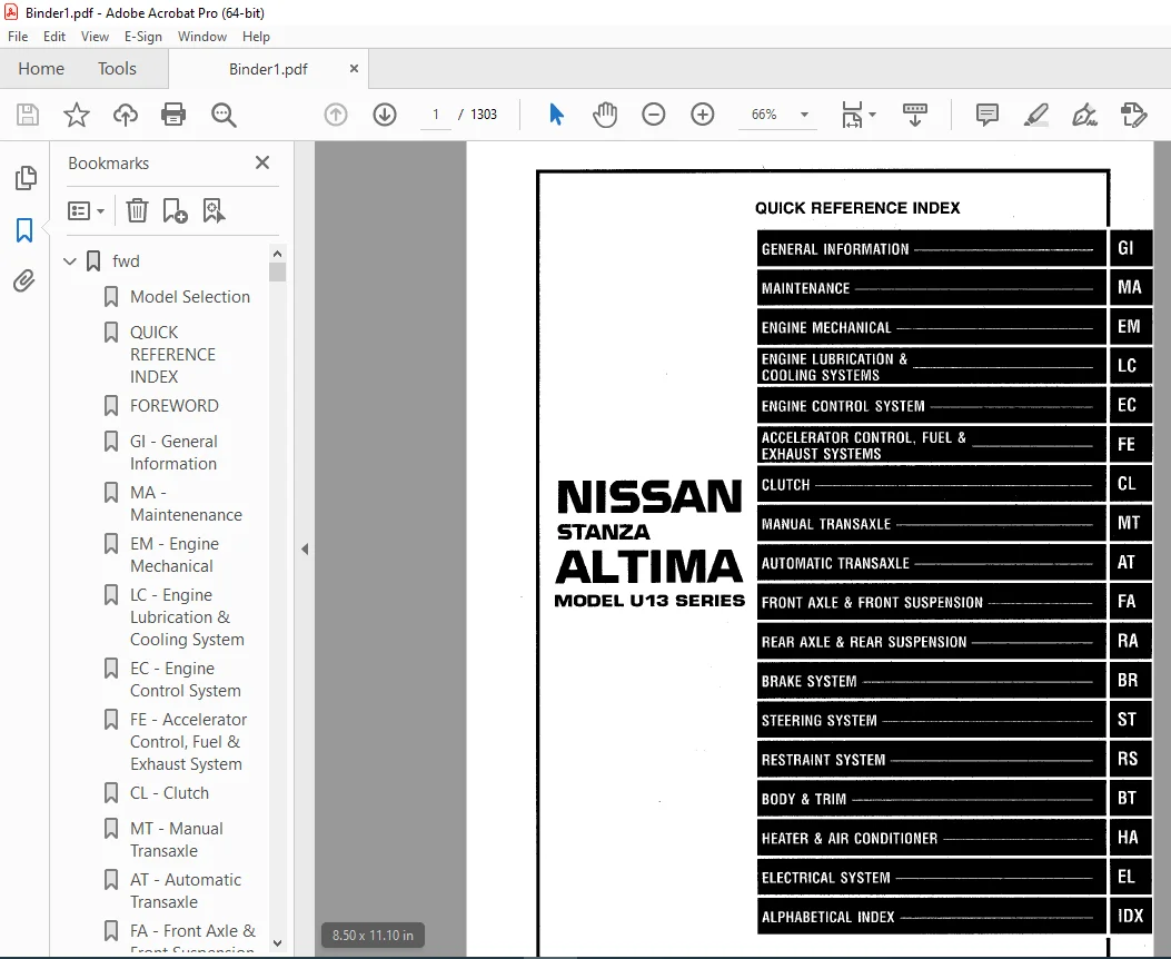
QUICK REFERENCE INDEX 1
FOREWORD 2
GI – General Information 0
MA – Maintenenance 0
EM – Engine Mechanical 0
LC – Engine Lubrication & Cooling System 0
EC – Engine Control System 0
FE – Accelerator Control, Fuel & Exhaust System 0
CL – Clutch 0
MT – Manual Transaxle 0
AT – Automatic Transaxle 0
FA – Front Axle & Front Suspension 0
RA – Rear Axle & Rear Suspension 0
BR – Brake System 0
ST – Steering System 0
RS – Restraint System 0
BT – Body & Trim 0
HA – Heater & Air Conditioner 0
EL – Electrical System 0
IDX – Alphabetical Index 1
Foldout 0
Quick Reference Chart 3
at 4
QUICK REFERENCE INDEX 0
TABLE OF CONTENTS 4
PREPARATION AND PRECAUTIONS 6
Special Service Tools 6
Commercial Service Tools 9
Service Notice 10
Precautions For Supplemental Restraint System (SRS) “AIR BAG” 11
DESCRIPTION 12
Cross-sectional View 12
Hydraulic Control Circuit 13
Shift Mechanism 14
Construction 14
Function of Clutch And Brake 14
Operation of Clutch And Brake 15
Control System 16
A/T Control Unit Function 17
Input/Output Signal of A/T Control Unit 17
TROUBLE DIAGNOSES 18
How to Perform Trouble Diagnoses for Quick and Accurate Repair 18
Work Flow 18
Information From Customer 19
Diagnostic Worksheet 20
Remarks 22
Fail-Safe 22
ATF Cooler Service 22
OBD-II Self-Diagnosis 22
Diagnostic Trouble Code (DTC) Chart 24
A/T Related Items 24
Diagnosis by CONSULT 26
Notice 26
Self-Diagnostic Resiult Test Mode 26
Data Monitor Diagnostic Test Mode 27
Data Analysis 29
Preliminary Check 30
A/T Fluid Check 30
Road Test 30
Shift Schedule 41
A/T Electrical Parts Location 42
Schematic 43
Wiring Diagram – AT – 44
Self-diagnosis 51
SELF-DIAGNOSTIC PROCEDURE WITH CONSULT 51
SELF-DIAGNOSTIC PROCEDURE WITH GENERIC SCAN TOOL (GST) 52
SELF-DIAGNOSTIC PROCEDURE WITHOUT CONSULT OR GST 52
Judgement of Self-Diagnosis Code Indicated By OD OFF Indicator Lamp 54
HOW TO ERASE DTC WITH CONSULT 56
HOW TO ERASE DTC WITH GENERIC SCAN TOOL 56
HOW TO ERASE DTC WITHOUT CONSULT OR GST 56
DTC P0720 Vehicle Speed Sensor-A/T (Revolution Sensor) Circuit Check 57
Vehicle Speed Sensor-MTR Circuit Check 59
DTC P1705 Throttle Position Sensor Circuit Check 61
DTC P0750 Shift Solenoid Valve A Circuit Check 63
DTC P0755 Shift Solenoid Valbe B Circuit Check 65
DTC P1760 Overrun Clutch Solenoid Valve Circuit Check 67
DTC P0740 Torque Converter Clutch Solenoid Valve Circuit Check 69
DTC P0710 Fluid Temperature Sensor Circuit And A/T Control Unit Power Source Circuit Checks 71
DTC P0725 Engine Speed Signal Circuit Check 74
DTC P0745 Line Pressure Solenoid Valve Circuit Check 76
DTC P0705 Inhibitor, Overdrive And Throttle Position Switch Circuit Checks 78
DTC P0731 Improper Shifting To 1st Gear Position 82
DTC P0732 Improper Shifting To 2nd Gear Position 84
DTC P0733 Improper Shifting To 3rd Gear Position 86
DTC P0734 Improper Shifting To 4th Gear Position Or Improper Torque Converter Clutch Operation 88
Diagnostic Procedures 92
Electrical Components Inspection 107
Inspection of A/T Control Unit 107
A/T Control Unit Inspection Table 107
Solenoid Valves And Fluid Temperature Sensor 111
Overdrive Switch 112
Inhibitor Switch 112
Revolution Sensor 113
Dropping Resistor 113
Throttle Position Switch 113
Final Check 114
Stall Testing 114
Pressure Testing 117
Line pressure test procedure 117
Symptom Chart 119
TROUBLE DIAGNOSES – A/T Shift Lock System 122
Description 122
Shift Lock System Electrical Parts Location 122
Wiring Diagram – SHIFT – 123
Diagnostic Procedure 124
Key Interlock Cable 126
Component Check 127
Shift Lock Solenoid 127
Park Position Switch 127
ASCD Cancel Or A/T Shift Lock Switch 128
ON-VEHICLE SERVICE 129
Control Valve Assembly and Accumulator 129
Revolution Sensor Replacement 130
Inhibitor Switch Adjustment 130
Control Cable Adjustment 131
Differential Side Oil Seal Replacement 131
REMOVAL AND INSTALLATION 132
MAJOR OVERHAUL 135
Oil Channel 138
DISASSEMBLY 139
REPAIR FOR COMPONENT PARTS 153
Manual Shaft 153
Oil Pump 155
Control Valve Assembly 159
Control Valve Upper Body 167
Control Valve Lower Body 171
Reverse Clutch 173
High Clutch 176
Forward Clutch and Overrun Clutch 180
Low & Reverse Brake 186
Rear Internal Gear, Forward Clutch Hub and Overrun Clutch Hub 188
Output Shaft, Idler Gear, Reduction Pinion Gear and Bearing Retainer 192
Band Servo Piston Assembly 197
Final Drive – RE4F04A 202
Final Drive – RE4F04V 206
ASSEMBLY 211
Assembly 1 211
Adjustment 1 211
Differential Side Bearing Preload 211
Reduction Pinion Gear Bearing Preload 213
Output Shaft End Play 215
Assembly 2 217
Adjustment 2 223
Total End Play 223
Assembly 3 225
SERVICE DATA AND SPECIFICATIONS (SDS) 231
General Specifications 231
Specifications and Adjustments 231
Final Drive 234
Planetary Carrier and Oil Pump 235
Input Shaft 235
Reduction Pinion Gear 236
Reverse Clutch End Play 236
Accumulator 236
Band Servo 237
Removal and Installation 237
Output Shaft 237
Bearing Retainer 237
Total End Play 237
br 238
QUICK REFERENCE INDEX 0
TABLE OF CONTENTS 238
PRECAUTIONS AND PREPARATION 240
Precautions 240
Supplemental Restraint System (SRS) “AIR BAG” 240
Brake System 240
Commercial Service Tools 241
CHECK AND ADJUSTMENT 242
Checking Brake Fluid Level 242
Checking Brake Line 242
Changing Brake Fluid 242
AIR BLEEDING 243
Bleeding Procedure 243
BRAKE HYDRAULIC LINE 244
Removal 244
Inspection 244
Installation 244
CONTROL VALVE 245
Proportioning Valve 245
Inspection 245
Removal (Separated type) 245
Installation (Separated type) 246
Removal And Installation (Built-in type) 246
BRAKE PEDAL AND BRACKET 247
Removal and Installation 247
Inspection 247
Adjustment 247
MASTER CYLINDER 249
Removal 249
Disassembly 249
Inspection 250
Assembly 250
Installation 251
BRAKE BOOSTER 252
On-vehicle Service 252
Operating Check 252
Airtight Check 252
Removal 252
Inspection 253
Output Rod Length Check 253
Installation 253
VACUUM HOSE 254
Removal and Installation 254
Inspection 254
Hoses And Connectors 254
Check Valve 254
FRONT DISC BRAKE 255
Pad Replacement 255
Removal 256
Disassembly 257
Inspection – Caliper 257
Cylinder Body 257
Piston 257
Slide Pin, Pin Bolt And Pin Boot 257
Inspection – Rotor 258
Runout 258
Thickness 258
Assembly 258
Installation 258
REAR DRUM BRAKE 259
Inspection – Wheel Cylinder 261
Wheel Cylinder Overhaul 261
Inspection – Drum 261
Inspection – Lining 262
Installation 262
REAR DISC BRAKE 264
Pad Replacement 264
Removal 266
Disassembly 266
Inspection – Caliper 267
Cylinder Body 267
Torque Member 267
Piston 267
Slide Pin, Pin Bolt and Pin Boot 268
Inspection – Rotor 268
Rubbing Surface 268
Runout 268
Thickness 268
Assembly 268
Installation 270
PARKING BRAKE CONTROL 271
Removal and Installation 271
Inspection 271
Adjustment 272
ANTI-LOCK BRAKE SYSTEM 273
Purpose 273
Operation 273
System Components 274
System Description 274
Sensor 274
Control Unit 274
Removal and Installation 275
Front Wheel Sensor 275
Rear Wheel Sensor 275
Control Unit 276
Actuator 276
Actuator Relays 276
TROUBLE DIAGNOSES 277
How to Perform Trouble Diagnoses for Quick and Accurate Repair 277
Introduction 277
Preliminary Check 278
Component Parts and Harness Connector Location 279
Circuit Diagram for Quick Pinpoint Check 280
Wiring Diagram – ABS – 281
Self-diagnosis 285
Function 285
Self-Diagnosis Procedure 285
How To Read Self- Diagnostic Results (Malfunction codes) 286
Hot To Erase Self-Diagnostic Results (Malfunction codes) 286
Malfunction Code/Symptom Chart 287
Ground Circuit Check 288
Actuator Motor Ground 288
Control Unit Ground 288
Relay Box Ground 288
Diagnostic Procedure 1 (Not self-diagnostic item) 289
Diagnostic Procedure 2 (Not Self-diagnostic item) 290
Diagnostic Procedure 3, Actuator Solenoid Valve 293
Diagnostic Procedure 4, Wheel Sensor Or Rotor 294
Diagnostic Procedure 5, Motor Relay Or Motor 296
Diagnostic Procedure 6, Solenoid Valve Relay 299
Diagnostic Procedure 7, Power Supply (Low voltage) 301
Diagnostic Procedure 8, Stop Lamp Switch Circuit 302
Diagnostic Procedure 9, Control Unit 302
Diagnostic Procedure 10, Symptom: Pedal vibration and noise 303
Diagnostic Procedure 11, Symptom: Long stopping distance 303
Diagnostic Procedure 12, Symptom: Unexpected pedal action 304
Diagnostic Procedure 13, Symptom: ABS does not work 304
Diagnostic Procedure 14, Symptom: ABS works frequently 305
Electrical Components Inspection 306
Wheel Sensor 306
Motor Relay 306
Solenoid Valve Relay 306
SERVICE DATA AND SPECIFICATIONS (SDS) 307
General Specifications 307
Inspection and Adjustment 307
Disc Brake 307
Drum Brake 307
Brake Pedal 307
Parking Brake 307
bt 308
QUICK REFERENCE INDEX 0
TABLE OF CONTENTS 308
GENERAL SERVICING 309
Precautions 309
Supplemental Restraint System (SRS) “AIR BAG” 309
Clip Fastener 310
BODY END 313
Body Front End 313
Removal – Front bumper assembly 313
Body Rear End and Opener 315
Removal – Rear bumper assembly 315
DOOR 317
Front Door 317
Rear Door 318
INSTRUMENT PANEL 319
Removal – Instrument panel assembly 319
INTERIOR TRIM 322
Side and Floor Trim 322
Door Trim 323
Roof Trim 325
Luggage Room Trim 326
EXTERIOR 327
1 Front hood Insulator 328
2 Cowl top grille and cowl top front sealing rubber 328
3 Front windshield molding 328
3 Windshield upper and side molding 329
4 Sunroof lid weatherstrip 329
5 Body side drip weathersrtip 329
6 Door weatherstrip 330
7 Body side welt 330
8 Door waist outside molding 330
9 Front door corner cover 331
10 Rear windshield molding 331
11 Trunk lid weatherstrip 331
12 Rear combination lamp 332
13 Side guard molding 332
14 Fender and Center mudguard 333
15 Front door parting seal 334
SEAT 335
Front Seat 335
Rear Seat 336
SUNROOF 337
Removal 338
Adjustment 339
WINDSHIELD AND WINDOWS 340
Removal 340
Intallation 340
Windshield and Rear Window 341
Repairing Water Leaks For Windshield 341
Quarter Window 342
Removal 342
MIRROR 343
Door Mirror 343
Removal and Installation 343
Rearview Mirror 344
Removal 344
Installation 344
REAR AIR SPOILER 345
BODY ALIGNMENT 346
Engine Compartment 346
Underbody 348
cl 350
QUICK REFERENCE INDEX 0
TABLE OF CONTENTS 350
PRECAUTIONS AND PREPARATION 351
Precautions 351
Special Service Tools 351
Commercial Service Tools 351
CLUTCH SYSTEM – Hydraulic Type 352
INSPECTION AND ADJUSTMENT 353
Adjusting Clutch Pedal 353
Bleeding Procedure 354
HYDRAULIC CLUTCH CONTROL 355
Clutch Master Cylinder 355
Operating Cylinder 356
CLUTCH RELEASE MECHANISM 357
CLUTCH DISC AND CLUTCH COVER 358
Clutch Disc 358
Clutch Cover and Flywheel 359
SERVICE DATA AND SPECIFICATIONS (SDS) 360
General Specifications 360
Inspection and Adjustment 360
ec 361
QUICK REFERENCE INDEX 0
TABLE OF CONTENTS 361
PRECAUTIONS AND PREPARATION 363
Special Service Tools 363
Supplemental Restraint System (SRS) “AIR BAG” 363
Precautions for On-Board Diagnostic (OBD) System of Engine and A/T 364
Engine Fuel & Emission Control System 365
Precautions 366
ENGINE AND EMISSION CONTROL OVERALL SYSTEM 368
Circuit Diagram 368
System Description 369
ECCS Component Parts Location 371
Vacuum Hose Drawing 374
Air Assisted Injector System Hose Drawing 375
System Chart 376
ENGINE AND EMISSION BASIC CONTROL SYSTEM DESCRIPTION 377
Multiport Fuel Injection (MFI) System 377
Distributor Ignition (DI) System 380
Air Conditioning Cut Control 382
Fuel Cut Control (at no load & high engine speed) 382
EVAPORATIVE EMISSION SYSTEM 383
POSITIVE CRANKCASE VENTILATION 385
BASIC SERVICE PROCEDURE 386
Fuel Pressure Release 386
Fuel Pressure Check 386
Fuel Pressure Regulator Check 387
Injector Removal and Installation 387
Idle Speed/Ignition Timing/Idle Mixture Ratio Adjustment 388
ON-BOARD DIAGNOSTIC SYSTEM DESCRIPTION 394
Introduction 394
Two Trip Detection Logic 394
Diagnostic Trouble Code (DTC) 394
How To Read DTC 394
How To Erase DTC 394
HOW TO ERASE DTC (With CONSULT) 394
HOW TO ERASE DTC (Without CONSULT) 395
Freeze Frame Data 395
Malfunction Indicator Lamp (MIL) 396
On-Board Diagnostic System Function 396
How To Switch Diagnostic Test Modes 397
OBD System Operation Chart 399
CONSULT 404
Generic Scan Tool (GST) 416
TROUBLE DIAGNOSIS – Introduction 418
TROUBLE DIAGNOSIS – Work Flow 420
TROUBLE DIAGNOSIS – Basic Inspection 422
TROUBLE DIAGNOSIS – General description 425
Diagnostic Trouble Code (DTC) Chart 425
Fail-Safe Chart 436
Symptom Matrix Chart (For New CT/CS) 437
Symptom Matrix Chart (For Old CT/CS) 440
CONSULT Reference Value In Data Monitor Mode 443
Major Sensor Reference Graph in Data Monitor Mode 445
ECM Terminals and Reference Value 448
TROUBLE DIAGNOSIS FOR POWER SUPPLY 454
DTC P0100, Mass Air Flow Sensor (MAFS) (DTC: 0102) 457
DTC P0110, Intake Air Temperature Sensor (DTC: 0401) 462
DTC P0115, Engine Coolant Temperature Sensor (ECTS) (DTC: 0103) 469
DTC P0120, Throttle Position Sensor (DTC: 0403) 473
DTC P0125, Engine Coolant Temperature (ECT) Sensor (DTC: 0908) 478
DTC P0130, Front Oxygen Sensor (Front O2S)* (DTC: 0303) 483
DTC P0130, Closed Loop Control (DTC: 0307) 490
DTC P0135, Front Heated Oxygen Sensor Heater (DTC: 0901) (For California models) 491
DTC P0136, Rear Heated Oxygen Sensor (Rear HO2S) (DTC: 0707) 494
DTC P0141, Rear Heated Oxygen Sensor Heater (DTC: 0902) (For California Models) 502
DTC P0170, Fuel Injection System Function (DTC: 0706) (For Non-California models) 506
DTC P0171, Fuel Injection System Function (Lean side) (DTC: 0115) (For California models) 511
DTC P0172, Fuel Injection System Function (Rich side) (DTC: 0114) (For California models) 516
DTC P0300 – P0304, No 4 – 1 Cylinder Misfire, Multiple Cylinder Misfire (DTC: 0701 – 0605) 521
DTC P0325, Knock Sensor (KS) (DTC: 0304) 525
DTC P0335, Crankshaft Position Sensor (CKPS) (OBD) (DTC: 0802) 528
DTC P0340, Camshaft Sensor (CMPS)(DTC: 0101) 532
DTC P0400, EGR Function (DTC: 0302) 537
DTC P0402, EGRC-BPT Valve Function (DTC: 0306) 546
DTC P0420, Three Way Catalyst Function (DTC: 0702) 548
DTC P0500, Vehicle Speed Sensor (VSS) (DTC: 0104) 551
DTC P0505, Idle Air Control Valve (IACV) – Auxiliary Air Control (AAC) Valve (DTC: 0205) 555
DTC P0600, A/T Control 559
DTC P0605, Engine Control Module (ECM)-ECCS Control Module (DTC: 0301) 562
DTC P0705, Park/Neutral Position Switch (DTC: 1003) 564
DTC P1320, Ignition Signal (DTC: 0201) 571
DTC P1336, Crankshaft Position Sensor (CDPS) (OBD) (DTC: 0905) 576
DTC P1400, EGR valve and EVAP Canister Purge Control Solenoid Valve (DTC: 1005) 580
DTC P1401, EGR Temperature Sensor (DTC: 0305) 584
DTC P1605, A/T Diagnosis Communication line (DTC: 0804) 589
DTC P1900, Cooling Fan (DTC: 1308 California models, 0208 Non-California models) 592
TROUBLE DIAGNOSIS FOR NON-DETECTABLE ITEMS 604
Injector 604
Start Signal 607
Fuel Pump 609
Power Steering Oil Pressure Switch 614
IAVC-Air Regulator 617
IAVC-FICD Solenoid Valve 618
Rear Window Defogger Signal 622
Air Assisted Injector System (A/T models for California) 624
Air Cut Valve 624
MIL & Data Link Connectors 625
TROUBLE DIAGNOSIS – Index 626
Alphabetical & P No Index for DTC 626
SERVICE DATA AND SPECIFICATIONS (SDS) 627
General Specifications 627
Inspection and Adjustment 627
el 629
QUICK REFERENCE INDEX 0
TABLE OF CONTENTS 629
PRECAUTIONS 632
Supplemental Restraint Sytem (SRS) “AIR BAG” 632
HARNESS CONNECTOR 633
Description 633
STANDARDIZED RELAY 634
Description 634
POWER SUPPLY ROUTING 636
Schematic 636
Wiring Diagram – POWER – 637
Fuse 643
Fusible Link 643
Circuit Breaker Inspection 643
GROUND DISTRIBUTION 644
BATTERY 648
How to Handle Battery 648
Memory Reset 650
Service Data and Specifications (SDS) 651
STARTING SYSTEM 652
System Description 652
Wiring Diagram – START – 654
Starter 656
Pinion/Clutch Check 658
Service Data and Specifications (SDS) 658
CHARGING SYSTEM 659
System Description 659
Wiring Diagram – CHARGE – 660
Trouble Diagnoses 661
Generator 662
Service Data and Specifications (SDS) 663
COMBINATION SWITCH 664
Combination Switch/Check 664
Combination Switch/Replacement 665
Steering Switch/Check 666
HEADLAMP 667
System Description (For USA) 667
Wiring Diagram (For USA) – H/LAMP – 668
Trouble Diagnoses (For USA) 669
System Description (For Canada) 670
Operation (Daytime light system for Canada) 671
Schematic (For Canada) 672
Wiring Diagram (For Canada) – DTRL – 673
Trouble Diagnoses (For Canada) 676
Bulb Replacement 678
Aiming Adjustment 678
EXTERIOR LAMP 680
Back-up Lamp/Wiring Diagram – BACK/L – 680
Clearance, License, Tail and Stop Lamps/Wiring Diagram – TAIL/L – 681
Front Fog Lamp/System Description 684
Front Fog Lamp/Wiring Diagram – F/FOG – 685
Turn Signal and Hazard Warning Lamps/System Description 686
Turn Signal and Hazard Warning Lamps/Wiring Diagram – TURN – 688
Turn Signal and Hazard Warning Lamps/Trouble Diagnoses 690
Cornering Lamp/System Description 691
Cornering Lamp/Wiring Diagram – CORNER – 692
Combination Flasher Unit Check 693
Bulb Specifications 693
INTERIOR LAMP 694
Illumination/System Description 694
Illumination/Schematic 695
Illimination/Wiring Diagram – ILL – 696
Interior, Personal and Trunk Room Lamps/Wiring Diagram – INT/L – 699
METERS AND GAUGES 700
System Description 700
Combination Meter 701
Speedometer, Tachometer, Temp and Fuel Gauges/Wiring Diagram – METER – 702
Inspection/Fuel Gauge and Water Temperature Gauge 703
Inspection/Tachometer 704
Inspection/Speedometer and Vehicle Speed Sensor 705
Inspection/Speedometer and Fuse 706
Fuel Tank Gauge Unit Check 707
Fuel Warning Lamp Sensor Check 707
Thermal Transmitter Check 707
Oil Pressure Switch Check 707
Vehicle Speed Sensor Signal Check 708
WARNING LAMPS AND CHIME 709
Warning Lamps/System Description 709
Warning Lamps Schematic 710
Warning Lamps/Wiring Diagram – WARN – 711
Warning Chime/System Description 714
Warning Chime/Wiring Diagram – CHIME – 715
Diode Check 716
Warning Chime Check 716
TIME CONTROL SYSTEM 717
System Description 717
Schematic 719
Wiring Diagram – TIME – 720
Trouble Diagnoses 723
Main Power Supply And Ground Circuit Check 725
Diagnostic Procedures 726
WIPER AND WASHER 732
System Description 732
Front Wiper and Washer/Wiring Diagram – WIPER – 734
Installation 736
Washer Nozzle Adjustment 737
POWER WINDOW 738
System Description 738
Component Layout 741
Wiring Diagram – WINDOW – 742
Trouble Diagnoses 744
POWER DOOR LOCK 745
System Description 745
Schematic 746
Wiring Diagram – D/LOCK – 747
Trouble Diagnoses 750
Operative Condition 750
Symptom Chart 751
Main Power Supply And Ground Circuit Check 752
Diagnostic Procedure 1 – Door Switch 752
Diagnostic Procedure 2 – Ignition key switch 753
Diagnostic Procedure 3 – Lock & unlock switch 753
Diagnostic Procedure 4 – Door key cylinder switch 754
Diagnostic Procedure 5 – Front door unlock sensor 755
Diagnostic Procedure 6 – Door lock actuator 756
MIRROR 757
Wiring Diagram – MIRROR – 757
SUNROOF 758
System Description 758
Wiring Diagram – SROOF – 759
HORN, LIGHTER, CLOCK 760
Wiring Diagram – HORN – 760
REAR WINDOW DEFOGGER 761
System Description 761
Wiring Diagram – DEF – 762
Filament Check 763
Filament Repair 764
AUDIO AND POWER ANTENNA 765
Audio/System Description 765
Audio/Schematic 766
With Active Speaker Audio System 766
Audio/Wiring Diagram – AUDIO – 767
With Active Speaker Audio System 767
Without Active Speaker Audio System 770
Power Antenna/System Description 771
Location of Antenna 771
Power Antenna/Wiring Diagram – P/ANT – 772
Trouble Diagnoses 773
Antenna Rod Replacement 775
Window Antenna Repair 776
AUTOMATIC SPEED CONTROL DEVICE (ASCD) 777
System Description 777
Component Parts and Harness Connector Location 779
Schematic 780
Wiring Diagram – ASCD – 781
Trouble Diagnoses 786
Symptom Chart 786
Diagnostic Procedures 787
ASCD Wire Adjustment 794
Electrical Components Inspection 795
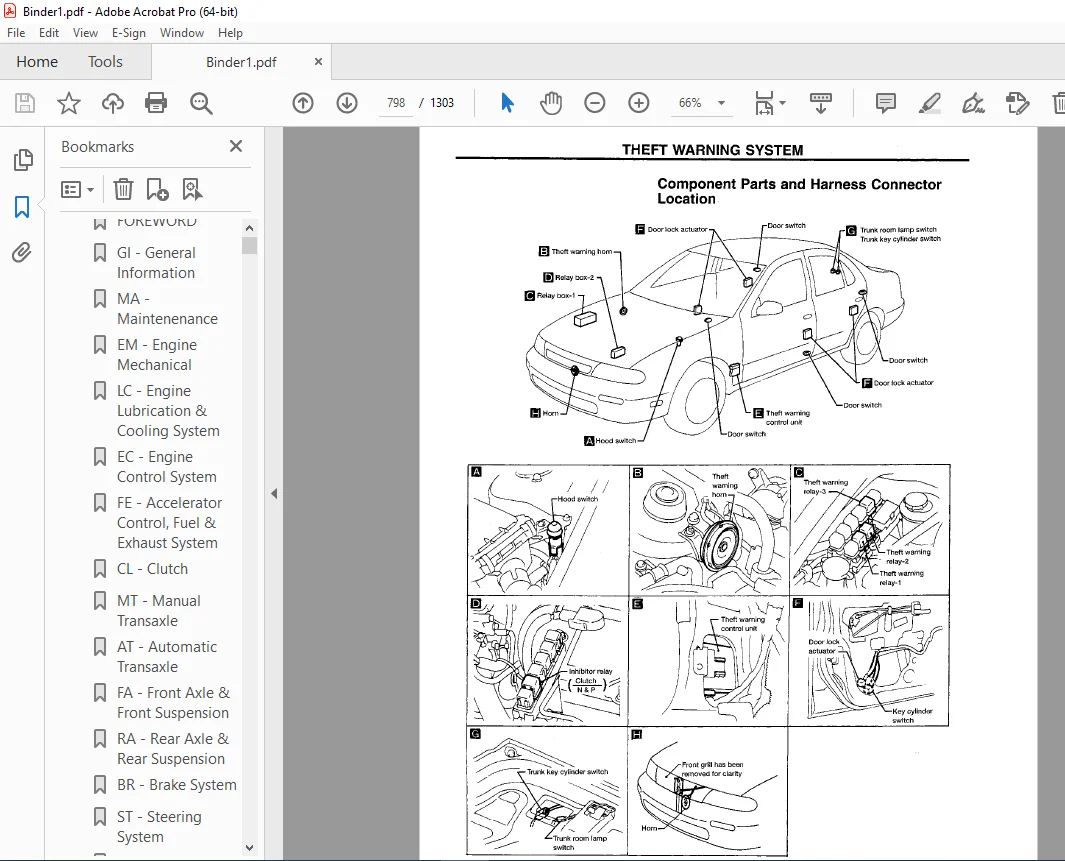
THEFT WARNING SYSTEM 798
Component Parts and Harness Connector Location 798
Schematic 800
Wiring Diagram – THEFT – 802
Trouble Diagnoses 809
System Operation Check 809
Power Supply And Ground Circuit Check 811
Diagnostic Procedures 812
Electrical Components Inspection 823
LOCATION OF ELECTRICAL UNITS 825
Engine Compartment 825
Passenger Compartment 826
HARNESS LAYOUT 827
Outline 827
Engine Room Harness 828
Engine Compartment 828
Passenger Compartment 830
Main Harness 832
Body Harness 834
Engine Control Harness 836
Engine Harness No 2 838
Room Lamp Harness 839
Air Bag Harness 840
Tail Harness 841
Door Harness (LH side) 842
Front 842
Rear 842
Door Harness (RH side) 843
Front 843
Rear 843
SUPER MULTIPLE JUNCTION (SMJ) 0
Installation 0
Terminal Arrangement 1
JOINT CONNECTOR (J/C) 2
Location 2
Terminal Arrangement 2
FUSE BLOCK/FUSIBLE LINK AND FUSE BOX 3
Fuse Arrangement 3
CONTROL UNITS/MODULE 4
em 844
QUICK REFERENCE INDEX 0
TABLE OF CONTENTS 844
PRECAUTIONS 845
Parts Requiring Angular Tightening 845
Liquid Gasket Application Procedure 845
PREPARATION 846
Special Service Tools 846
Commercial Service Tools 849
OUTER COMPONENT PARTS 850
Except A/T Models For California 850
A/T Models For California 851
COMPRESSION PRESSURE 854
Measurement of Compression Pressure 854
OIL PAN 855
Removal 855
Installation 857
TIMING CHAIN 860
Liquid gasket application places 861
Removal 862
Upper Timing Chain 862
Lower Timing Chain 865
Inspection 865
Installation 865
Lower Timing Chain 865
Upper Timing Chain 866
OIL SEAL REPLACEMENT 869
Valve Oil Seal 869
Front Oil Seal 869
Rear Oil Seal 870
ACCEL-DRUM UNIT 871
Adjustment 871
CYLINDER HEAD 873
Removal and Installation 874
Disassembly 874
Inspection 874
Cylinder Head Distortion 874
Camshaft Visual Check 875
Camshaft Runout 875
Camshaft Height 875
Camshaft Journal Clearance 875
Camshaft End Play 876
Camshaft Sprocket Runout 876
Valve Guide Clearance 876
Valve Guide Replacement 877
Valve Seats 878
Replacing Valve Seat For Service Parts 878
Valve Dimensions 879
Valve Spring 879
Valve Lifter and Valve Shim 879
Assembly 880
Valve Clearance 880
ENGINE REMOVAL 883
Removal 884
Installation 885
CYLINDER BLOCK 886
Disassembly 887
Piston And Crankshaft 887
Inspection 888
Piston And Piston Pin Clearance 888
Piston Ring Side Clearance 888
Piston Ring End Gap 888
Connecting Rod Bend And Torsion 889
Cylinder Block Distortion 889
Piston-To-Bore Clearance 889
Crankshaft 890
Bearing Clearance 891
Connecting Rod Bushing Clearance (Small end) 893
Replacement of Connecting Rod Bushing (Small end) 894
Flywheel/Drive Plate Runout 894
Assembly 894
Piston 894
Crankshaft 895
Replacing Pilot Bushing 896
SERVICE DATA AND SPECIFICATIONS (SDS) 897
General Specifications 897
Inspection and Adjustment 897
fa 906
QUICK REFERENCE INDEX 0
TABLE OF CONTENTS 906
PRECAUTIONS AND PREPARATION 907
Precautions 907
Special Service Tools 907
Commercial Service Tools 908
FRONT AXLE AND FRONT SUSPENSION 909
ON-VEHICLE SERVICE 910
Front Axle and Front Suspension Parts 910
Front Wheel Bearing 911
Front Wheel Alignment 911
Drive Shaft 913
FRONT AXLE 914
Wheel Hub and Knuckle 915
Drive Shaft 919
FRONT SUSPENSION 926
Coil Spring and Strut Assembly 927
Stabilizer Bar 928
Transverse Link and Lower Ball Joint 929
SERVICE DATA AND SPECIFICATIONS (SDS) 931
General Specifications 931
Inspection and Adjustment 932
fe 933
QUICK REFERENCE INDEX 0
TABLE OF CONTENTS 933
PREPARATION 934
Special Service Tool 934
ACCELERATOR CONTROL SYSTEM 935
Accelerator Control System 935
Adjusting Accelerator Wire 935
FUEL SYSTEM 936
Fuel Tank 936
Fuel Pump and Gauge 937
EXHAUST SYSTEM 938
California Exhaust System 939
Federal Exhaust System 940
foldout 941
QUICK REFERENCE INDEX 0
ELECTRICAL SYSTEM 2
SUPER MULTIPLE JUNCTION (SMJ) 941
Installation 941
Terminal Arrangement 942
JOINT CONNECTOR (J/C) 943
Location 943
Terminal Arrangement 943
FUSE BLOCK/FUSIBLE LINK AND FUSE BOX 944
Fuse Arrangement 944
CONTROL UNITS/MODULE 945
gi 946
QUICK REFERENCE INDEX 0
TABLE OF CONTENTS 946
PRECAUTIONS 947
Supplemental Restraint System (SRS) “AIR BAG” 947
General Precautions 948
Precautions for Multiport Fuel Injection system or ECM Controlled Engine 949
Precautions for Three Way Catalyst 949
Engine Oils 949
Precautions for Fuel 951
Precautions for Air Conditioning 951
HOW TO USE THIS MANUAL 952
HOW TO READ WIRING DIAGRAMS 954
Sample/Wiring Diagram – EXAMPL – 954
Description 956
Wiring Diagram Codes (Cell Codes) 962
HOW TO PERFORM EFFICIENT DIAGNOSIS FOR AN ELECTRICAL INCIDENT 963
Work Flow 963
Incident Simulation Tests 964
Circuit Inspection 968
HOW TO FOLLOW FLOW CHART IN TROUBLE DIAGNOSES 974
How To Follow This Flow Chart 975
CONSULT CHECKING SYSTEM 977
Function and System Application 977
Lithium Battery Replacement 977
Checking Equipment 977
IDENTIFICATION INFORMATION 978
Model Variation 978
Identification Number 979
Dimensions 981
Wheels and Tires 981
LIFTING POINTS AND TOW TRUCK TOWING 982
Preparation 982
Board-on Lift 983
Garage Jack and Safety Stand 983
2-pole Lift 984
Tow Truck Towing 984
TIGHTENING TORQUE OF STANDARD BOLTS 986
SAE J1930 TERMINOLOGY LIST 987
ha 991
QUICK REFERENCE INDEX 0
TABLE OF CONTENTS 991
MANUAL AND AUTO 993
PRECAUTIONS AND PREPARATION 993
Precautions for Supplemental Restraint System (SRS) “AIR BAG” 993
Precautions for Working with HFC-134a (R-134a) 993
Precautions for Working with Refrigerants 994
Precautions for Refrigerant Connection 995
Precautions for Servicing Compressor 996
Special Service Tools 997
R-134a Service Tools and Equipment 998
Precautions for Service Equipment1000
DESCRIPTION1002
Refrigeration Cycle1002
Refrigerant Flow1002
Refrigerant System Protection1002
Triple-pressure switch1002
Pressure relief valve1002
Component Layout1003
Discharge Air Flow1004
MANUAL1005
DESCRIPTION1005
Control Operation1005
TROUBLE DIAGNOSES1006
How to Perform Trouble Diagnoses for Quick and Accurate Repair1006
Operational Check1007
Symptom Chart1009
Preliminary Check1011
Performance Test Diagnoses1017
Performance Chart1019
Trouble Diagnoses for Abnormal Pressure1020
Harness Layout1024
Schematic1026
Wiring Diagram – HEATER -1027
Wiring Diagram – A/C, M -1028
Main Power Supply and Ground Circuit Check1034
Diagnostic Procedures1035
Electrical Components Inspection1047
Conrol Linkage Adjustment1048
AUTO1051
DESCRIPTION1051
Introduction1051
Features1051
Control Operation1052
TROUBLE DIAGNOSIS1054
How to Perform Trouble Diagnoses for Quick and Accurate Repair1054
Operational Check1055
Symptom Chart1058
Self-diagnosis1062
Checking Procedure1063
Auxiliary Mechanism: Temperature setting timmer1069
Preliminary Check1070
Performance Test Diagnoses1078
Performance Chart1080
Trouble Diagnoses for Abnormal Pressure1081
Harness Layout1085
Schematic1087
Wiring Diagram – A/C, A -1088
Main Power Supply and Ground Circuit Check1094
Diagnostic Procedures1095
Electrical Components Inspection1111
Control Linkage Adjustment1112
SYSTEM DESCRIPTION1114
Overview of Control System1114
Control System Input Components1115
Potentio Temperature Control (PTC)1115
In-Vehicle Sensor1115
Aspirator1115
Ambient Sensor1116
Sunload Sensor1116
Control System Automatic Amplifier (Auto amp)1117
Control System Output Components1117
Air Mix Door Control (Automatic temperature control)1117
Air Mix Door Motor1119
Mode Door Control1120
Mode Door Motor1121
Intake Door Control1121
Intake Door Motor1122
Fan Speed Control1123
Automatic Mode1123
Starting Fan Speed Control1123
Blower Speed Compensation1124
Fan Control Amplifier1124
Blower Hi-Relay1125
Magnet Clutch Control1125
MANUAL AND AUTO1126
SERVICE PROCEDURES1126
Checking Refrigerant Leaks1126
Preliminary Check1126
Precautions for Handling Leak Detector1126
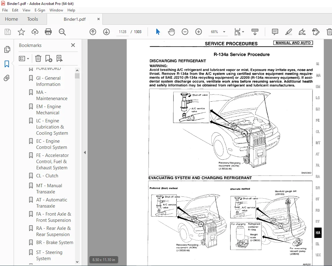
R-134a Service Procedure1128
Discharging Refrigerant1128
Evacuating System And Charging Refrigerant1128
Compressor Lubricant Quantity1130
Refrigerant Lines1132
Compressor Mounting1133
Fast Idle Control Device (FICD)1133
Compressor1134
Compressor Clutch1134
Removal1134
Inspection1135
Installation1136
Break-In Operation1137
Thermal Protector1137
Inspection1137
SERVICE DATA AND SPECIFICATIONS (SDS)1138
General Specifications1138
Compressor1138
Lubricant1138
Refrigerant1138
Inspection and Adjustment1138
Engine Idling Speed When A/C is On1138
Belt Tension1138
Compressor Clutch1138
idx1139
QUICK REFERENCE INDEX 0
lc1148
QUICK REFERENCE INDEX 0
TABLE OF CONTENTS1148
PRECAUTIONS1149
Liquid Gasket Application Procedure1149
PREPARATION1150
Special Service Tools1150
ENGINE LUBRICATION SYSTEM1151
Lubrication Circuit1151
Oil Pressure Check1152
Oil Pump1152
ENGINE COOLING SYSTEM1155
Cooling Circuit1155
System Check1155
Water Pump1156
Thermostat1158
Radiator1159
Overheating Cause Analysis1160
SERVICE DATA AND SPECIFICATIONS (SDS)1161
Engine Lubrication System1161
Engine Cooling System1161
ma1162
QUICK REFERENCE INDEX 0
TABLE OF CONTENTS1162
PREPARATION AND PRECAUTIONS1163
Precautions for Supplemental Restraint System (SRS) “AIR BAG”1163
GENERAL MAINTENANCE1164
PERIODIC MAINTENANCE1166
Schedule 11167
Schedule 21168
RECOMMENDED FLUIDS AND LUBRICANTS1169
Fluids and Lubricants1169
SAE Viscosity Number1169
Anti-freeze Coolant Mixture Ratio1170
ENGINE MAINTENANCE1171
Checking Drive Belts1171
Changing Engine Coolant1172
Checking Fuel Lines1173
Changing Fuel Filter1174
Changing Air Cleaner Filter1174
Changing Engine Oil1175
Changing Oil Filter1175
Changing Spark Plugs1176
Checking Vapor Lines1176
CHASSIS AND BODY MAINTENANCE1177
Checking Exhaust System1177
Checking Clutch Fluid Level and Leaks1177
Checking M/T Oil1177
Changing M/T Oil1177
Checking A/T Fluid1178
Changing A/T Fluid1178
Checking Brake Fluid Level and Leaks1179
Checking Brake Lines and Cables1179
Checking Disc Brake1179
Checking Drum Brake1179
Balancing Wheels1180
Tire Rotation1180
Checking Steering Gear and Linkage1180
Checking Power Steering Fluid and Lines1181
Lubricating Locks, Hinges and Hood Latches1182
Checking Seat Belts, Buckles, Retractors, Anchors and Adjusters1182
SERVICE DATA AND SPECIFICATIONS (SDS)1183
Engine Maintenance1183
Chassis and Body Maintenance1183
mt1184
QUICK REFERENCE INDEX 0
TABLE OF CONTENTS1184
PREPARATION1185
Special Service Tools1185
Commercial Service Tools1187
ON-VEHICLE SERVICE1188
Replacing Oil Seal1188
Differential Side Oil Seal1188
Striking Rod Oil Seal1188
Position Switch Check1189
Viscous Coupling Check1189
REMOVAL AND INSTALLATION1190
Removal1190
Installation1192
TRANSAXLE GEAR CONTROL1193
MAJOR OVERHAUL1194
Case Components1194
Gear Components1195
Shift Control Components1196
DISASSEMBLY1197
REPAIR FOR COMPONENT PARTS1200
Input Shaft and Gears1200
Mainshaft and Gears1205
Final Drive1209
Shift Control Components1213
Case Components1213
ADJUSTMENT1214
Input Shaft End Play and Differential Side Bearing Preload1214
Mainshaft Bearing Preload1215
ASSEMBLY1218
SERVICE DATA AND SPECIFICATIONS (SDS)1222
General Specifications1222
Inspection and Adjustment1223
Gear End Play1223
Clearance Between Baulk Ring And Gear 1st, 3rd, 4th & 5th1223
Reverse Baulk Ring1223
2nd baulk ring1223
Available Snap Ring 3rd & 4th synchronizer bar (At input shaft)1223
1st & 2nd synchronizer hub1223
5th main gear1223
Available Washer, Input shaft thrust washer1224
Differential side gear thrust washer – RS5F50A1224
Differential side gear thrust washer – RS5F50V1224
Available Shim1224
Bearing preload and end play1224
Turning torque (New bearing)1224
Mainshaft bearing adjusting shim1224
Table for selecting mainshaft adjusting shim(s)1225
Input shaft bearing adjusting shim1225
Table for selecting input shaft bearing adjusting shim(s)1225
Differential side bearing adjusting shim – RS5F50A1226
Table for selecting differential side bearing adjusting shim(s) – RS5F50A1226
Differential side bearing adjusting shim – RS5F50V1226
Table for selecting differential side bearing adjusting shim(s) – RS5F50V1226
ra1227
QUICK REFERENCE INDEX 0
TABLE OF CONTENTS1227
PRECAUTIONS AND PREPARATION1228
Precautions1228
Special Service Tools1228
Commercial Service Tools1228
REAR AXLE AND REAR SUSPENSION1229
ON-VEHICLE SERVICE1230
Rear Axle and Rear Suspension Parts1230
Rear Wheel Bearing1230
Rear Wheel Alignment1231
REAR AXLE1233
Wheel Hub1233
REAR SUSPENSION1235
Removal and Installation1236
Coil Spring and Strut Assembly1237
Parallel Link, Radius Link and Stabilizer Bar1239
SERVICE DATA AND SPECIFICATIONS (SDS)1240
General Specifications1240
Inspection and Adjustment1240
rs1241
QUICK REFERENCE INDEX 0
TABLE OF CONTENTS1241
PRECAUTION1242
Supplemental Restraint System (SRS) “AIR BAG”1242
SEAT BELTS1243
Front Seat Belt1244
Removal1245
Rear Seat Belt1246
Removal1246
SUPPLEMENTAL RESTRAINT SYSTEM (SRS)1247
Precautions for SRS “Air Bag” Service1247
Special Service Tools1247
Description1248
SRS Component Parts Location1248
Maintenance Items1249
Removal and Installation – Diagnoses Sensor Unit1250
Removal – Air Bag Module and Spiral Cable1251
Installation – Air Bag Module and Spiral Cable1252
Removal – Front Passenger Air Bag Module1253
Installation – Front Passenger Air Bag Module1254
Disposal of Air Bag Module1255
Checking Deployment Tool1255
Deployment Procedures For Air Bag Module (Outside of vehicle)1256
Deployment of Air Bag Module While Mounted In Vehicle1258
Disposing of Air Bag Module1258
TROUBLE DIAGNOSES – Supplemental Restraint System (SRS)1259
Wiring Diagram – SRS -1259
Schematic1261
How to Perform Trouble Diagnoses for Quick and Accurate Repair1262
Self-diagnosis1264
Diagnostic Procedures1264
Trouble Diagnoses for Air Bag Warning Lamp1278
Diagnostic Procedures1278
COLLISION DIAGNOSIS1280
SRS Inspection1280
st1281
QUICK REFERENCE INDEX 0
TABLE OF CONTENTS1281
PRECAUTIONS AND PREPARATION1282
Precautions1282
Special Service Tools1283
Commercial Service Tools1284
ON-VEHICLE SERVICE1285
Checking and Adjusting Drive Belts1285
Checking Fluid Level1285
Checking Fluid Leakage1285
Bleeding Hydraulic System1285
Checking Steering Wheel Turning Force1286
Checking Steering Wheel Play1287
Checking Neutral Position on Steering Wheel1287
Front Wheel Turning Angle1287
Checking Gear Housing Movement1287
Checking Hydraulic System1288
STEERING WHEEL AND STEERING COLUMN1289
Removal1289
Installation1290
Disassembly and Assembly1291
Inspection1292
POWER STEERING GEAR AND LINKAGE1293
Removal and Installation1293
Disassembly1296
Inspection1296
Assembly1296
POWER STEERING OIL PUMP1299
Disassembly and Assembly1299
Pre-disassembly Inspection1299
Disassembly1300
Inspection1300
Assembly1301
SERVICE DATA AND SPECIFICATIONS (SDS)1302
General Specifications1302
Inspection and Adjustment1302
PLEASE NOTE:
- This is the same manual used by the dealers to diagnose and troubleshoot your vehicle
- You will be directed to the download page as soon as the purchase is completed. The whole payment and downloading process will take anywhere between 2-5 minutes
- Need any other service / repair / parts manual, please feel free to contact [email protected] . We still have 50,000 manuals unlisted
G.P