1997-1999 Honda Prelude Service Manual – PDF DOWNLOAD
Original price was: $75.95.$29.95Current price is: $29.95.
1997-1999 Honda Prelude Service Manual – PDF DOWNLOAD
Description
1997-1999 Honda Prelude Service Manual – PDF DOWNLOAD
FILE DETAILS:
1997-1999 Honda Prelude Service Manual – PDF DOWNLOAD
Language : English
Pages : 1376
Downloadable : Yes
File Type : PDF
Size: 170 MB
IMAGES PREVIEW OF THE MANUAL:
DESCRIPTION:
1997-1999 Honda Prelude Service Manual – PDF DOWNLOAD
INTRODUCTION:
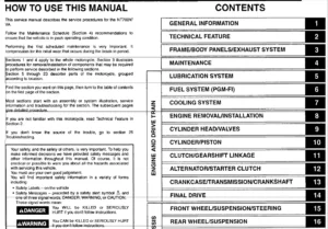
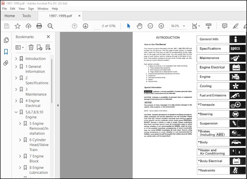
How to Use This Manual:
This manual contains information for the PRELUDE and
divided into 24 sections. The first page of each section is marked
with а Ыасk tab that lines up with its corresponding thumb index
tab оп this page and the back cover. You can quickly find the first
page of each section without looking through а full tаЫе of contents.
The symbols printed at the top corner of each page сап also
Ье used as а quick reference system.
Each section includes:
1. А tаЫе of contents, or an exploded view index showlng:
• Parts disassemЬly sequence.
• Bolt torques and thread sizes.
• Page references to descriptions in text.
2. DisassemЬly/assemЫy procedures and tools.
3. lnspection.
4. Testing/trouЫeshooting.
5. Repair.
6. Adjustments.
TABLE OF CONTENTS:
1997-1999 Honda Prelude Service Manual – PDF DOWNLOAD
Introduction 1
SRS Warning 2
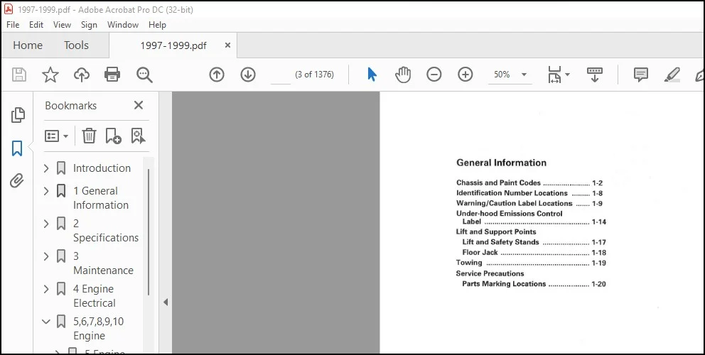
1 General Information 3
1-2 Chassis and Paint Codes 4
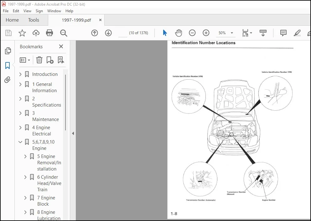
1-8 Identification Number Locations 10
1-9 Warning/Caution Label Locations 11
1-14 Under-Hood Emissions Control Label 16
Lift and Support Points 19
1-17 Lift and Safety Stands 19
1-18 Floor Jack 20
1-19 Towing 21
1-20 Service Precautions 22
2 Specifications 23
2-2 Standars and Service Limits 24
2-13 Design Specifications 35
2-16 Body Specifications 38
3 Maintenance 39
3-2 Lubrication Points 40
3-6 Maintenance Schedule for 1997 44
3-8 Maintenance Schedule for 1998 46
3-12 Maintenance Schedule for 1999 50
4 Engine Electrical 55
4-2 Special Tools 56
4-3 Starting System 57
4-3 Component Location Index 57
4-4 Circuit Diagram 58
4-5 Starter Test 59
4-6 Starter Solenoid Test 60
4-7 Starter Replacement 61
4-8 Starter Overhaul 62
4-9 Armature Inspection & Test 63
4-11 Starter Brush Holder Test 65
4-11 Starter Brush Inspection 65
4-12 Overrunning Clutch Inspection 66
4-12 Starter Reassembly 66
4-13 Performance Test 67
4-14 Ignition System 68
4-14 Component Location Index 68
4-15 Circuit Diagram 69
4-16 Ignition Timing Inspection 70
4-17 Distributor Replacement 71
4-18 Distributor Overhaul 72
4-19 Ignition Control Module (ICM) Input Test 73
4-20 Ignition Wire Inspection & Test 74
4-20 Ignition Coil Test 74
4-21 Spark Plug Inspection 75
4-22 Charging System 76
4-22 Component Location Index 76
4-23 Circuit Diagram 77
4-24 Troubleshooting 78
4-29 Alternator Replacement 83
4-30 Alternator Overhaul 84
4-31 Rectifier Test 85
4-31 Alternator Brush Inspection 85
4-32 Rotor Slip Ring Test 86
4-32 Stator Test 86
4-33 A/C Comp (Alternator) Belt Inspec & Adj 87
Cruise Control 88
5,6,7,8,9,10 Engine 99
5 Engine Removal/Installation 101
5-2 Engine Removal 102
5-10 Engine Installation 110
6 Cylinder Head/Valve Train 115
6-2 Special Tools 116
6-3 VTEC Control System 117
6-3 Troubleshooting Flowchart 117
6-6 VTEC Solenoid Valve Inspection 120
6-7 VTEC Rocker Arms 121
6-7 Manual Inspection 121
6-7 Inspection Using Special Tools 121
6-9 Valve Clearance Adjustment 123
6-11 Crankshaft Pulley & Pulley Bolt Replacement 125
6-12 Timing Belt & Timing Balancer Belt 126
6-12 Illustrated Index 126
6-13 Timing Belt Inspection 127
6-13 Timing Balancer Belt Inspection 127
6-14 Removal 128
6-16 Installation 130
6-21 CKP/TDC Sensors Replacement 135
6-22 Cylinder Head 136
6-22 Illustrated Index 136
6-24 Removal 138
6-38 Warpage 152
6-43 Installation 157
6-28 Rocker Arms and Shafts 142
6-28 Removal 142
6-30 Disassembly/Reassembly 144
6-31 Clearance Inspection 145
6-32 Rocker Arms 146
6-32 Inspection 146
6-42 Installation 156
6-32 Lost Motion Assemblies Inspection 146
6-33 Camshafts Inspection 147
6-35 Valves, Valve Springs & Valve Seats 149
6-35 Removal 149
6-41 Installation 155
6-37 Valve Seats, Reconditioning 151
6-38 Valve Guides 152
6-38 Valve Movement 152
6-39 Replacement 153
6-40 Reaming 154
7 Engine Block 161
7-2 Special Tools 162
7-3 Illustrated Index 163
7-7 Flywheel & Drive Plate: Replacement 167
7-7 Connecting Rod & Crankshaft: End Play 167
7-8 Main Bearings 168
7-8 Clearance 168
7-9 Selection 169
7-10 Connecting Rod Bearings 170
7-10 Clearance 170
7-11 Selection 171
7-12 Crankshaft, Balancer Shafts & Pistons: Removal 172
7-15 Crankshaft: Inspection 175
7-16 Pistons 176
7-16 Inspection 176
7-25 Installation 185
7-17 Cylinder Block 177
7-17 Inspection 177
7-18 Bore Honing 178
7-19 Piston Pins 179
7-19 Removal 179
7-20 Inspection 180
7-21 Installation 181
7-21 Connecting Rods: Selection 181
7-22 Piston Rings 182
7-22 End Gap 182
7-23 Replacement 183
7-23 Ring-to-Groove Clearance 183
7-24 Alignment 184
7-25 Crankshaft Oil Seal: Installation 185
7-26 Crankshaft & Balancer Shafts: Installation 186
7-31 Crankshaft & Balancer Shaft Oil Seal: Installation 191
7-32 Balancer Shafts: Inspection 192
8 Engine Lubrication 195
8-2 Special Tools 196
8-3 Illustrated Index 197
8-6 Engine Oil 200
8-6 Inspection 200
8-6 Replacement 200
8-7 Oil Filter: Replacement 201
8-10 Oil Pressure Switch: Testing 204
8-10 Oil Pressure: Testing 204
8-12 Oil Jet: Inspection 206
8-13 Oil Pump 207
8-13 Overhaul 207
8-14 Removal/Inspection/Installation 208
9 Intake Manifold/Exhaust System 213
9-2 Intake Manifold: Replacement 214
9-3 Exhaust Manifold: Replacement 215
9-4 Exhaust Pipe & Muffler: Replacement 216
10 Cooling 219
10-2 Radiator 220
10-2 Illustrated Index 220
10-4 Replacement 222
10-5 Engine Coolant Refilling & Bleeding 223
10-6 Cap Testing 224
10-6 Testing 224
10-7 Thermostat 225
10-7 Replacement 225
10-8 Testing 226
10-9 Water Pump 227
10-9 Illustrated Index 227
10-10 Inspection 228
10-10 Replacement 228
10-11 Fan Controls 229
10-11 Component Location Index 229
10-12 Circuit Diagram 230
10-13 Fan Motor Testing 231
10-13 Radiator Fan Switch Testing 231
10-14 Coolant Temperature Gauge 232
10-14 Gauge Testing 232
10-14 Sending Unit Testing 232
11 Fuel and Emissions 233
11-2 Special Tools 234
11-3 Component Locations Index 235
11-7 System Description 239
11-7 Vacuum Connections 239
11-13 Electrical Connections 245
11-24 System Connectors 256
11-36 Troubleshooting 268
11-36 Troubleshooting Procedures 268
11-43 Engine Control Module Terminal Arrangement 275
11-46 Diagnostic Trouble Code Chart 278
11-51 How to Read Flowcharts 283
11-52 PGM-FI System 284
11-52 System Description 284
11-54 Troubleshooting Flowcharts 286
11-54 Engine Control Module 286
11-58 Manifold Absolute Pressure Sensor 290
11-62 Intake Air Temperature Sensor 294
11-65 Engine Coolant Temperature Sensor 297
11-68 Throttle Position Sensor 300
11-72 Primary Heated Oxygen Sensor (Sensor 1) 304
11-76 Secondary Heated Oxygen Sensor (Sensor 2) 308
11-79 Heated Oxygen Sensor Heater 311
11-81 Fuel Supply System 313
11-83 Misfire Detected in One Cylinder 315
11-86 Random Misfire 318
11-87 Knock Sensor 319
11-88 Crankshaft Position/Top Dead Center Sensor 320
11-90 Vehicle Speed Sensor 322
11-91 Barometric Pressure Sensor 323
11-92 Electrical Load Sensor 324
11-95 Cylinder Position Sensor 327
11-97 ECM Internal Circuit 329
11-98 A/T Signal (SEFA/SEAF) 330
11-99 HO2S Replacement 331
11-100 Idle Control System 332
11-100 System Description 332
11-101 Troubleshooting Flowcharts 333
11-101 Idle Control System 333
11-103 Idle Air Control Valve 335
11-105 Air Conditioning Signal 337
11-107 Alternator FR Signal 339
11-108 Starter Switch Signal 340
11-109 Power Steering Pressure Switch Signal 341
11-111 Brake Switch Signal 343
11-112 A/T Gear Position Signal 344
11-114 Fast Idle Thermo Valve 346
11-115 Idle Speed Setting 347
11-116 Fuel Supply System 348
11-116 Fuel Lines 348
11-120 Fuel Tube/Quick Connect Fittings 352
11-123 System Description 355
11-123 Fuel Pressure 355
11-124 Fuel Injectors 356
11-126 Fuel Pressure Regulator 358
11-127 Fuel Filter 359
11-128 Fuel Pump 360
11-129 Fuel Gauge Sending Unit 361
11-132 PGM-FI Main Relay 364
11-135 Fuel Tank 367
11-137 Intake Air System 369
11-137 System Description 369
11-138 Air Cleaner 370
11-139 Throttle Cable 371
11-140 Throttle Body 372
11-142 Intake Control System 374
11-146 Intake Air Bypass Control System 378
11-150 Emission Control System 382
11-150 System Description 382
11-150 Tailpipe Emission 382
11-150 Three Way Catalytic Converter 382
11-152 Exhaust Gas Recirculation System 384
11-160 Positive Crankcase Ventilation System 392
11-161 Evaporative Emission Controls 393
12,13,14,15,16 Transaxle 429
12 Clutch 431
12-2 Special Tools 432
12-3 Illustrated Index 433
12-4 Clutch Pedal Adjustment 434
12-5 Clutch Master Cylinder Removal/Installation 435
12-6 Slave Cylinder Removal/Installation 436
12-7 Pressure Plate Removal/Inspection 437
12-8 Clutch Disc Removal/Inspection 438
12-9 Flywheel Inspection/Replacement 439
12-10 Clutch Disc, Pressure Plate Installation 440
12-11 Release Bearing 441
12-11 Removal/Inspection 441
12-11 Installation 441
13 Manual Transmission 443
13-2 Special Tools 444
13-3 Maintenance: Transmission Oil 445
13-3 Back-up Light Switch: Test/Replacement 445
13-4 Transmission Assembly 446
13-4 Removal 446
13-12 Installation 452
13-13 Gearshift Mechanism: Overhaul 455
13-14 Illustrated Index 456
13-16 Shift Arm Assembly 458
13-16 Index 458
13-17 Disassembly / Reassembly 459
13-19 Transmission Housing: Removal 461
13-20 Reverse Shift Fork: Clearance Inspection 462
13-21 Reverse Idler Gear: Removal 463
13-21 Mainshaft, Countershaft: Removal 463
13-22 Mainshaft Assembly 464
13-22 Index 464
13-23 Clearance Inspection 465
13-24 Disassembly 466
13-25 Inspection 467
13-26 Reassembly 468
13-27 Countershaft Assembly 469
13-27 Index 469
13-28 Clearance Inspection 470
13-30 Disassembly 472
13-31 Inspection 473
13-31 Reassembly 473
13-33 Shift Fork Assembly 475
13-33 Disassembly/Reassembly 475
13-34 Clearance Inspection 476
13-35 Syncro Sleeve, Syncro Hub 477
13-35 Inspection 477
13-35 Installation 477
13-36 Syncro Ring, Gear: Inspection 478
13-37 Differential 479
13-37 Index 479
13-37 Backlash Inspection (w/o ATTS) 479
13-38 Final Drive Gear Replacement (w/o ATTS) 480
13-38 Tapered Roller Bearing Replacement 480
13-39 Bearing outer Race Replacement 481
13-40 Tapered Roller Bearing Preload Adjustment 482
13-42 Oil Seal Replacement 484
13-43 Mainshaft Bearing/Oil Seal: Replacement 485
13-44 Countershaft Bearing: Replacement 486
13-45 Mainshaft Thrust Clearance: Adjustment 487
13-48 Transmission: Reassembly 490
14 Automatic Transmission 494
14-2 Special Tools 495
14-3 Description 496
14-6 Clutches 499
14-8 Power Flow 501
14-15 Electronic Control System 508
14-20 Hydraulic Control 513
14-24 Hydraulic Flow 517
14-39 Lock-up System 532
14-46 Shift Lever/Sequential Sportshift Mode Mechanism 539
14-47 Shift Lock/Reverse Lock Mechanism 540
14-48 Electrical System 541
14-48 TCM Circuit Diagram 541
14-50 TCM Terminal Voltage/Measuring Conditions 543
14-53 Component Locations 546
14-54 Troubleshooting Procedures 547
14-57 Symptom-to-Component Chart: Electrical System 550
14-60 Electrical Troubleshooting: Flowcharts 553
14-102 Lock-up Control Solenoid Valve 595
14-102 Shift Control Solenoid Valve A Assembly Test 595
14-102 Replacement 595
14-103 Shift Control Solenoid Valve B/C 596
14-103 Test 596
14-103 Replacement 596
14-104 A/T Clutch Pressure Control Solenoid 597
14-104 Valve A/B Test 597
14-105 Replacement 598
14-105 Mode Switch: Replacement 598
14-106 Mainshaft/Countershaft Speed Sensor: Replacement 599
14-106 2nd Clutch Pressure Switch: Replacement 599
14-107 A/T Gear Position Switch 600
14-107 Test 600
14-108 Replacement 601
14-110 A/T Gear Postion Indicator: Input Test 603
14-111 Interlock System 604
14-111 Key Interlock Solenoid Test 604
14-112 Shift Lock Solenoid Test 605
14-112 Shift Lock Solenoid Replacement 605
14-113 Park Pin Switch Test 606
14-113 Park Pin Switch Replacement 606
14-114 Hydraulic System 607
14-114 Symptom-to-Component Chart: Hydraulic System 607
14-118 Road Test 611
14-121 Stall Speed Test 614
14-122 Fluid Level: Checking/Changing 615
14-123 Pressure Testing 616
14-125 Transmission 618
14-125 Transmission Removal 618
14-130 Illustrated Index 623
14-130 Right Side Cover 623
14-132 Tranmission Housing 625
14-134 Torque Converting Housing/Valve Body 627
14-136 End Cover: Removal 629
14-138 Transmission Housing: Removal 631
14-140 Torque Conv Hsg/Valve Body: Removal 633
14-142 Valve Body: Repair 635
14-143 Valve: Assembly 636
14-144 Valve Caps: Description 637
14-145 ATF Pump: Inspection 638
14-146 Main Valve Body: Disassembly/Inspection/Reassembly 639
14-148 Regulator Valve Body: Disassembly/Inspection/Reassembly 641
14-149 Accumulator Body: Disassembly/Inspection/Reassembly 642
14-150 Servo Body: Disassembly/Inspection/Reassembly 643
14-151 Mainshaft 644
14-151 Disassembly/Inspection/Reassembly 644
14-152 Inspection 645
14-153 Sealing Rings 646
14-154 Countershaft 647
14-154 Disassembly/Inspection/Reassembly 647
14-155 Disassembly 648
14-156 Reassembly 649
14-157 Bearing Hub: Bearing Replacement 650
14-158 Secondary Shaft 651
14-158 Disassembly/Inspection/Reassembly 651
14-159 Inspection 652
14-161 Secondary Shaft Idler Gear: Bearing Replacement 654
14-162 Clutch 655
14-162 Illustrated Index 655
14-164 Disassembly 657
14-167 Reassembly 660
14-172 Differential 665
14-172 Components 665
14-172 Backlash Inspection 665
14-173 Bearing Replacement 666
14-173 Differential Carrier Replacement 666
14-174 Tapered Roller Bearing Preload Adjustment 667
14-176 Tapered Roller Bearing Outer Race: Replacement 669
14-177 Oil Seals: Removal/Installation 670
14-178 Torque Converter Housing Bearings 671
14-178 Mainshaft Bearing/Oil Seal Replacement 671
14-179 Countershaft Bearing Replacement 672
14-179 Secondary Shaft Bearing Replacement 672
14-180 Transmission Housing Bearings: Removal/Installation 673
14-181 Park Stop: Inspection/Adjustment 674
14-182 Transmission Reassembly 675
14-192 Torque Converter/Drive Plate 685
14-193 Transmission Installation 686
14-198 ATF Cooler Hoses: Connection 691
14-199 Transmission Cooler Flushing 692
14-201 Shift Lever 694
14-201 Removal/Installation 694
14-201 Shift Lock/Reverse Lock Mechanism 694
14-202 Disassembly/Reassembly 695
14-203 Shift Cable 696
14-203 Adjustment 696
14-204 Replacement 697
15 Differential 700
15-1 Active Torque Transfer System (ATTS) 702
15-2 Special Tools 703
15-3 Component Locations 704
15-5 Description Outline 706
15-8 Circuit Diagram 709
15-10 Terminal Arrangment 711
15-13 Troubleshooting Precautions 714
15-14 Diagnostic Trouble Code (DTC) 715
15-14 DTC Indication 715
15-15 Erasing the DTC 716
15-16 Troubleshooting Index 717
15-17 Troubleshooting: DTC Codes 718
15-59 ATTS Function Test w/o PGM Tester 760
15-60 ATTS Function Test with PGM Tester 761
15-60 Memorizing the Steering Angle Sensor 761
15-64 Steering Angle Sensor: Replacement 765
15-65 Lateral G Sensor: Inspection 766
15-65 Yaw Rate Sensor: Replacement 766
15-66 ATTS Control Unit: Replacement 767
15-67 ATTS Oil 768
15-67 Inspection 768
15-67 Oil Filling 768
15-68 Oil Replacement 769
15-69 ATTS Unit 770
15-69 Removal 770
15-70 Installation 771
15-71 Disassembly/Reassembly 772
15-72 Extension Tube: Oil Seal Replacement 773
15-73 Right Side Cover: Disassembly/Reassembly 774
15-74 Left Side Cover: Disassembly/Reassembly 775
15-76 Solenoids: Removal/Installation 777
15-76 Right Central Joint Clearance: Inspection/Adjustment 777
16 Driveshafts 779
16-2 Special Tools 780
16-3 Driveshafts 781
16-3 Inspection 781
16-3 Removal 781
16-6 Disassembly 784
16-9 Reassembly 787
16-15 Installation 793
16-17 Intermediate Shaft 795
16-17 Removal 795
16-18 Disassembly 796
16-19 Reassembly 797
16-21 Installation 799
17 Steering 800
17-1 SRS Warnings 801
17-2 Special Tools 802
17-3 Component Locations Index 803
17-4 Troubleshooting 804
17-4 General Troubleshooting 804
17-8 Noise and Vibration 808
17-10 Fluid Leaks 810
17-12 Inspection and Adjustment 812
17-12 Steering Operation 812
17-12 Power Assist Check w/ Vehicle Parked 812
17-13 Steering Linkage and Gearbox 813
17-14 Pump Belt 814
17-15 Rack Guide Adjustment 815
17-15 Fluid Level Check 815
17-16 Fluid Replacement 816
17-16 Pump Pressure Check 816
17-18 Steering Wheel 818
17-18 Removal 818
17-19 Disassembly/Reassembly 819
17-20 Installation 820
17-21 Steering Column 821
17-21 Removal/Installation 821
17-22 Inspection 822
17-23 Steering Lock Replacement 823
17-24 Power Steering Hoses, Lines 824
17-24 Fluid Leakage Inspection 824
17-24 Replacement 824
17-25 Power Steering Pump 825
17-25 Replacement 825
17-26 Disassembly 826
17-27 Inspection 827
17-29 Reassembly 829
17-32 Power Steering Gearbox 832
17-32 Removal 832
17-33 Disassembly 833
17-39 Reassembly 839
17-49 Installation 849
18 Suspension 853
18-2 Special Tools 854
18-3 Component Locations Index 855
18-4 Wheel Alignment 856
18-4 Caster 856
18-5 Camber 857
18-6 Front Toe Inspection/Adjustment 858
18-7 Rear Toe Inspection/Adjustment 859
18-7 Turning Angle Inspection 859
18-8 Wheel/Hub Inspection 860
18-8 Bearing End Play 860
18-8 Wheel Runout 860
18-9 Front Suspension 861
18-9 Suspension Arms 861
18-9 Removal/Inspection (w/o ATTS) 861
18-10 Removal/Inspection (with ATTS) 862
18-11 Installation (w/o ATTS) 863
18-12 Installation (with ATTS) 864
18-13 Knuckle/Hub Replacement 865
18-19 Ball Joint Boot Replacement 871
18-19 Lower Ball Joint Replacement (ATTS Only) 871
18-20 Radius Rod Bushing Replacement (ATTS Only) 872
18-20 Front Damper 872
18-20 Removal 872
18-21 Disassembly/Inspection 873
18-22 Reassembly 874
18-22 Installation 874
18-24 Rear Suspension 876
18-24 Suspension Arms: Removal/Inspection 876
18-25 Suspension Arms: Installation 877
18-26 Hub Bearing Unit Replacement 878
18-28 Ball Joint Boot Replacement 880
18-28 Rear Damper 880
18-28 Removal 880
18-29 Disassembly/Inspection 881
18-29 Reassembly 881
18-30 Installation 882
19 Brakes 883
19-1 Conventional Brakes 885
19-2 Special Tools 886
19-3 Component Locations Index 887
19-4 Inspection and Adjustment 888
19-4 Brake System Rubber Parts & Brake Booster 888
19-5 Brake Pedal 889
19-6 Parking Brake 890
19-7 Bleeding 891
19-8 Brake System Indicator 892
19-9 Front Pads: Inspection & Replacement 893
19-11 Front Brake Disc 895
19-11 Disc Runout Inspection 895
19-11 Disc Thickness & Parallelism Inspection 895
19-12 Front Brake Caliper: Disassembly/Reassembly 896
19-13 Master Cylinder/Brake Booster 897
19-13 Removal/Installation 897
19-14 Master Cylinder Inspection 898
19-14 Pushrod Clearance Adjustment 898
19-16 Brake Booster Inspection 900
19-17 Rear Brake Pads: Inspect/Replace 901
19-19 Rear Brake Disc 903
19-19 Disc Runout Inspection 903
19-19 Disc Thickness & Parallelism Inspection 903
19-20 Rear Brake Caliper: Disassembly/Reassembly 904
19-21 Brake Hoses/Lines 905
19-21 Inspection/Torque Specifications 905
19-22 Hose Replacement 906
19-23 Parking Brake Cable: Inspect/Replace 907
19-25 Anti-lock Brake System (ABS) 909
19-26 Special Tools 910
19-27 Component Locations 911
19-28 Anti-lock Brake System (ABS) 912
19-28 Features/Construction 912
19-29 Operation 913
19-32 Circuit Diagram 916
19-34 ABS Control Unit Terminal Arrangement 918
19-37 Troubleshooting Precautions 921
19-39 Diagnostic Trouble Code (DTC) 923
19-39 DTC Indication (SCS Mode) 923
19-40 DTC Erasure (MES Mode) 924
19-41 Troubleshooting Index 925
19-42 Troubleshooting 926
19-42 ABS Indicator Light Does Not Come On 926
19-44 ABS Indicator Light Does Not Go Off (No DTC) 928
19-46 DTC 11,13,15,17 930
19-47 DTC 12,14,16,18 931
19-48 DTC 21-24 932
19-49 DTC 31-38 933
19-52 DTC 41-44 936
19-53 DTC 51 937
19-54 DTC 52 938
19-57 DTC 53 941
19-59 DTC 54 943
19-61 DTC 61,62 945
19-62 DTC 71,81 946
19-63 Modular Unit Removal/Installation 947
19-64 ABS Control Unit Replacement 948
19-64 Pulsers/Wheel Sensors 948
19-64 Inspection 948
19-65 Wheel Sensor Replacement 949
20 Body 950
20-1 SRS Warning 951
20-2 Doors: Index 952
20-85 Emblems: Installation 1035
20-63 Exterior Component Location Index 1013
20-88 Frame Repair Chart 1038
20-40 Interior Component Location Index 990
20-13 Mirrors: Index 963
20-32 Moonroof: Index 982
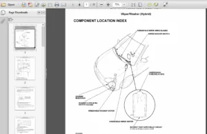
20-76 Opener Cable/Opener & Latch/Wiper & Washer 1026
20-53 Seats: Component Location Index 1003
20-86 Sub-frame 1036
20-17 Windsheild/Rear Window/Quarter Glass 967
21,22 Heater & Air Conditioning 1043
21 Heater 1045
22 Air Conditioning 1045
22-2 Special Tools 1046
22-3 Illustrated Index 1047
22-5 Wiring/Connector Locations 1049
22-6 Circuit Diagram 1050
22-8 Description 1052
22-9 Troubleshooting 1053
22-9 Symptom Chart 1053
22-10 Flowcharts 1054
22-33 Heater Control Panel: Input/Output Signals 1077
22-34 Heater Control Panel: Replacement/Overhaul 1078
22-35 Mode Control Motor: Replace/Test 1079
22-36 Recirculation Control Motor: Replace/Test 1080
22-37 Heater Fan Switch: Test 1081
22-37 A/C Thermostat: Test 1081
22-38 Relays: Test 1082
22-38 A/C Filter (99 model): Replace 1082
22-39 Blower Unit: Replace/Overhaul 1083
22-40/41 Evaporator: Replace/Overhaul 1084
22-42/44 Heater Unit: Replace/Overhaul 1085
22-45 Temperature Control Adjustment 1089
22-46 A/C Service Tips & Precautions 1090
22-47 A/C System Torque Specifications 1091
22-48 A/C System Service 1092
22-48 Performance Test 1092
22-50 Pressure Test Chart 1094
22-51 Recovery 1095
22-52 Evacuation 1096
22-53 Charging 1097
22-53 Leak Test 1097
22-54 Compressor 1098
22-54 Replacement 1098
22-56 Illustrated Index 1100
22-57 Clutch Inspection 1101
22-58 Clutch Overhaul 1102
22-60 Thermal Protector Replacement 1104
22-60 Relief Valve Replacement 1104
22-62 A/C Compressor Belt Adjustment 1106
22-63 Condenser Replacement 1107
23 Body Electrical 1108
23-1 SRS Warning 1109
23-2 Special Tools 1110
23-3 Troubleshooting 1111
23-3 Tips and Precautions 1111
23-5 Five-step Troubleshooting 1113
23-5 Wire Color Codes 1113
23-6 Relay and Control Unit Locations 1114
23-6 Engine Compartment 1114
23-7 Dashboard 1115
23-9 Door and Quarter Panel 1117
23-172 Accessory Socket 1280
Sec 15 Active Torque Transfer System (ATTS) 702
Sec 24 Airbags 1311
Sec 21 Air Conditioning 1045
Sec 4 Alternator 55
Sec 19 Anti-lock Brake System (ABS) 883
Sec 14 A/T Gear Position Indicator 494
Sec 14 Automatic Transmission System 494
23-49 Battery 1157
Sec 21 Blower Controls 1045
Sec 4 Charging System 55
23-149 Clock 1257
23-10 Connector Identification & Wire Harness Routing 1118
Sec 4 Cruise Control 55
Sec 10 Fan Controls 219
Sec 11 Fuel Pump 233
23-38 Fuses 1146
23-58 Gauge Assembly 1166
23-45 Ground Distribution 1153
23-159 Horns 1267
23-56 Ignition Switch 1164
Sec 4 Ignition System 55
23-195 Immobilizer System 1303
Sec 14 Interlock System 494
23-68 Lighting System 1176
23-73 Lights, Exterior 1181
23-82 Back-up Lights 1190
23-80 Brake Lights 1188
23-73 Daytime Running Lights 1181
23-76 Headlights 1184
23-81 High Mount Brake Light 1189
23-79 License Plate Light 1187
23-78 Side Marker Lights, Front 1186
23-79 Taillights 1187
23-85 Turn Signal Lights 1193
23-92 Lights, Interior 1200
23-94 Ceiling/Spotlight 1202
23-95 Courtesy Lights 1203
23-90 Dash Lights Brightness Control System 1198
23-97 Entry Light Control System 1205
23-95 Trunk Light 1203
23-143 Lights-on Reminder/Engine Oil Pressure 1251
23-169 Moon Roof 1277
23-100 Mulitplex Control System 1208
Sec 11 PGM-FI Control System 233
23-42 Power Distribution 1150
23-125 Power Door Locks 1233
23-174 Power Mirrors 1282
23-51 Power Relays 1159
23-112 Power Windows 1220
23-164 Rear Window Defogger 1272
23-146 Seat Belt Reminder 1254
23-183 Seat Heaters 1291
Sec 4 Spark Plugs 55
Sec 4 Starting System 55
23-150 Stereo Sound System 1258
Sec 24 Supplemental Restraint System (SRS) 1311
23-85 Turn Signal/Hazard Flasher System 1193
23-40 Under-dash Fuse/Relay Box 1148
23-38 Under-hood Fuse Relay Box 1146
23-65 Vehicle Speed Sensor 1173
23-186 Wiper/Washer 1294
24 Restraints 1311
24-2 Seat Belts 1312
24-2 Component Location Index 1312
24-3 Front Seat Belt 1313
24-5 Rear Seat Belt 1315
24-7 Inspection 1317
24-8 Child Seat Anchor Plate 1318
24-9 Supplemental Restraint System (SRS) 1319
24-10 Special Tools 1320
24-11 Component/Wiring Locations Index 1321
24-12 Description 1322
24-13 Circuit Diagram 1323
24-14 Precautions/Procedures 1324
24-14 General Precautions 1324
24-14 Airbag Handling & Storage 1324
24-15 SRS Unit Precautions 1325
24-15 Inspection After Deployment 1325
24-16 Wiring Precautions 1326
24-16 Backprobing Spring-loaded Lock Connectors 1326
24-17 Spring-loaded Lock Connector 1327
24-17 Spring-loaded Lock Connector w/ built-in short contacts 1327
24-18 Disconnecting the Airbag Connectors 1328
24-19 Steering-related Precautions 1329
24-20 Troubleshooting 1330
24-20 Self-diagnostic Procedures 1330
24-20 Reading the DTC 1330
24-22 Erasing the DTC Memory 1332
24-22 Troubleshooting Intermittent Failures 1332
24-23 Diagnostic Trouble Code (DTC) Chart 1333
24-25 SRS Indicator Light Wire Connections 1335
24-26 Flowcharts 1336
24-55 Driver’s Airbag Replacement 1365
24-57 Front Passenger’s Airbag Replacement 1367
24-59 Airbag Disposal 1369
24-61 Cable Reel Replacement 1371
24-65 SRS Unit Replacement 1375
Questions? Email us: [email protected]
PLEASE NOTE:
- This is the SAME manual used by the dealers to troubleshoot any faults in your vehicle. This can be yours in 2 minutes after the payment is made.
- Contact us at [email protected] should you have any queries before your purchase or that you need any other service / repair / parts operators manual.
S.V