Trusted Business
Verified & Licensed
Virus Free Files
100% Safe Downloads
Secure Payment
SSL Protected
Instant Delivery
Available Immediately
1997 NISSAN 240SX S14 Series Service Manual PDF DOWNLOAD
$35.95
1997 NISSAN 240SX S14 Series Service Manual PDF DOWNLOAD
Instant PDF Download
Available immediately
Save to Your Device
Download & keep forever
Antivirus Scanned
100% virus-free
Trusted Worldwide
175,000+ customers
Description
1997 NISSAN 240SX S14 Series Service Manual PDF DOWNLOAD
FILE DETAILS:
1997 NISSAN 240SX S14 Series Service Manual PDF DOWNLOAD
Language : English
Pages : 1295
Downloadable :Yes
File Type : PDF
IMAGES PREVIEW OF THE MANUAL:
TABLE OF CONTENTS:
1997 NISSAN 240SX S14 Series Service Manual PDF DOWNLOAD
foreword 1
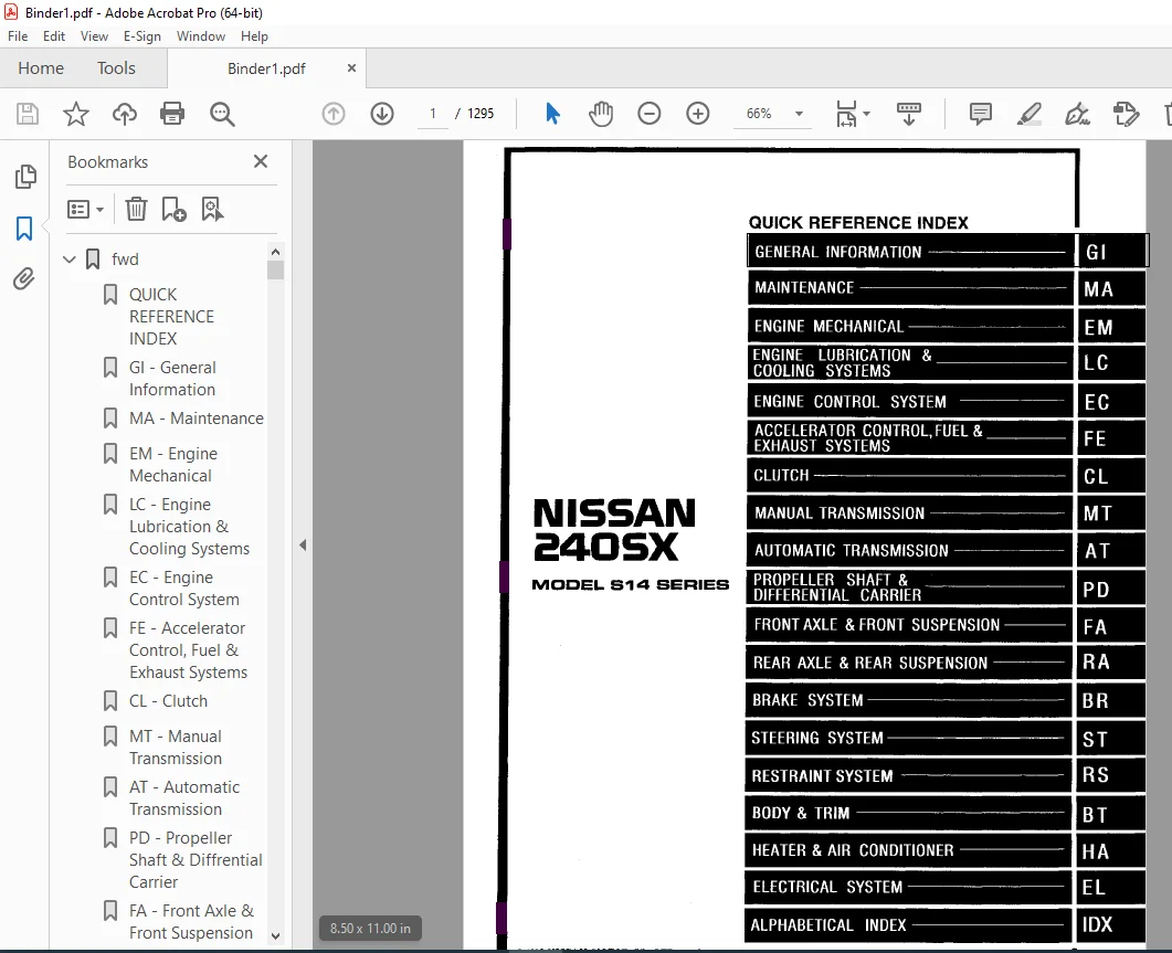
QUICK REFERENCE INDEX 1
GI – General Information 0
MA – Maintenance 0
EM – Engine Mechanical 0
LC – Engine Lubrication & Cooling Systems 0
EC – Engine Control System 0
FE – Accelerator Control, Fuel & Exhaust Systems 0
CL – Clutch 0
MT – Manual Transmission 0
AT – Automatic Transmission 0
PD – Propeller Shaft & Diffrential Carrier 0
FA – Front Axle & Front Suspension 0
RA – Rear Axle & Rear Suspension 0
BR – Brake System 0
ST – Steering System 0
RS – Restraint System 0
BT – Body & Trim 0
HA – Heater & Air Conditioner 0
EL – Electrical System 0
IDX – Alphabetical Index 1
Foldout 0
Comment Sheet 3
Quick Reference Chart 4
GST Mode 6 – Test Value & Test Limit Chart 5
at 6
QUICK REFERENCE INDEX 0
TABLE OF CONTENTS 6
PREPARATION AND PRECAUTIONS 8
Special Service Tools 8
Supplemental Restraint System (SRS) ” AIR BAG” 9
Precautions for On Board Diagnostic (OBD) System of A/T and Engine 9
Precautions 10
Service Notice or Precautions 11
OVERALL SYSTEM 12
A/T Electrical Parts Location 12
Circuit Diagram 13
Wiring Diagram – AT – 14
Cross-sectional View 19
Hydraulic Control Circuit 20
Shift Mechanism 21
Control System 23
ON BOARD DIAGNOSTIC SYSTEM DESCRIPTION 25
Introduction 25
One or Two Trip detection Logic 25
Diagnostic Trouble Code (DTC) 25
Self-diagnosis 27
Diagnosis by CONSULT 32
TROUBLE DIAGNOSIS – Introduction 35
Introduction 35
Dignostic Worksheet 36
Work Flow 39
TROUBLE DIAGNOSIS – Basic Inspection 40
A/T Fluid Check 40
Road Test 40
Shift Schedule 50
TROUBLE DIAGNOSIS – General Description 52
Diagnostic Trouble Code (DTC) Chart 52
Symptom Chart 54
A/T Control Unit Terminals and Reference Value 57
DTC P0705, Inhibitor, Overdrive Control Throttle Position Switches 61
DTC P0710, A/T Fluid Temperature Sensor Circuit and A/T Control Unit Power Source 67
DTC P0720, Vehicle Speed Sensor-A/T (Revolution sensor) 70
DTC P0725, Engine Speed Signal 72
DTC P0731, Improper Shifting to 1st Gear Position 74
DTC P0732, Improper Shifting to 2nd Gear Postion 77
DTC P0733, Improper Shifting to 3rd Gear Position 79
DTC P0734, Improper Shifting to 4th Gear Postion 81
DTC P0740, Torque Converter Clutch Solenoid Valve 86
DTC P0744, Improper Lock-up Operation 89
DTC P0745, Line Pressure Solenoid Valve 94
DTC P0750, Shift Solenoid Valve A 97
DTC P0755, Shift Solenoid Valve B 100
DTC P1705, Throttle Position Sensor 103
DTC P1760, Overrun Clutch Solenoid Valve 105
TROUBLE DIAGNOSIS FOR VHCL SPEED SEN-MTR 108
Vehicle Speed Sensor-MTR 108
DIAGNOSTIC PROCEDURES FOR SYMPTOMS 110
1 O/D OFF Indicator Lamp Does Not Come On 110
2 Engine Cannot Be Started In “P” and “N” Position 111
3 In “P” Postion, Vehicle Moves Forward Or Backward When Pushed 111
4 In “N” Position, Vehicle Moves 112
5 Large Shock “N” – “R” Postion 113
6 Vehicle Does Not Creep Backward In “R” Postion 114
7 Vehicle Does Not Creep Forward In “D”, “2” Or “1” Postion 115
8 Vehicle Cannot Be Started From D1 116
9 A/T Does Not Shift: D1 – D2 Or Does Not Kickdown: D4 – D2 117
10 A/T Does Not Shift: D2 – D3 118
11 A/T Does Not Shift: D3 – D4 119
12 A/T Does Not Perform Lock-up 120
13 A/T Does Not Hold Lock-up Condition 121
14 Lock-up Is Not Released 121
15 Engine Speed Does Not Return To Idle (Light Braking D4 – D3 122
16 Vehicle Does Not Start From D1 123
17 A/T Does Not Shift: D4 – D3, When Overdrive Control Switch “ON” – “OFF” 123
18 A/T Does Not Shift: D3 – 22, When Selector Lever “D” – “2” Position 124
19 A/T Does Not Shift: 22 – 11, When Selector Lever “2” – “1” Postion 124
20 Vehicle Does Not Decelerate By Engine Brake 125
TROUBLE DIAGNOSES 126
Final Check 126
TROUBLE DIAGNOSES – A/T Shift Lock System 131
Description 131
Wiring diagram – SHIFT – 132
Diagnostic Procedure 133
Key Interlock Cable 135
Component Check 136
ON-VEHICLE SERVICE 138
Control Valve Assembly and Accumulators 138
Revolution Sensor Replacement 138
Rear Oil Seal Replacement 139
Parking Components Inspection 139
Inhibitor Switch Adjustment 140
Manual Control Linkage Adjustment 140
REMOVAL AND INSTALLATION 141
Removal 141
Installation 143
MAJOR OVERHAUL 144
Oil Channel 146
Locations of Needle Bearings, Thrust Washers and Snap Rings 147
DISASSEMBLY 148
Disassembly 148
REPAIR FOR COMPONENT PARTS 159
Oil Pump 159
Control Valve Assembly 163
Control Valve Upper Body 169
Control Valve Lower Body 174
Reverse Clutch 176
High Clutch 180
Forward and Overrun Clutches 182
Low & Reverse Brake 186
Forward Clutch Drum Assembly 190
Rear Internal Gear and Forward Clutch Hub 192
Band Servo Piston Assembly 195
Parking Pawl Components 199
ASSEMBLY 201
Assembly (1) 201
Adjustment 205
Assembly (2) 209
SERVICE DATA AND SPECIFICATIONS (SDS) 219
General Specifications 219
Specifications and Adjustment 219
br 223
QUICK REFERENCE INDEX 0
TABLE OF CONTENTS 223
PRECAUTIONS AND PREPARATION 225
Precautions 225
Commercial Service Tools 225
BRAKE HYDRAULIC LINE/CONTROL VALVE 226
Brake Hydraulic Line 226
Proportioning Valve 227
CHECK AND ADJUSTMENT 228
Checking Brake Fluid Level 228
Checking Brake Line 228
Changing Brake Fluid 228
Bleeding Brake System 229
BRAKE PEDAL AND BRACKET 230
Removal and Installation 230
Inspection 230
Adjustment 230
MASTER CYLINDER 231
Removal 231
Disassembly 232
Inspection 232
Assembly 232
Installation 233
BRAKE BOOSTER/VACUUM HOSE 234
Brake Booster 234
Vacuum Hose 235
FRONT DISC BRAKE 236
Pad Replacement 236
Removal 238
Disassembly 238
Inspection – Caliper 238
Inspection – Rotor 239
Assembly 239
Installation 239
REAR DISC BRAKE 240
Pad Replacement 240
Removal 242
Disassembly 242
Inspection – Caliper 243
Inspection – Rotor 244
Assembly 244
Installation 246
PARKING BRAKE CONTROL 247
Removal and Installation 247
Inspection 248
Adjustment 248
ANTI-LOCK BRAKE SYSTEM 249
Purpose 249
Operation 249
ABS Hydraulic Circuit 249
System Components 250
System Description 250
Removal and Installation 252
TROUBLE DIAGNOSES 255
How to Perform Trouble Diagnoses for Quick and Accurate Repair 255
Preliminary Check 256
Component Parts and Harness Connector Location 257
Circuit Diagram for Quick Pinpoint Check 258
Wiring Diagram – ABS – 259
Self-diagnosis 264
CONSULT 267
CONSULT Inspection Procedure 268
Ground Circuit Check 273
TROUBLE DIAGNOSES FOR SELF-DIAGNOSTIC ITEMS 274
Diagnostic Procedure 1 (Wheel sensor or rotor) 274
Diagnostic Procedure 2 (ABS actuator solenoid valve) 276
Diagnostic Procedure 3 (Solenoid valve relay) 277
Diagnostic Procedure 4 (Motor relay or motor) 280
Diagnostic Procedure 5 (Low voltage) 283
Diagnostic Procedure 6 (Control unit) 284
TROUBLE DIAGNOSES FOR SYMPTOMS 285
Diagnostic Procedure 7 (ABS works frequently ) 285
Diagnostic Procedure 8 (Unexpected pedal action) 286
Diagnostic Procedure 9 (Long stopping distance) 286
Diagnostic Procedure 10 (ABS does not work ) 287
Diagnostic Procedure 11 (Pedal vibration and noise) 287
Diagnostic Procedure 12 (Warning lamp does not come on when ignition switch is turned on ) 288
Diagnostic Procedure 13 (Warning lamp stays on when ignition switch is turned on ) 290
Electrical Component Inspection 293
SERVICE DATA AND SPECIFICATIONS (SDS) 295
General Specifications 295
Inspection and Adjustment 295
bt 296
QUICK REFERENCE INDEX 0
TABLE OF CONTENTS 296
PRECAUTIONS 297
Service Notice 297
Supplemental Restraint System (SRS) “AIR BAG” 297
GENERAL SERVICING 298
Clip and Fastener 298
BODY END 301
Body Front End 301
Body Rear End and Opener 304
DOOR 306
Door Glass Fitting Adjustment 307
INSTRUMENT PANEL 311
INTERIOR TRIM 314
Side and Floor Trim 314
Door Trim 316
Roof Trim 317
Trunk Room Trim 318
EXTERIOR 319
SEAT 326
Front Seat 326
Rear Seat 328
SUNROOF 329
WINDSHIELD AND WINDOWS 333
Windshield and Rear Window 333
Side Window 334
MIRROR 335
Door Mirror 335
BODY ALIGNMENT 336
Engine Compartment 336
Underbody 338
cl 340
QUICK REFERENCE INDEX 0
TABLE OF CONTENTS 340
PRECAUTIONS AND PREPARATION 341
Precautions 341
Special Service Tools 341
Commercial Service Tools 341
CLUTCH SYSTEM 342
INSPECTION AND ADJUSTMENT 343
Adjusting Clutch Pedal 343
Bleeding Procedure 344
HYDRAULIC CLUTCH CONTROL 345
Clutch Master Cylinder 345
Operating Cylinder 346
CLUTCH RELEASE MECHANISM 347
CLUTCH DISC AND CLUTCH COVER 349
Clutch Disc 349
Clutch Cover and Flywheel 350
SERVICE DATA AND SPECIFICATIONS (SDS) 351
General Specifications 351
Inspection and Adjustment 351
ec 352
QUICK REFERENCE INDEX 0
TABLE OF CONTENTS 352
DIAGNOSTIC TROUBLE CODE INDEX 354
Alphabetical & P No Index for DTC 354
PRECAUTIONS AND PREPARATION 356
Special Service Tools 356
Commercial Service Tool 356
Supplemental Restraint System (SRS) “AIR BAG” 357
Precautions for On Board Diagnostic (OBD) System of Engine and A/T 357
Engine Fuel & Emission Control System 358
Precautions 359
ENGINE AND EMISSION CONTROL OVERALL SYSTEM 361
Circuit Diagram 361
System Diagram 362
ECCS Component Parts Location 363
Vacuum Hose Drawing 365
System Chart 366
ENGINE AND EMISSION BASIC CONTROL SYSTEM DESCRIPTION 367
Multiport Fuel Injection (MFI) System 367
Distributor Ignition (DI) System 369
Air conditioning Cut Control 370
Fuel Cut Control (at no load & high engine speed) 371
EVAPORATIVE EMISSION SYSTEM 372
Description 372
Inspection 372
Evaporative Emission Line Drawing 374
POSITIVE CRANKCASE VENTILATION 376
Description 376
Inspection 376
BASIC SERVICE PROCEDURE 377
Fuel Pressure Release 377
Fuel Pressure Check 377
Injector Removal and Installation 378
Idle Speed/Ignition Timing/Idle Mixture Ratio Adjustment 379
ON BOARD DIAGNOSTIC SYSTEM DESCRIPTION 385
Introduction 385
Two Trip Detection Logic 385
Emission-related Diagnostic Information 386
Malfunction Indicator Lamp (MIL) 396
OBD System Operation Chart 399
CONSULT 404
Generic Scan Tool (GST) 417
TROUBLE DIAGNOSIS – Introduction 419
Introduction 419
Diagnostic Worksheet 419
TROUBLE DIAGNOSIS – Work Flow 421
Work Flow 421
Description for Work Flow 422
TROUBLE DIAGNOSIS – Basic Inspection 423
Basic Inspection 423
TROUBLE DIAGNOSIS – General Description 426
Diagnostic Trouble Code (DTC) Inspection Priority Chart 426
Fail-Safe Chart 427
Symptom Matrix Chart 428
CONSULT Reference Value in Data Monitor Mode 431
Major Sensor Reference Graph in Data Monitor Mode 434
ECM Terminals and Reference Value 436
TROUBLE DIAGNOSIS FOR POWER SUPPLY 443
Main Power Supply and Ground Circuit 443
DTC P0100, Mass Air Flow Sensor (MAFS) 446
DTC P0105, Absolute Pressure Sensor 451
DTC P0110, Intake Air Temperature Sensor 458
DTC P0115, Engine Coolant Temperature Sensor (ECTS) 463
DTC P0120, Throttle Position Sensor 468
DTC P0125, Engine Coolant Temperature (ECT) Sensor 473
DTC P0130, Front Heated Oxygen Sensor (Front HO2S) 478
Closed Loop Control 483
DTC P0135, Front Heated Oxygen Sensor Heater 484
DTC P0136, Rear Heated Oxygen Sensor (Rear HO2S) 487
DTC P0141, Rear Heated Oxygen Sensor Heater 491
DTC P0171, Fuel Injection system Function (Lean side) 495
DTC P0172, Fuel Injection System Function (Rich side) 500
DTC P0180, Tank Fuel Temperature Sensor 505
DTC P0300 – P0304, No 4 – 1 Cylinder Misfire, Multiple Cylinder Misfire 509
DTC P0325, Knock Sensor (KS) 513
DTC P0335, Crankshaft Position Sensor (CKPS) (OBD) 516
DTC P0340, Camshaft Position Sensor (CMPS) 520
DTC P0400, EGR Function 524
DTC P0402, EGRC-BPT Valve Function 532
DTC P0420, Three Way Catalyst Function 534
DTC P0440, Evaporative Emission (EVAP) Control System (Small Leak) 537
DTC P0443, Evaporative Emission (EVAP) Canister Purge Control Valve/Solenoid Valve 547
DTC P0446, Evaporative Emission (EVAP) Canister Vent Control Valve 555
DTC P0450, Evaporative Emission (EVAP) Control System Pressure Sensor 561
DTC P0500, Vehicle Speed Sensor (VSS) 565
DTC P0505, Idle Air Control Valve (IACV) – Auxiliary Air Control (AAC) Valve 569
DTC P0510, Closed Throttle Position Switch 574
DTC P0600, A/T Control 578
DTC P0605, Engine Control Module (ECM)-ECCS Control Module 581
DTC P0705, Park/Neutral Position Switch 583
DTC P1105, Mainfold Absolute Pressure (MAP)/Barometric Pressure (BARO) Switch Solenoid Valve 588
DTC P1320, Ignition Signal 594
DTC P1336, Crankshaft Position Sensor (CKPS) (OBD) (COG) 599
DTC P1400, EGRC-Solenoid Valve 603
DTC P1401, EGR Temperature Sensor 607
DTC P1441, Vacuum Cut Valve Bypass Valve 612
DTC P1445, Evaporative Emission (EVAP) Canister Purge Volume Control Valve 617
DTC P1447, Evaporative Emission (EVAP) Control System Purge Flow Monitoring 623
DTC P1605, A/T Diagnosis Communication Line 630
DTC P1900, Overheat 633
TROBLE DIAGNOSIS FOR NON-DETECTABLE ITEMS 645
Injector 645
Start Signal 648
Fuel Pump 650
Power Steering Oil Pressure Switch 655
IACV-Air Regulator 658
IACV-FICD Solenoid Valve 661
5th Position Switch 665
Electrical Load Signal 667
MIL & Data Link Connectors 669
SERVICE DATA AND SPECIFICATIONS (SDS) 670
General Specifications 670
Inspection and Adjustment 670
el 672
QUICK REFERENCE INDEX 0
TABLE OF CONTENTS 672
PRECAUTIONS 675
Supplemental Restraint System (SRS) “AIR BAG” 675
HARNESS CONNECTOR 676
Description 676
STANDARDIZED RELAY 677
Description 677
POWER SUPPLY ROUTING 679
Schematic 679
Wiring Diagram – POWER – 681
Fuse 689
Fusible Link 689
Circuit Breaker Inspection 689
GROUND DISTRIBUTION 690
BATTERY 693
How to Handle Battery 693
Service Data and Specifications (SDS) 696
STARTING SYSTEM 697
System Description 697
Wiring Diagram – START – 699
Construction 701
Removal and Installation 701
Pinion/Clutch Check 702
Service Data and Specifications (SDS) 702
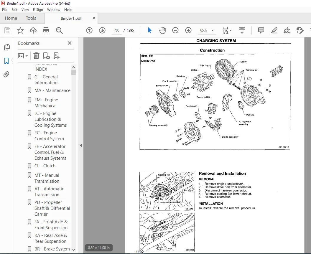
CHARGING SYSTEM 703
System Description 703
Wiring Diagram – CHARGE – 704
Construction 705
Removal and Installation 705
Trouble Diagnoses 706
Service Data and Specifications (SDS) 707
COMBINATION SWITCH 708
Combination Switch/Check 708
Replacement 709
Steering Switch/Check 710
HEADLAMP 711
System Description (For USA) 711
Wiring Diagram (For USA) – H/LAMP – 712
Ttouble Diagnoses (For USA) 713
System Description (Daytime light system for Canada) 714
Operation (Daytime light system for Canada) 715
Schematic (Daytime light system for Canada) 716
Wiring Diagram (Daytime light system for Canada) – DTRL – 717
Trouble Diagnoses (Daytime light system for Canada) 720
Bulb Replacement 722
Aiming Adjustment 723
EXTERIOR LAMP 724
Parking, License, Tail and Stop Lamps/Wiring Diagram – TAIL/L – 724
Back-up Lamp/Wiring Diagram – BACK/L – 726
Front Fog Lamp/System Description 728
Front Fog Lamp/Wiring Diagram – F/FOG – 729
Front Fog Lamp Aiming Adjustment 730
Turn Signal and Hazard Warning Lamps/System Description 731
Turn Signal and Hazard Warning Lamps/Schematic 733
Turn Signal and Hazard Warning Lamps/Wiring Diagram – TURN – 734
Turn signal and Hazard Warning Lamps/Trouble Diagnoses 737
Combination Flasher Unit Check 737
Bulb Specifications 738
INTERIOR LAMP 739
Illumination/System Description 739
Illumination/Schmatic 740
Illumination/Wiring Diagram – ILL – 741
Interior, Spot and Trunk Room Lamps/System Description 744
Bulb Specifications 744
Interior, Spot and Trunk Room Lamps/Wiring Diagram – INT/L – 745
METER AND GAUGES 747
System Description 747
Combination Meter 748
Speedometer, Tachometer, Temp and Fuel Gauges/Wiring Diagram – METER – 749
Inspection/Fuel Gauge and/or Water Temperature Gauge 750
Inspection/Trachometer 751
Inspection/Speedometer and Vehicle Speed Sensor 752
Fuel Tank Gauge Unit Check 753
Thermal Transmitter Check 753
Vehicle Speed Sensor Signal Check 753
WARNING LAMPS 754
Warning Lamps/Schematic 754
Warning Lamps/Wiring Diagram – WARN – 755
Fuel Warning Lamp Sensor Check 758
Oil Pressure Switch Check 758
Diode Check 758
WARNING BUZZER 759
Warning Buzzer/System Description 759
Warning Buzzer/Wiring Diagram – BUZZER – 761
Trouble Diagnoses 763
WIPER AND WASHER 768
System Description 768
Front Wiper and Washer/Wiring Diagram – WIPER – 770
Trouble Diagnoses 773
Wiper Installation and Adjustment 775
Washer Nozzle Adjustment 775
Washer Tube Layout 776
Wiper Linkage 776
HORN, CIGARETTE LIGHTER AND CLOCK 777
Wiring Diagram – HORN – 777
REAR WINDOW DEFOGGER 779
System Description 779
Wiring Diagram – DEF – 780
Trouble Diagnoses 782
Filament Check 784
Filament Repair 785
AUDIO AND POWER ANTENNA 787
Audio/System Description 787
Audio (4-speaker models)/Schematic 788
Audio (4-speaker models)/Wiring Diagram – AUDIO – 789
Audio (6-speaker models)/Schematic 791
Audio (6-speaker models)/Wiring Diagram – AUDIO – 792
Power Antenna/System Description 795
Power Antenna/Wiring Diagram – P/ANT – 796
Trouble Diagnoses 797
Location of Antenna 798
Antenna Rod Replacement 798
Window Antenna Repair 799
POWER SUNROOF 801
Wiring Diagram – SROOF – 801
POWER DOOR MIRROR 802
Wiring Diagram – MIRROR – 802
AUTOMATIC SPEED CONTROL DEVICE (ASCD) 804
Component Parts and Harness Connector Location 804
System Description 805
Schematic 807
Wiring Diagram – ASCD – 808
Trouble Diagnoses 813
POWER WINDOW 826
System Description 826
Wiring Diagram – WINDOW – 828
Trouble Diagnoses 830
POWER DOOR LOCK 831
System Description 831
Wiring Diagram – D/LOCK – 832
Trouble Diagnoses 834
MULTI-REMOTE CONTROL SYSTEM 837
System Description 837
Schematic 839
Wiring Diagram – MULTI – 840
Trouble Diagnoses 843
Replacing Remote Controller or Control Unit 850
THEFT WARNING SYSTEM 851
Component Parts and Harness Connector Location 851
System Description 852
Schematic 855
Wiring Diagram – THEFT – 856
Trouble Diagnoses 863
SMART ENTRANCE CONTROL UNIT 877
Description 877
Input/Output Operation Signal 878
Schematic 879
LOCATION OF ELECTRICAL UNITS 881
Engine Compartment 881
Passenger Compartment 882
HARNESS LAYOUT 884
Outline 884
Main Harness 885
Engine Room Harness 887
Engine Harness 890
Engine control Harness 891
Body Harness and Tail Harness 893
Room Lamp 895
Air Bag Harness 896
Door Harness LH 897
Door Harness RH 897
SUPER MULTIPLE JUNCTION (SMJ) 0
Disconnecting and Connecting 0
Terminal Arrangement 1
ELECTRICAL UNITS 2
Terminal Arrangement 2
em 898
QUICK REFERENCE INDEX 0
TABLE OF CONTENTS 898
PRECAUTIONS 899
Parts Requiring Angular Tightening 899
Liquid Gasket Application Procedure 899
PREPARATION 900
Special Service Tools 900
Commercial Service Tools 903
OUTER COMPONENT PARTS 904
COMPRESSION PRESSURE 906
Measurement of Compression Pressure 906
OIL PAN 907
Removal 907
Installation 908
TIMING CHAIN 909
Removal 911
Inspection 914
Installation 914
OIL SEAL REPLACEMENT 918
CYLINDER HEAD 920
Removal and Installation 921
Disassembly 921
Inspection 922
Assembly 927
Valve Clearance 927
ENGINE REMOVAL 930
Removal 931
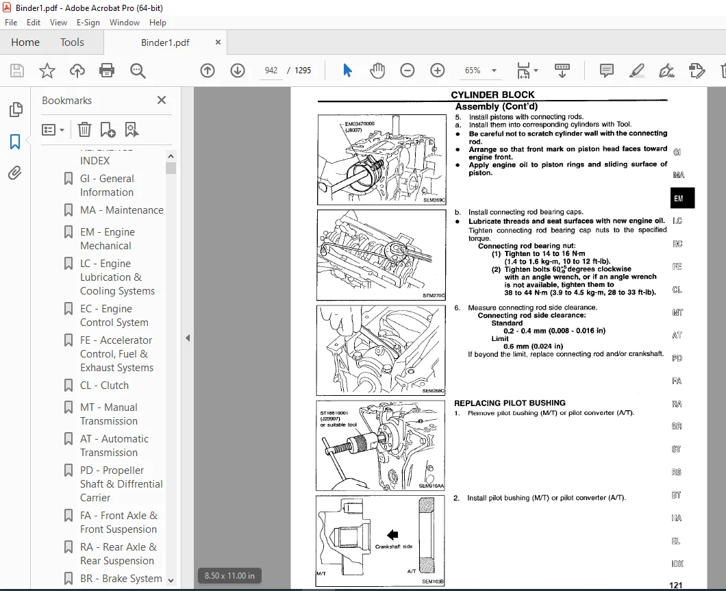
CYLINDER BLOCK 932
Disassembly 933
Inspection 934
Assembly 940
SERVICE DATA AND SPECIFICATIONS (SDS) 943
General Specifications 943
Inspection and Adjustment 943
fa 951
QUICK REFERENCE INDEX 0
TABLE OF CONTENTS 951
PRECAUTIONS AND PREPARATION 952
Precautions 952
Special Service Tools 952
Commercial Service Tools 953
FRONT SUSPENSION SYSTEM 954
ON-VEHICLE SERVICE 955
Front Axle and Front Suspension Parts 955
Front Wheel Bearing 955
Front Wheel Alignment 956
FRONT AXLE 958
Wheel Hub and Knuckie 958
ABS Sensor Rotor 960
Baffle Plate 961
FRONT SUSPENSION 962
Coil Spring and Strut Assembly 963
Tension Rod and Stabilizer Bar 964
Transverse Link and Lower Ball Joint 965
SERVICE DATA AND SPECIFICATIONS (SDS) 966
General Specifications 966
Inspection and Adjustment 967
fe 968
QUICK REFERENCE INDEX 0
TABLE OF CONTENTS 968
PREPARATION/ACCELERATOR CONTROL SYSTEM 969
Special Service Tool 969
Accelerator Control System 969
Adjusting Accelerator Wire 969
FUEL SYSTEM 970
Fuel Tank 970
Fuel Pump and Gauge 972
EXHAUST SYSTEM 974
foldout 975
QUICK REFERENCE INDEX 0
ELECTRICAL SYSTEM 0
SUPER MULTIPLE JUNCTION (SMJ) 975
Disconnecting and Connecting 975
Terminal Arrangement 976
ELECTRICAL UNITS 977
Terminal Arrangement 977
gi 978
QUICK REFERENCE INDEX 0
TABLE OF CONTENTS 978
PRECAUTION 979
Precautions for Supplemental Restraint System (SRS) “AIR BAG” 979
General Precautions 979
Precautions for Multiport Fuel injection System or ECCS Engine 981
Precautions for Three Way Catalyst 982
Engine Oils 982
Precatuions for Fuel 983
Precautions for Air Conditioning 983
HOW TO USE THIS MANUAL 984
HOW TO READ WIRING DIAGRAMS 986
Sample/Wiring Diagram – EXAMPL – 986
Description 988
Wiring Diagram Codes (Cell Codes) 995
HOW TO PERFORM EFFICIENT DIAGNOSIS FOR AN ELECTRICAL INCIDENT 996
Work Flow 996
Incident Simulation Tests 997
Circuit Inspection 1001
HOW TO FOLLOW FLOW CHART IN TROUBLE DIAGNOSES 1008
CONSULT CHECKING SYSTEM 1011
Function and System Application 1011
Lithium Battery Replacement 1011
Checking Equipment 1011
IDENTIFICATION INFORMATION 1012
Model Variation 1012
Identification Number 1013
Dimensions 1015
Wheels and Tires 1015
LIFTING POINTS AND TOW TRUCK TOWING 1016
Preparation 1016
Board-on Lift 1016
Garage Jack and Safety Stand 1017
2-pole Lift 1018
Tow Truck Towing 1018
TIGHTENING TORQUE OF STANDARD BOLTS 1020
SAE J1930 TERMINOLOGY LIST 1021
SAE J1930 Terminology List 1021
ha 1025
QUICK REFERENCE INDEX 0
TABLE OF CONTENTS 1025
PRECAUTIONS AND PREPARATION 1026
Supplemental Restraint System (SRS) “AIR BAG” 1026
Precautions for Working with HFC-134a (R-134a) 1026
General Refrigerant Precautions 1026
Precautions for Refrigerant Connection 1027
Precautions for Servicing Compressor 1030
Special Service Tools 1030
HFC-134a (R-134a) Service Tools and Equipment 1031
Precautions for Service Equipment 1033
DESCRIPTION 1035
Refrigeration Cycle 1035
Component Layout 1036
Discharge Air Flow 1037
Control Operation 1038
V-6 Variable Displacement Compressor 1039
TROUBLE DIAGNOSES 1045
How to Perform Trouble diagnoses for Quick and Accurate Repair 1045
Operational Check 1046
Symptom Chart 1048
Preliminary Check 1050
Performance Test Diagnoses 1056
Performance Chart 1058
Trouble Diagnoses for Abnormal Pressure 1059
Harness Layout 1062
Circuit Diagram 1064
Wiring Diagram – A/C – 1065
Main Power Supply and Ground Circuit Check 1071
Diagnostic Procedure 1 1072
Diagnostic Procedure 2 1074
Diagnostic Procedure 3 1076
Diagnostic Procedure 4 1077
Diagnostic Procedure 5 1079
Diagnostic Procedure 6 1080
Electrical Components Inspection 1083
Control Linkage Adjustment 1085
SERVICE PROCEDURES 1087
HFC-134a (R-134a) Service Procedure 1087
Maintenance of Lubricant Quantity In Compressor 1089
Refrigerant Lines 1091
Checking Refrigerant Leaks 1092
Compressor Mounting 1094
Belt Tension 1094
Fast Idle Control Device (FICD) 1094
Push Control Unit 1095
Compressor 1096
Compressor Clutch 1096
SERVICE DATA AND SPECIFICATIONS (SDS) 1100
General Specifications 1100
Inspection and Adjustment 1100
idx 1101
QUICK REFERENCE INDEX 0
lc 1108
QUICK REFERENCE INDEX 0
TABLE OF CONTENTS 1108
PRECAUTION AND PREPARATION 1109
Liquid Gasket Application Procedure 1109
Special Serive Tools 1109
ENGINE LUBRICATION SYSTEM 1111
Lubrication Circuit 1111
Oil Pressure Check 1111
Oil Pump 1112
ENGINE COOLING SYSTEM 1114
Cooling Circuit 1114
System Check 1114
Water Pump 1115
Thermostat 1116
Radiator 1117
Cooling Fan (Crankshaft driven) 1120
Cooling Fan Control System 1120
Overheating Cause Analysis 1121
SERVICE DATA AND SPECIFICATIONS (SDS) 1122
Engine Lubrication System 1122
Engine Cooling System 1122
ma 1123
QUICK REFERENCE INDEX 0
TABLE OF CONTENTS 1123
PRECAUTIONS 1124
Supplemental Restraint system (SRS) “AIR BAG” 1124
GENERAL MAINTENANCE 1125
PERIODIC MAINTENANCE 1127
Schedule 1 1128
Schedule 2 1129
RECOMMENDED FLUIDS AND LUBRICANTS 1130
Fluids and Lubricants 1130
SAE Viscosity Number 1130
Anti-freeze Coolant Mixture Ratio 1131
ENGINE MAINTENANCE 1132
Checking Drive Belts 1132
Changing Engine Coolant 1133
Checking Fuel Lines 1134
Changing Fuel Filter 1135
Changing Air Cleaner Filter 1135
Changing Engine Oil 1136
Changing Oil Filter 1136
Changing Spark Plugs 1137
Checking EVAP Vapor Purge Lines 1138
CHASSIS AND BODY MAINTENANCE 1139
Checking Exhaust System 1139
Checking Clutch Fluid Level and Leaks 1139
Checking M/T Oil 1139
Changing M/T Oil 1139
Checking A/T Fluid 1140
Changing A/T Fluid 1140
Checking Differential Gear Oil 1141
Changing Differential Gear Oil 1141
Balancing Wheels 1141
Tire Rotation 1141
Checking Brake Fluid Level and Leaks 1141
Checking Brake Lines and Cables 1142
Checking Disc Brake 1142
Checking Steering Gear and Linkage 1142
Checking Power Steering Fluid and Lines 1143
Lubricating Locks, Hinges and Hood Latches 1144
Checking Seat Belts, Buckles, Retractors, Anchors and Adjusters 1144
SERVICE DATA AND SPECIFICATIONS (SDS) 1145
Engine Maintenance 1145
Chassis and Body Maintenance 1145
mt 1146
QUICK REFERENCE INDEX 0
TABLE OF CONTENTS 1146
PREPARATION 1146
Special Service Tools 1147
Commercial Service Tools 1149
DESCRIPTION 1150
Cross-sectional View 1150
ON-VEHICLE SERVICE 1151
Replacing Rear Oil Seal 1151
Position Switch Check 1151
REMOVAL AND INSTALLATION 1152
Removal 1152
Installation 1153
MAJOR OVERHAUL 1154
Case Components 1154
Gear Components 1155
Shift Control Components 1156
DISASSEMBLY 1157
Case Components 1157
Shift Control Components 1158
Gear Components 1158
INSPECTION 1161
Shift Control Components 1161
Gear Components 1161
ASSEMBLY 1163
Gear Components 1163
Shift Control Components 1169
Case Components 1170
SERVICE DATA AND SPECIFICATIONS (SDS) 1173
General Specifications 1173
Inspection and Adjustment 1173
pd 1175
QUICK REFERENCE INDEX 0
TABLE OF CONTENTS 1175
PREPARATION 1176
Special Service Tools 1176
Commercial Service Tool 1178
PROPELLER SHAFT 1179
On-vehicle Service 1180
Removal 1180
Installation 1180
Inspection 1181
Disassembly 1182
Assembly 1182
FINAL DRIVE 1183
ON-VEHICLE SERVICE/REMOVAL AND INSTALLATION 1183
Front Oil Seal Replacement 1183
Side Oil Seal Replacement 1183
Removal 1184
Installation 1185
FINAL DRIVE 1186
DISASSEMBLY 1188
Pre-inspection 1188
Differential Carrier 1188
Differential Case 1190
INSPECTION 1192
Ring Gear and Drive Pinion 1192
Bearing 1192
Differential Case Assembly 1192
ADJUSTMENT 1193
Side Bearing Preload 1193
Pinion Gear Height and Pinion Bearing Preload 1194
Tooth Contact 1199
ASSEMBLY 1200
Differential Case 1200
Differential Carrier 1202
SERVICE DATA AND SPECIFICATIONS (SDS) 1206
Propeller Shaft 1206
Final Drive 1206
ra 1208
QUICK REFERENCE INDEX 0
TABLE OF CONTENTS 1208
PRECAUTIONS AND PREPARATION 1209
Precautions 1209
Special Service Tools 1209
Commercial Service Tools 1210
REAR SUSPENSION SYSTEM 1211
ON-VEHICLE SERVICE 1212
Rear Axle and Rear Suspension Parts 1212
Rear Wheel Bearing 1212
Rear Wheel Alignment 1212
Drive Shaft 1214
REAR AXLE 1215
Wheel Hub and Axle Housing 1215
Drive Shaft 1219
REAR SUSPENSION 1225
Removal and Installation 1226
Coil Spring and Shock Absorber 1227
Multi-link and Lower Ball Joint 1228
Stabilizer Bar 1229
SERVICE DATA AND SPECIFICATIONS (SDS) 1230
General Specifications 1230
Inspection and Adjustment 1231
rs 1232
QUICK REFRERENCE INDEX 0
TABLE OF CONTENTS 1232
PRECAUTIONS 1233
Supplemental Restraint System (SRS) “AIR BAG” 1233
SEAT BELTS 1234
Front Seat Belt 1234
Rear Seat Belt 1235
SUPPLEMENTAL RESTRAINT SYSTEM (SRS) 1236
Precautions for SRS “Air Bag” Service 1236
Special Service Tools 1236
Description 1237
SRS Component Parts Location 1237
Maintenance Items 1238
Removal and Installation–Diagnosis Sensor Unit 1239
Removal – Air Bag Module and Spiral Cable 1240
Removal – Front Passenger Air Bag Module 1241
Installation – Air Bag Module and Spiral Cable 1242
Installation – Front Passenger Air Bag Module 1243
Disposal of Air Bag Module 1244
TROUBLE DIAGNOSES – Supplemental Restraint System (SRS) 1248
How to Perform Trouble Diagnoses for Quick and Accurate Repair 1248
Schematic 1250
Wiring diagram – SRS – 1251
Self-diagnosis 1253
Trouble Diagnoses for Air Bag Warning Lamp 1266
COLLISION DIAGNOSIS 1268
st 1269
QUICK REFERENCE INDEX 0
TABLE OF CONTENTS 1269
PRECAUTIONS AND PREPARATION 1270
Precautions 1270
Special Service Tools 1270
Commercial Service Tool 1272
ON-VEHICLE SERVICE 1273
Checking Steering Wheel Play 1273
Checking Neutral Position on Steering Wheel 1273
Front Wheel Turning Angle 1273
Checking Gear Housing Movement 1274
Adjusting Rack Retainer 1274
Checking and Adjusting Drive Belts (For power steering) 1274
Checking Fluid Level 1274
Checking Fluid Leakage 1274
Bleeding Hydraulic System 1275
Checking Steering Wheel Turning Force (For power steering) 1275
Checking Hydraulic System 1276
STEERING WHEEL AND STEERING COLUMN 1277
Removal and Installation 1277
Disassembly and Assembly 1279
Inspection 1280
POWER STEERING GEAR AND LINKAGE (Model PR24AC) 1281
Removal and Installation 1281
Disassembly and Assembly 1283
Disassembly 1284
Inspection 1284
Assembly 1285
Adjustment 1289
POWER STEERING OIL PUMP 1291
Disassembly and Assembly 1291
Pre-disassembly Inspection 1291
Disassembly 1292
Inspection 1292
Assembly 1293
SERVICE DATA AND SPECIFICATIONS (SDS) 1294
General Specifications 1294
Inspection and Adjustment 1294
Contact us: [email protected]
https://vimeo.com/849408498?share=copy
DESCRIPTION:
1997 NISSAN 240SX S14 Series Service Manual PDF DOWNLOAD
FOREWORD
- This manual contains maintenance and repair procedures for the 1997 Nissan 240SX. In order to assure your safety and the efficient functioning of the vehicle, this manual should be read thoroughly.
- It is especially important that the PRECAUTIONS in the GI section be completely understood before starting any repair task.
- All information in this manual is based on the latest product information at the time of publication. The right is reserved to make changes in specifications and methods at any time without notice.
PRECAUTIONS:
• Before proceeding with disassembly, thoroughly clean the outside of the transmission. It is important to prevent the internal parts from becoming contaminated by dirt or other foreign matter.
• Disassembly should be done in a clean work area.
• Use lint-free cloth or towels for wiping parts clean. Common shop rags can leave fibers that could interfere with the operation of the transmission.
• Place disassembled parts in order for easier and proper assembly. ·
• All parts should be carefully cleaned with a general purpose, non-flammable solvent before inspection or reassembly
. • Gaskets, seals and O-rings should be replaced any time the transmission is disassembled.
• When connecting control unit harness connector, tighten bolt until red projection is in line with connector.
• II is very important to perform functional tests whenever they are indicated.
• The valve body contains prec1s1on parts and requires extreme care when parts are removed and serviced. Place removed parts in a parts rack in order to replace them in correct positions and sequences. Care will also prevent springs and small parts from becoming scattered or lost.
• Properly installed valves, sleeves, plugs, etc. will slide along bores in valve body under their own weight.
• Before assembly, apply a coat of recommended ATF to all parts. Apply petroleum jelly to protect O-rings and seals, and to hold bearings and washers in place during assembly. Do not use grease.
• Extreme care should be taken to avoid damage to O-rings, seals and gaskets when assembling.
• Replace ATF cooler if excessive foreign material is found in oil pan or clogging strainer. Refer to “ATF COOLER SERVICE”, on next page.
• Aller overhaul, refill the transmission with new ATF.
• When the Alf drain plug is removed, only some of the fluid is drained. Old Alf fluid will remain in torque converter and ATF cooling system. Always follow the procedures under “Changing Alf Fluid” in the MA section when changing fluid.
PLEASE NOTE:
- This is the same manual used by the dealers to diagnose and troubleshoot your vehicle
- You will be directed to the download page as soon as the purchase is completed. The whole payment and downloading process will take anywhere between 2-5 minutes
- Need any other service / repair / parts manual, please feel free to contact [email protected] . We still have 50,000 manuals unlisted
G.P