Trusted Business
Verified & Licensed
Virus Free Files
100% Safe Downloads
Secure Payment
SSL Protected
Instant Delivery
Available Immediately
1997 NISSAN MAXIMA A32 Series Service Manual PDF DOWNLOAD
$24.95
1997 NISSAN MAXIMA A32 Series Service Manual PDF DOWNLOAD
Instant PDF Download
Available immediately
Save to Your Device
Download & keep forever
Antivirus Scanned
100% virus-free
Trusted Worldwide
175,000+ customers
Description
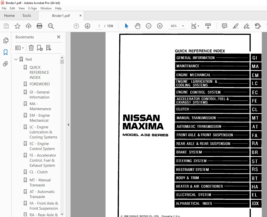
1997 NISSAN MAXIMA A32 Series Service Manual PDF DOWNLOAD
FILE DETAILS:
1997 NISSAN MAXIMA A32 Series Service Manual PDF DOWNLOAD
Language : English
Pages : 1536
Downloadable :Yes
File Type : PDF
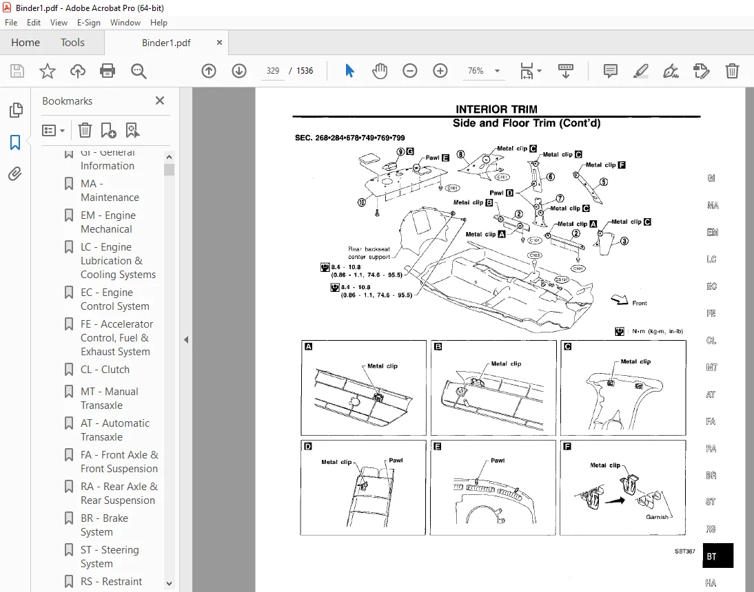
IMAGES PREVIEW OF THE MANUAL:
TABLE OF CONTENTS:
1997 NISSAN MAXIMA A32 Series Service Manual PDF DOWNLOAD
fwd.................................................................................................   1
	QUICK REFERENCE INDEX...........................................................................   1
	FOREWORD........................................................................................   2
	GI - General Information........................................................................   0
	MA - Maintenance ...............................................................................   0
	EM - Engine Mechanical..........................................................................   0
	LC - Engine Lubrication & Cooling Systems.......................................................   0
	EC - Engine Control System......................................................................   0
	FE - Accelerator Control, Fuel & Exhaust System.................................................   0
	CL - Clutch.....................................................................................   0
	MT - Manual Transaxle...........................................................................   0
	AT - Automatic Transaxle........................................................................   0
	FA - Front Axle & Front Suspension..............................................................   0
	RA - Rear Axle & Rear Suspension................................................................   0
	BR - Brake System...............................................................................   0
	ST - Steering System............................................................................   0
	RS - Restraint System...........................................................................   0
	BT - Body & Trim................................................................................   0
	HA - Heater & Air Conditioner...................................................................   0
	EL - Electrical System..........................................................................   0
	IDX - Alphabetical Index........................................................................   1
	Foldout.........................................................................................   0
	Comment Sheet...................................................................................   3
	Quick Reference Chart...........................................................................   4
	GST Mode 6 - Test Value & Test Limit Chart......................................................   5
AT..................................................................................................   6
	QUICK REFERENCE INDEX...........................................................................   0
	TABLE OF CONTENTS...............................................................................   6
	PREPARATION AND PRECAUTIONS.....................................................................   8
		Special Service Tools.......................................................................   8
		Commercial Service Tools....................................................................  11
		Supplemental Restraint System (SRS) "AIR BAG"...............................................  12
		Precautions for On Board Diagnostic ()BD) System of A/T and Engine..........................  12
		Precautions.................................................................................  13
		Service Notice or Precautions...............................................................  14
	OVERALL SYSTEM..................................................................................  15
		A/T Electrical Parts Location...............................................................  15
		Circuit Diagram for Quick Pinpoint Check....................................................  16
		Wiring Diagram - AT -.......................................................................  17
		Cross-sectional View........................................................................  24
		Hydraulic Control Circuit...................................................................  25
		Shift Mechanism.............................................................................  26
		Control System..............................................................................  28
	ON BOARD DIAGNOSTIC SYSTEM DESCRIPTION..........................................................  30
		Introduction................................................................................  30
		One or Two Trip Detection Logic.............................................................  30
		Diagnostic Trouble Code (DTC)...............................................................  30
		Self-diagnosis..............................................................................  32
		Diagnosis by CONSULT........................................................................  37
	TROUBLE DIAGNOSIS - Introduction................................................................  40
		Introduction................................................................................  40
		Diagnostic Worksheet........................................................................  41
		Work Flow...................................................................................  44
	TROUBLE DIAGNOSIS - Basic Inspection............................................................  45
		A/T Fluid Check.............................................................................  45
		Road Test...................................................................................  45
		Shift Schedule..............................................................................  55
	TROUBLE DIAGNOSIS - General Description.........................................................  56
		Diagnostic Trouble Code (DTC) Chart.........................................................  56
		Symptom Chart...............................................................................  58
		A/T Control Unit Terminals and Reference Value..............................................  61
	DTC P0705, Inhibitor, Overdrive Control and Throttle Position Switches..........................  63
	DTC P0710, A/T Fluid Temperature Sensor Circuit and A/T Control Unit Power Source...............  69
	DTC P0720, Vehicle Speed Sensor-A/T (Revolution sensor).........................................  72
	DTC P0725, Engine Speed Signal..................................................................  74
	DTC P0731, Improper Shifting to 1st Gear Position...............................................  76
	DTC P0732, Improper Shifting to 2nd Gear Position...............................................  79
	DTC P0733, Improper Shifting to 3rd Gear Position...............................................  82
	DTC P0734, Improper Shifting to 4th Gear Position...............................................  85
	DTC P0740, Torque Converter Clutch Solenoid Valve...............................................  90
	DTC P0744, Improper Lock-up Operation...........................................................  93
	DTC P0745, Line Pressure Solenoid Valve.........................................................  98
	DTC P0750, Shift Solenoid Valve A............................................................... 101
	DTC P0755, Shift Solenoid Valve B............................................................... 104
	DTC P1705, Throttle Position Sensor............................................................. 107
	DTC P1760, Overrun Clutch Solenoid Valve........................................................ 109
	TROUBLE DIAGNOSIS FOR VHCL SPEED SEN-MTR........................................................ 112
		Vehicle Speed Sensor-MTR.................................................................... 112
	DIAGNOSTIC PROCEDURES FOR SYMPTOMS.............................................................. 114
		1. O/D OFF Indicator Lamp Does Not Come On.................................................. 114
		2. Engine Cannot Be Started In "P" and "N" Position......................................... 115
		3. In "P" Position, Vehicle Moves Forward or Backward When Pushed........................... 115
		4. In "N" Position, Vehicle Moves........................................................... 116
		5. Large Shock. "N" - "R" Position.......................................................... 117
		6. Vehicle Does Not Creep Backward In "R" Position.......................................... 118
		7. Vehicle Does Not Creep Forward in "D", "2" Or "1" Position............................... 119
		8. Vehicle Cannot Be Started From D1........................................................ 120
		9. A/T Does Not Shift: D1 - D2 Or Does Not Kickdown: D4 - D2................................ 121
		10. A/T Does Not Shift: D2 - D3............................................................. 122
		11. A/T Does Not Shift: D3 - D4............................................................. 123
		12. A/T Does Not Perform Lock-up............................................................ 124
		13. A/T Does Not Hold Lock-up Condition..................................................... 125
		14. Lock-up Is Not Released................................................................. 125
		15. Engine Speed Does Not Return To Idle (Light Braking D4 - D3)............................ 126
		16. Vehicle Does Not Start From D1.......................................................... 127
		17. A/T Does Not Shift: D4 - D3, When Overdrive Control Switch "ON" - "OFF"................. 127
		18. A/T Does Not Shift: D3 - 2-2, When Selector Lever "D" - "2" Position.................... 128
		19. A/T Does Not Shift: 2-2 - 1-1, When Selector Lever "2" - "1" Position................... 128
		20. Vehicle Does Not Decelerate By Engine Brake............................................. 129
	TROUBLE DIAGNOSES............................................................................... 130
		Final Check................................................................................. 130
	TROUBLE DIAGNOSES - A/T Shift Lock System....................................................... 135
		A/T Shift Lock System....................................................................... 135
		Wiring Diagram - SHIFT -.................................................................... 136
		Diagnostic Procedure........................................................................ 137
		Key Interlock Cable......................................................................... 139
		Component Check............................................................................. 140
	ON-VEHICLE SERVICE.............................................................................. 142
		Control Valve Assembly and Accumulator...................................................... 142
		Revolution Sensor Replacement............................................................... 143
		Inhibitor Switch Adjustment................................................................. 143
		Control Cable Adjustment.................................................................... 144
		Differential Side Oil Seal Replacement...................................................... 144
	REMOVAL AND INSTALLATION........................................................................ 145
		Removal..................................................................................... 145
		Installation................................................................................ 145
	MAJOR OVERHAUL.................................................................................. 147
		Oil Channel................................................................................. 150
		Locations of Adjusting Shims, Needle Bearings, Thrust Washers and Snap Rings................ 151
	DISASSEMBLY..................................................................................... 152
	REPAIR FOR COMPONENT PARTS...................................................................... 166
		Manual Shaft................................................................................ 166
		Oil Pump.................................................................................... 168
		Control Valve Assembly...................................................................... 172
		Control Valve Upper Body.................................................................... 180
		Control Valve Lower Body.................................................................... 184
		Reverse Clutch.............................................................................. 186
		High Clutch................................................................................. 189
		Forward Clutch and Overrun Clutch........................................................... 193
		Low & Reverse Brake......................................................................... 199
		Rear Internal Gear, Forward Clutch Hub and Overrun Clutch Hub............................... 201
		Output Shaft, Idler Gear, Reduction Pinion Gear and Bearing Retainer........................ 205
		Bank Servo Piston Assembly.................................................................. 210
		Final Drive - RE4F04A....................................................................... 215
		Final Drive - RE4F04V....................................................................... 219
	ASSEMBLY........................................................................................ 224
		Assembly 1.................................................................................. 224
		Adjustment 1................................................................................ 224
		Assembly 2.................................................................................. 229
		Adjustment 2................................................................................ 233
		Assembly 3.................................................................................. 235
	SERVICE DATA AND SPECIFICATIONS (SDS)........................................................... 241
		General Specifications...................................................................... 241
		Specifications and Adjustments.............................................................. 241
BR.................................................................................................. 248
	QUICK REFERENCE INDEX...........................................................................   0
	TABLE OF CONTENTS............................................................................... 248
	PRECAUTIONS AND PREPARATION..................................................................... 250
		Supplemental Restraint System (SRS) "AIR BAG"............................................... 250
		Precautions................................................................................. 250
		Commercial Service Tools.................................................................... 250
	BRAKE HYDRAULIC LINE/CONTROL VALVE.............................................................. 251
		Brake Hydraulic Line........................................................................ 251
		Dual Proportioning Valve.................................................................... 252
	CHECK ADJUSTMENT................................................................................ 253
		Checking Brake Fluid Level.................................................................. 253
		Checking Brake Line......................................................................... 253
		Changing Brake Fluid........................................................................ 253
		Bleeding Brake System....................................................................... 253
	BRAKE PEDAL AND BRACKET......................................................................... 254
		Removal and Installation.................................................................... 254
		Inspection.................................................................................. 254
		Adjustment.................................................................................. 254
	MASTER CYLINDER................................................................................. 255
		Removal..................................................................................... 255
		Disassembly................................................................................. 255
		Inspection.................................................................................. 256
		Assembly.................................................................................... 256
		Installation................................................................................ 256
	BRAKE BOOSTER/VACUUM HOSE....................................................................... 257
		Brake Booster............................................................................... 257
		Vacuum Hose................................................................................. 258
	FRONT DISC BRAKE................................................................................ 259
		Pad Replacement............................................................................. 259
		Removal..................................................................................... 260
		Disassembly................................................................................. 260
		Inspection - Caliper........................................................................ 261
		Inspection - Rotor.......................................................................... 261
		Assembly.................................................................................... 262
		Installation................................................................................ 262
	REAR DISC BRAKE................................................................................. 263
		Pad Replacement............................................................................. 263
		Removal..................................................................................... 265
		Disassembly................................................................................. 265
		Inspection - Caliper........................................................................ 266
		Inspection - Rotor.......................................................................... 267
		Assembly.................................................................................... 267
		Installation................................................................................ 268
	PARKING BRAKE CONTROL........................................................................... 269
		Removal and Installation.................................................................... 269
		Inspection.................................................................................. 270
		Adjustment.................................................................................. 270
	ANTI-LOCK BRAKE SYSTEM.......................................................................... 271
		Purpose..................................................................................... 271
		Operation................................................................................... 271
		ABS Hydraulic Circuit....................................................................... 271
		System Components........................................................................... 272
		System Description.......................................................................... 272
		Removal and Installation.................................................................... 274
	TROUBLE DIAGNOSES............................................................................... 276
		How to Perform Trouble Diagnoses for Quick and Accurate Repair.............................. 276
		Preliminary Check........................................................................... 277
		Component Parts and Harness Connector Location.............................................. 278
		Circuit Diagram for Quick Pinpoint Check.................................................... 279
		Wiring Diagram - ABS -...................................................................... 280
		Self-diagnosis.............................................................................. 284
		CONSULT..................................................................................... 287
		CONSULT Inspection Procedure................................................................ 288
		Ground Circuit Check........................................................................ 293
	TROUBLE DIAGNOSES FOR SELF-DIAGNOSTIC ITEMS..................................................... 294
		Diagnostic Procedure 1 (ABS actuator solenoid valve)........................................ 294
		Diagnostic Procedure 2 (Wheel sensor or rotor).............................................. 296
		Diagnostic Procedure 3 (Motor relay or motor)............................................... 298
		Diagnostic Procedure 4 (Solenoid valve relay)............................................... 301
		Diagnostic Procedure 5 (Low voltage)........................................................ 303
		Diagnostic Procedure 6 (Control unit)....................................................... 304
	TROUBLE DIAGNOSES FOR SYMPTOMS.................................................................. 305
		Diagnostic Procedure 7 (Pedal vibration and noise).......................................... 305
		Diagnostic Procedure 8 (Long stopping distance)............................................. 306
		Diagnostic Procedure 9 (Unexpected pedal action)............................................ 306
		Diagnostic Procedure 10 (ABS does not work.)................................................ 307
		Diagnostic Procedure 11 (ABS works frequently.)............................................. 307
		Diagnostic Procedure 12 (Warning lamp does not work before engine starts.).................. 308
		Diagnostic Procedure 13 (Warning lamp stays on continuously.)............................... 309
	SERVICE DATA AND SPECIFICATIONS (SDS)........................................................... 312
		General Specifications...................................................................... 312
		Inspection and Adjustment................................................................... 312
BT.................................................................................................. 313
	QUICK REFERENCE INDEX...........................................................................   0
	TABLE OF CONTENTS............................................................................... 313
	PRECAUTIONS..................................................................................... 314
		Precaution.................................................................................. 314
		Supplemental Restraint System (SRS) "AIR BAG"............................................... 314
	GENERAL SERVICING............................................................................... 315
		Clip and Fastener........................................................................... 315
	BODY END........................................................................................ 318
		Body Front End.............................................................................. 318
		Body Rear End and Opener.................................................................... 321
	DOOR............................................................................................ 323
		Front Door.................................................................................. 323
		Rear Door................................................................................... 324
	INSTRUMENT PANEL................................................................................ 325
	INTERIOR TRIM................................................................................... 328
		Side and Floor Trim......................................................................... 328
		Door Trim................................................................................... 331
		Roof Trim................................................................................... 332
		Trunk Room Trim............................................................................. 333
	EXTERIOR........................................................................................ 334
	SEAT............................................................................................ 339
		Front Seat.................................................................................. 339
		Heated Seat................................................................................. 341
		Rear Seat................................................................................... 342
	SUNROOF......................................................................................... 343
	WINDSHIELD AND WINDOWS.......................................................................... 347
		Windshield and Rear Window.................................................................. 347
	MIRROR.......................................................................................... 348
		Door Mirror................................................................................. 348
	BODY ALIGNMENT.................................................................................. 349
		Engine Compartment.......................................................................... 349
		Underbody................................................................................... 351
CL.................................................................................................. 353
	QUICK REFERENCE INDEX...........................................................................   0
	TABLE OF CONTENTS............................................................................... 353
	PRECAUTIONS AND PREPARATION..................................................................... 354
		Precautions................................................................................. 354
		Special Service Tools....................................................................... 354
	CLUTCH SYSTEM - Hydraulic Type.................................................................. 355
	INSPECTION AND ADJUSTMENT....................................................................... 356
		Adjusting Clutch Pedal...................................................................... 356
		Bleeding Procedure.......................................................................... 357
	HYDRAULIC CLUTCH CONTROL........................................................................ 358
		Clutch Master Cylinder...................................................................... 358
		Operating Cylinder.......................................................................... 359
	CLUTCH RELEASE MECHANISM........................................................................ 360
	CLUTCH DISC AND CLUTCH COVER.................................................................... 361
		Clutch Disc................................................................................. 361
		Clutch Cover and Flywheel................................................................... 362
	SERVICE DATA AND SPECIFICATIONS (SDS)........................................................... 363
		General Specifications...................................................................... 363
		Inspection and Adjustment................................................................... 363
EC.................................................................................................. 364
	QUICK REFERENCE INDEX...........................................................................   0
	TABLE OF CONTENTS............................................................................... 364
	DIAGNOSTIC TROUBLE CODE INDEX................................................................... 367
		Alphabetical & P No. Index for DTC.......................................................... 367
	PRECAUTIONS AND PREPARATION..................................................................... 369
		Special Service Tool........................................................................ 369
		Commercial Service Tool..................................................................... 369
		Supplemental  Restraint System (SRS) "AIR BAG" ............................................. 370
		Precautions for On Board Diagnostic (OBD) System of Engine and A/T.......................... 370
		Engine Fuel & Emission Control System....................................................... 370
		Precautions................................................................................. 372
	ENGINE AND EMISSION CONTROL OVERALL SYSTEM...................................................... 374
		Circuit Diagram............................................................................. 374
		System Diagram.............................................................................. 375
		ECCS Component Parts Location............................................................... 376
		Vacuum Hose Drawing......................................................................... 379
		System Chart................................................................................ 380
	ENGINE AND EMISSION BASIC CONTROL SYSTEM DECRIPTION............................................. 381
		Multiport Fuel Injection (MFI) System....................................................... 381
		Electronic Ignition (EI) System............................................................. 383
		Air Conditioning Cut Control................................................................ 384
		Fuel Cut Control (at no load & high engine speed)........................................... 385
	EVAPORATE EMISSION SYSTEM....................................................................... 386
		Description................................................................................. 386
		Inspection.................................................................................. 386
		Evaporate Emission Line Drawing............................................................. 388
	POSITIVE CRANKCASE VENTILATION.................................................................. 390
		Description................................................................................. 390
		Inspection.................................................................................. 390
	BASIC SERVICE PROCEDURE......................................................................... 391
		Fuel Pressure Release....................................................................... 391
		Fuel Pressure Check......................................................................... 391
		Injector Removal and Installation........................................................... 391
		Fast Idle Cam (FIC) Inspection and Adjustment............................................... 393
		Direct Ignition System - How to Check Idle Speed and Ignition Timing........................ 394
		Idle Speed/Ignition Timing/Idle Mixture Ratio Adjustment.................................... 396
	ON BOARD DIAGNOSTIC SYSTEM DESCRIPTION.......................................................... 403
		Introduction................................................................................ 403
		Two Trip Detection Logic.................................................................... 403
		Emission-related Diagnostic Information..................................................... 404
		Malfunction Indicatior Lamp (MIL)........................................................... 415
		OBD System Operation Chart.................................................................. 419
		CONSULT..................................................................................... 424
		Generic Scan Tool (GST)..................................................................... 437
	TROUBLE DIAGNOSIS - General Description......................................................... 439
		Introduction................................................................................ 439
		Diagnostic Worksheet........................................................................ 439
		Work Flow................................................................................... 441
		Description for Work Flow................................................................... 442
		Basic Inspection............................................................................ 443
		Diagnostic Trouble Code (DTC) Inspection Priority Chart..................................... 446
		Fail-Safe Chart............................................................................. 447
		Symptom Matrix chart........................................................................ 448
		CONSULT Reference Value in Data Monitor Mode................................................ 451
		Major Sensor Reference Graph in Data Monitor Mode........................................... 454
		ECM Terminals and Reference Value........................................................... 456
	TROUBLE DIAGNOSIS FOR POWER SUPPLY.............................................................. 464
		Main Power Supply and Ground Circuit........................................................ 464
	DTC P0100, Mass Air Flow Sensor (MAFS).......................................................... 469
	DTC P0105, Absolute Pressure Sensor............................................................. 475
	DTC P0110, Intake Air  Temperature Sensor....................................................... 482
	DTC P0115, Engine Coolant Temperature Sensor (ECTS)............................................. 488
	DTC P0120, Throttle Position Sensor............................................................. 493
	DTC P0125, Engine Coolant Temperature Sensor (ECTS)............................................. 499
	DTC P0130, P0150, Closed Loop Control........................................................... 504
	DTC P0130, Front Heated Oxygen Sensor (Front H02S) ) Right bank)................................ 506
	DTC P0135, Front Heated Oxygen Sensor Heater (Right bank)....................................... 511
	DTC P0136, Rear Heated Oxygen Sensor (Rear H02S) ............................................... 515
	DTC P0141, Rear Heated Oxygen Sensor Heater..................................................... 519
	DTC P0150, Front Heated Oxygen Sensor (Front H02S) (Left bank).................................. 524
	DTC P0155, Front Heated Oxygen Sensor Heater (Left bank)........................................ 530
	DTC P0171, Fuel Injection System Function (Right bank) (Lean side).............................. 534
	DTC P0172, Fuel Injection System Function (Right bank) (Rich side).............................. 539
	DTC P0174, Fuel Injection System Function (Left bank) (Lean side)............................... 544
	DTC P0175, Fuel Injection System Function (Left bank) (Rich side)............................... 549
	DTC P0180, Tank Fuel Temperature Sensor......................................................... 554
	DTC P0306 - P0300, No. 6 - 1 Cylinder Misfire, Multiple Cylinder Misfire........................ 557
	DTC P0325, Knock Sensor (KS).................................................................... 561
	DTC P0335, Crankshaft Position Sensor (CKPS) (POS).............................................. 564
	DTC P0340, Camshaft Position Sensor (CMPS) (PHASE).............................................. 570
	DTC P0400, EGR Function......................................................................... 575
	DTC P0402, EGRC-BPT Valve Function.............................................................. 585
	DTC P0420, Three Way Catalyst Function.......................................................... 587
	DTC P0440, Evaporate Emission (EVAP) Control System (Small Leak)................................ 590
	DTC P0443, Evporate Emission (EVAP) Canister Purge Control Valve/Solenoid Valve................. 598
	DTC P0446, Evaporate Emission (EVAP) Canister Vent Control Valve................................ 606
	DTC P0450, Evaporate Emission (EVAP) Control System Pressure Sensor............................. 611
	DTC P0500, Vehicle Speed Sensor (VSS)........................................................... 616
	DTC P0505. Idle Air Control Valve (IACV) - Auxillary Air Control (AAC) Valve.................... 620
	DTC P0510, Closed Throttle Position Switch...................................................... 626
	DTC P0600, A/T Control.......................................................................... 630
	DTC P0605, Engine Control Module (ECM)-ECCS Control Module...................................... 634
	DTC P0705, Park/Neautral Position Switch........................................................ 637
	DTC P1105. Manifold Absolute Pressure (MAP)/Barometric Pressure (BARO) Switch Solenoid Valve.... 642
	DTC P1220, Fuel Pump Control Module (FPCM)...................................................... 648
	DTC P1320, Iginition Signal..................................................................... 655
	DTC P1335, Crankshaft Position Sensor (CKPS) (REF).............................................. 663
	DTC P1336, Crankshaft Position Sensor (CKPS) (POS) (COG)........................................ 668
	DTC P1400, EGRC-Solenoid Valve.................................................................. 674
	DTC P1401, EGR Temperature Sensor............................................................... 679
	DTC P1441, Vacuum Cut Valve Bypass Valve........................................................ 683
	DTC P1445, Evaporate Emission (EVAP) Canister Purge Volume Control Valve........................ 688
	DTC P1447, Evaporate Emission (EVAP) Control System Purge Flow Monitoring....................... 695
	DTC P1605, A/T Diagnosis Communication Line..................................................... 702
	DTC P1900, Overheat............................................................................. 705
	TROUBLE DIAGNOSIS FOR NON-DETACHABLE ITEMS...................................................... 718
		Injector.................................................................................... 718
		Start Signal................................................................................ 723
		Fuel Pump Control........................................................................... 725
		Front Engine Mounting Control............................................................... 730
		Power Steering Oil Pressure Switch.......................................................... 733
		IACV-FICD Solenoid Valve.................................................................... 738
		Electrical Load Signal...................................................................... 741
		MIL & Data Link Connectors.................................................................. 744
	SERVICE DATA AND SPECIFICATIONS (SDS)........................................................... 745
		General Specifications...................................................................... 745
		Inspection and Adjustment................................................................... 745
EL.................................................................................................. 747
	QUICK REFERENCE INDEX...........................................................................   0
	TABLE OF CONTENTS............................................................................... 747
	PRECAUTIONS..................................................................................... 750
		Supplemental Restraint System (SRS) "AIR BAG"............................................... 750
	HARNESS CONNECTOR............................................................................... 751
		Description................................................................................. 751
	STANDARDIZED RELAY.............................................................................. 752
		Description................................................................................. 752
	POWER SUPPLY ROUTING............................................................................ 754
		Schematic................................................................................... 754
		Wiring Diagram - POWER -.................................................................... 755
		Fuse........................................................................................ 767
		Fusible Link................................................................................ 767
		Circuit Breaker Inspection.................................................................. 767
	GROUND DISTRIBUTION............................................................................. 768
	BATTERY......................................................................................... 772
		How to Handle Battery....................................................................... 772
		Service Data and Specifications (SDS)....................................................... 775
	STARTING SYSTEM................................................................................. 776
		System Description.......................................................................... 776
		Wiring Diagram - START -.................................................................... 778
		Construction................................................................................ 782
		Removal and Installation.................................................................... 782
		Pinion/Clutch Check......................................................................... 783
		Service Data and Specifications (SDS)....................................................... 783
	CHARGING SYSTEM................................................................................. 784
		System Description.......................................................................... 784
		Wiring Diagram - CHARGE -................................................................... 785
		Trouble Diagnoses........................................................................... 786
		Construction................................................................................ 787
		Removal and Installation.................................................................... 787
		Service Data and Specifications (SDS)....................................................... 788
	COMBINATION SWITCH.............................................................................. 789
		Combination Switch/Check.................................................................... 789
		Replacement................................................................................. 790
		Steering Switch/Check....................................................................... 791
	HEADLAMP........................................................................................ 792
		System Description (For USA)................................................................ 792
		Wiring Diagram - H/LAMP -................................................................... 793
		Trouble Diagnoses (For USA)................................................................. 794
		System Description (For Canada)............................................................. 795
		Operation (For Canada)...................................................................... 796
		Schematic................................................................................... 796
		Wiring Diagram (For Canada) - DTRL -........................................................ 797
		Trouble Diagnoses (For Canada).............................................................. 800
		Bulb Replacement............................................................................ 802
		Bulb Specifications......................................................................... 802
		Aiming Adjustment........................................................................... 802
	EXTERIOR LAMP................................................................................... 804
		Parking, License and Tail Lamps/Wiring Diagram - TAIL/L -................................... 804
		Stop Lamp/Wiring Diagram - STOP/L -......................................................... 806
		Back-up Lamp/Wiring Diagram - BACK/L -...................................................... 808
		Front Fog Lamp/System Description........................................................... 809
		Front Fog Lamp/Wiring Diagram - F/FOG -..................................................... 810
		Front Fog Lamp Aiming Adjustment............................................................ 811
		Bulb Specifications......................................................................... 811
		Turn Signal and Hazard Warning Lamps/System Description..................................... 812
		Turn Signal and Hazard Warning Lamps/Schematic.............................................. 813
		Turn Signal and Hazard Warning Lamps/Wiring Diagram - TURN -................................ 814
		Turn Signal and Hazard Warning Lamps/Trouble Diagnoses...................................... 817
		Combination Flasher Unit Check.............................................................. 817
		Bulb Specifications......................................................................... 818
	INTERIOR LAMP................................................................................... 819
		Illumination/System Description............................................................. 819
		Illumination/Schematic...................................................................... 820
		Illumination/Wiring Diagram - ILL -......................................................... 821
		Spot and Trunk Room Lamp/Wiring Diagram - INT/L -........................................... 825
		Bulb Specifications......................................................................... 826
	METERS AND GAUGES............................................................................... 827
		System Description.......................................................................... 827
		Combination Meter........................................................................... 828
		Speedometer, Tachometer, Temp. and Fuel Gauges/Wiring Diagram - METER -..................... 829
		Trouble Diagnoses........................................................................... 831
		Fuel Tank Gauge Unit Check.................................................................. 834
		Thermal Transmitter Check................................................................... 834
		Vehicle Speed Sensor Signal Check........................................................... 834
	WARNING LAMPS................................................................................... 835
		Schematic................................................................................... 835
		Wiring Diagram - WARN -..................................................................... 836
		Fuel Warning Lamp Sensor Check.............................................................. 840
		Oil Pressure Switch Check................................................................... 840
		Diode Check................................................................................. 840
	WARNING BUZZER.................................................................................. 841
		System Description.......................................................................... 841
		Wiring Diagram - BUZZER -................................................................... 842
		Trouble Diagnoses........................................................................... 844
	WIPER AND WASHER................................................................................ 850
		System Description.......................................................................... 850
		Front Wiper and Washer/Wiring diagram - WIPER -............................................. 852
		Trouble Diagnoses........................................................................... 854
		Installation................................................................................ 860
		Wiper Leakage............................................................................... 861
		Washer Nozzle Adjustment.................................................................... 861
		Check Valve (Built in washer nozzles)....................................................... 861
	HORN, CIGARETTE LIGHTER, CLOCK.................................................................. 862
		Wiring Diagram - HORN -..................................................................... 862
	REAR WINDOW DEFOGGER............................................................................ 864
		System Description.......................................................................... 864
		Wiring diagram - DEF -...................................................................... 865
		Trouble Diagnoses........................................................................... 867
		Filament Check.............................................................................. 871
		Filament Repair............................................................................. 872
	AUDIO AND POWER ANTENNA......................................................................... 873
		Audio/System Description.................................................................... 873
		Audio/Schematic............................................................................. 874
		Audio/Wiring Diagram - AUDIO -.............................................................. 875
		Power Antenna/System Description............................................................ 880
		Power Antenna/Wiring Diagram - P/ANT -...................................................... 881
		Trouble Diagnoses........................................................................... 882
		Location of Antenna......................................................................... 884
		Antenna Rod Replacement..................................................................... 884
		Window Antenna Repair....................................................................... 885
	TELEPHONE....................................................................................... 887
		Telephone Pre Wire/Wiring Diagram - PHONE -................................................. 887
	ELECTRIC SUNROOF................................................................................ 888
		Sunroof/Wiring Diagram - SROOF -............................................................ 888
	POWER SEAT...................................................................................... 889
		Power Seat/Wiring Diagram - SEAT -.......................................................... 889
	HEATED SEAT..................................................................................... 891
		Heated Seat/Wiring Diagram - HSEAT -........................................................ 891
	POWER DOOR MIRROR............................................................................... 892
		Wiring Diagram - MIRROR -................................................................... 892
	TRUNK LID AND FUEL FILLER LID OPENER............................................................ 893
		Wiring Diagram - TLID -..................................................................... 893
	AUTOMATIC SPEED CONTROL DEVICE (ASCD)........................................................... 894
		Component Parts and Harness Connector Location.............................................. 894
		System Description.......................................................................... 895
		Schematic................................................................................... 897
		Wiring Diagram - ASCD -..................................................................... 899
		Trouble Diagnoses........................................................................... 904
	IVMS (LAN) - SYSTEM DESCRIPTION................................................................. 918
		Overall Description......................................................................... 918
		Component Parts Location.................................................................... 920
		System Diagram.............................................................................. 921
		Sleep/Wake-up Control....................................................................... 922
		Fail-safe System............................................................................ 922
		Body Control Module (BCM)................................................................... 923
		Local Conrol Units (LCUs)................................................................... 926
	IVMS (LAN) - TROUBLE DIAGNOSES SYSTEM........................................................... 933
		CONSULT..................................................................................... 933
		IVMS Communication Diagnoses Results List................................................... 937
		On-board Diagnosis.......................................................................... 940
		On-board Diagnosis - Mode I (IVMS communication diagnosis).................................. 941
		On-board Diagnosis - Mode II (Switch monitor)............................................... 943
	IVMS - (LAN) - TROUBLE DIAGNOSES................................................................ 945
		Main Power Supply, Ground and Communication Circuits/Wiring Diagram - COMM -................ 945
		Work Flow................................................................................... 948
		Power Supply and Ground Circuit Check....................................................... 949
		Data Lines Circuit Check.................................................................... 951
		Replacing the BCM (Body Control Module) for Models with Auto A/C............................ 952
	POWER WINDOW - IVMS............................................................................. 954
		System Description.......................................................................... 954
		Schematic................................................................................... 955
		Wiring Diagram - WINDOW -................................................................... 956
		Trouble Diagnoses........................................................................... 960
	POWER DOOR LOCK - IVMS.......................................................................... 969
		System Description.......................................................................... 969
		Schematic................................................................................... 970
		Wiring Diagram - D/LOCK -................................................................... 971
		Trouble Diagnoses........................................................................... 975
	MULTI-REMOTE CONTROL SYSTEM - IVMS.............................................................. 988
		System Description.......................................................................... 988
		Schematic................................................................................... 990
		Wiring Diagram - MULTI -.................................................................... 991
		Trouble Diagnoses........................................................................... 998
		Replacing Remote Controller or Control Unit.................................................1007
	THEFT WARNING SYSTEM - IVMS.....................................................................1008
		Component Parts and Harness Connector Location..............................................1008
		System Description..........................................................................1009
		Schematic...................................................................................1012
		Wiring Diagram - THEFT -....................................................................1014
		Trouble Diagnoses...........................................................................1021
	ILLUMINATION - IVMS.............................................................................1035
		System Description..........................................................................1035
		Wiring Diagram - SW/ILL -...................................................................1036
		Trouble Diagnoses...........................................................................1037
	INTERIOR LAMP CONTROL - IVMS....................................................................1039
		System Description..........................................................................1039
		Wiring Diagram - ROOM/L.....................................................................1040
		Trouble Diagnoses...........................................................................1042
	STEP LAMP - IVMS................................................................................1047
		System Description..........................................................................1047
		Wiring Diagram - STEP/L -...................................................................1048
		Trouble Diagnoses...........................................................................1050
	INTEGRATED HOMELINK TRANSMITTER.................................................................1053
		Wiring Diagram - TRNSMT -...................................................................1053
		Trouble Diagnoses...........................................................................1054
	LOCATION OF ELECTRICAL UNITS....................................................................1055
		Engine Compartment..........................................................................1055
		Passenger Compartment.......................................................................1056
		Luggage Compartment.........................................................................1057
	HARNESS LAYOUT..................................................................................1059
		Outline.....................................................................................1059
		How to Read Harness Layout..................................................................1060
		Engine Room Harness.........................................................................1061
		Main Harness................................................................................1064
		Engine Control Harness......................................................................1066
		Body Harness................................................................................1068
		Body No. 2 Harness and Tail Harness.........................................................1070
		Room Lamp Harness...........................................................................1071
		Air Bag Harness.............................................................................1071
		Door Harness (LH side)......................................................................1072
		Door Harness (RH side)......................................................................1073
	SUPER MULTIPLE JUNCTION (SMJ)...................................................................   0
		Terminal Arrangement........................................................................   1
	FUSE BLOCK - Junction Box (J/B).................................................................   2
		Terminal Arrangement........................................................................   3
	ELECTRICAL UNITS................................................................................   4
		Terminal Arrangement........................................................................   4
	JOINT CONNECTOR (J/C)...........................................................................   5
		Terminal Arrangement........................................................................   5
EM..................................................................................................1074
	QUICK REFERENCE INDEX...........................................................................   0
	TABLE OF CONTENTS...............................................................................1074
	PRECAUTIONS.....................................................................................1075
		Parts Reuiring Angular Tightening...........................................................1075
		Liquid Gasket Application Procedure.........................................................1075
	PREPARATION.....................................................................................1076
		Special Service Tools.......................................................................1076
		Commercial Service Tools....................................................................1078
	OUTER COMPONENT PARTS...........................................................................1079
	COMPRESSION PRESSURE............................................................................1083
		Measurement of Compression Pressure.........................................................1083
	OIL PAN.........................................................................................1084
		Removal.....................................................................................1084
		Installation................................................................................1087
	TIMING CHAIN....................................................................................1090
		Removal.....................................................................................1092
		Inspection..................................................................................1099
		Installation................................................................................1099
	OIL SEAL REPLACEMENT............................................................................1104
	CYLINDER HEAD...................................................................................1107
		Removal.....................................................................................1108
		Diassembly..................................................................................1108
		Inspection..................................................................................1110
		Assembly....................................................................................1114
		Installation................................................................................1115
	VALVE CLEARANCE.................................................................................1120
		Checking....................................................................................1120
		Adjusting...................................................................................1120
	ENGINE REMOVAL..................................................................................1124
		Removal.....................................................................................1125
		Installation................................................................................1126
	CYLINDER BLOCK..................................................................................1127
		Disassembly.................................................................................1128
		Inspeciton..................................................................................1128
		Assembly....................................................................................1128
	SERVICE DATA AND SPECIFICATIONS (SDS)...........................................................1138
		General Specifications......................................................................1138
		Inspection adn Adjustiment..................................................................1138
FA..................................................................................................1146
	QUICK REFERENCE INDEX...........................................................................   0
	TABLE OF CONTENTS...............................................................................1146
	PRECAUTIONS AND PREPARATION.....................................................................1147
		Precautions.................................................................................1147
		Special Service Tools.......................................................................1147
		Commercial Service Tools....................................................................1148
	FRONT SUSPENSION SYSTEM.........................................................................1149
	ON-VEHICLE SERVICE..............................................................................1150
		Front Axle and Front Suspension Parts.......................................................1150
		Front Wheel Bearing.........................................................................1151
		Front Wheel Alignment.......................................................................1151
		Drive Shaft.................................................................................1152
	FRONT AXLE......................................................................................1153
		Wheel Hub and Knuckle.......................................................................1153
		Drive Shaft.................................................................................1157
	FRONT SUSPENSION................................................................................1165
		Coil Spring and Strut Assembly..............................................................1166
		Stabilizer Bar..............................................................................1167
		Transverse Link and Lower Ball Joint........................................................1168
	SERVICE DATA AND SPECIFICATIONS (SDS)...........................................................1170
		General Specifications......................................................................1170
		Inspection and Adjustment...................................................................1171
FE..................................................................................................1172
	QUICK REFERENCE INDEX...........................................................................   0
	TABLE OF CONTENTS...............................................................................1172
	PREPARATION/ACCELERATOR CONTROL SYSTEM..........................................................1173
		Special Service Tool........................................................................1173
		Adjusting Accelerator Wire..................................................................1173
	FUEL SYSTEM.....................................................................................1174
	EXHAUST SYSTEM..................................................................................1175
Foldout.............................................................................................1176
	QUICK REFERENCE INDEX...........................................................................   0
	ELECTRICAL SYSTEM...............................................................................   2
	SUPER MULTIPLE JUNCTION (SMJ)...................................................................1176
		Terminal Arrangement........................................................................1177
	FUSE BLOCK - Junction Box ( J/B)................................................................1178
	FUSE AND FUSIBLE LINK BOX.......................................................................1179
		Terminal Arrangement........................................................................1179
	ELECTRICAL UNITS................................................................................1180
		Terminal Arrangement........................................................................1180
	JOINT CONNECTOR (J/C)...........................................................................1181
		Terminal Arrangement........................................................................1181
GI..................................................................................................1182
	QUICK REFERENCE INDEX...........................................................................   0
	TABLE OF CONTENTS...............................................................................1182
	PRECAUTIONS.....................................................................................1183
		Precautions for Supplemental Restraint System "AIR BAG".....................................1183
		General Precautions.........................................................................1183
		Precautions for Multiport Fuel Injection System or ECCS Engine..............................1183
		Precauitions for Three Way Catalyst.........................................................1185
		Precautions for Engine Oils ................................................................1186
		Precautions for Fuel........................................................................1187
		Precautions for Air Conditioning............................................................1187
	HOW TO USE THIS MANUAL..........................................................................1188
	HOW TO READ WIRING DIAGRAMS.....................................................................1190
		Sample/Wiring Diagram - EXAMPL -............................................................1190
		Description.................................................................................1192
		Wiring Diagram Codes (Cell Codes)...........................................................1199
	HOW TO PERFORM EFFICIENT DIAGNOSIS FOR AN ELECTRICAL INCIDENT...................................1201
		Work Flow...................................................................................1201
		Incident Simulation Tests...................................................................1202
		Circuit Inspection..........................................................................1206
	HOW TO FOLLOW FLOW CHART IN TROUBLE DIAGNOSES...................................................1206
	CONSULT CHECKING SYSTEM.........................................................................1215
		Function and System Application.............................................................1215
		Lithium Battery Replacement.................................................................1215
		Checking Equipment..........................................................................1215
	IDENTIFICATION INFORMATION......................................................................1216
		Model Variation.............................................................................1216
		Identification Number.......................................................................1217
		Dimensions..................................................................................1219
		Wheels and Tires............................................................................1219
	LIFTING POINTS AND TOW TRUCK TOWING.............................................................1220
		Preparation.................................................................................1220
		Board-on Lift...............................................................................1220
		Garage Jack and Safety Stand................................................................1221
		2-pole Lift.................................................................................1222
		Tow Truck Towing............................................................................1223
	TIGHTENING TORQUE OF STANDARD BOLTS.............................................................1224
	SAE J1930 TERMINOLOGY LIST......................................................................1225
		SAE J1930 Terminology List..................................................................1225
HA..................................................................................................1229
	QUICK REFERENCE INDEX...........................................................................   0
	TABLE OF CONTENTS...............................................................................1229
	MANUAL AND AUTO.................................................................................1231
		PRECAUTIONS AND PREPARATION.................................................................1231
			Supplemental Restraint System (SRS) "AIR BAG"...........................................1231
			Precautions for Working with HFC-134a (R-134a)..........................................1231
			General Refrigerant Precautions.........................................................1231
			Precautions for Refrigerant Connection..................................................1232
			Precautions for Servicing Compressor....................................................1235
			Special Service Tools...................................................................1235
			HFC-134a (r-134a) Service Tools and Equipment...........................................1236
			Precautions for Service Equipment.......................................................1238
		DESCRIPTION.................................................................................1240
			Refrigeration Cycle.....................................................................1240
			V-6 Variable Displacement Compressor....................................................1241
			Component Layout........................................................................1245
			Discharge Air Flow......................................................................1246
	MANUAL..........................................................................................1247
		DESCRIPTION.................................................................................1247
			Control Operation.......................................................................1247
		TROUBLE DIAGNOSES...........................................................................1249
			Contents................................................................................1249
	MANUAL AND AUTO.................................................................................1260
		TROUBLE DIAGNOSES...........................................................................1260
			Performace Test Diagnoses...............................................................1260
			Performance Chart.......................................................................1262
			Trouble Diagnoses for Abnormal Pressure.................................................1263
	MANUAL..........................................................................................1266
		TROUBLE DIAGNOSES...........................................................................1266
			Wiring Diagram - A/C,M -................................................................1269
	AUTO............................................................................................1288
		DESCRIPTION.................................................................................1288
			Introduction............................................................................1288
			Features................................................................................1288
			Conrol Operation........................................................................1289
		TROUBLE DIAGNOSES...........................................................................1291
			Contents................................................................................1291
			Wiring Diagram - A/C,A -................................................................1320
		SYSTEM DESCRIPTION..........................................................................1343
			Overview of Control System..............................................................1343
			Control System Input Components.........................................................1344
			Control System Automatic Amplifier (Auto amp.)..........................................1346
			Control system Output Components........................................................1346
	MANUAL AND AUTO.................................................................................1354
		SERVICE PROCEDURES..........................................................................1354
			HFC-134a (R-134a) Service Procedure.....................................................1354
			Maintenance of Lubricant Quantity in Compressor.........................................1356
			Refrigerant Lines.......................................................................1358
			Checking Refrigerant Leaks..............................................................1359
			Compressor Mounting.....................................................................1361
			Belt Tension............................................................................1361
			Fast Idle Control Device................................................................1361
			Compressor..............................................................................1362
			Compressor Clutch.......................................................................1362
	AUTO............................................................................................1366
		SERVICE PROCEDURES..........................................................................1366
			Replacing a/C Autp Amp..................................................................1366
	MANUAL AND AUTO.................................................................................1368
		SERVICE DATA AND SPECIFICATIONS (SDS).......................................................1368
			General Specifications..................................................................1368
			Inspection and Adjustment...............................................................1368
IDX.................................................................................................1369
	QUICK REFERENCE INDEX...........................................................................   0
LC..................................................................................................1376
	QUICK REFERENCE INDEX...........................................................................   0
	TABLE OF CONTENTS...............................................................................1376
	PRECAUTIONS AND PREPARATION.....................................................................1377
		Liquid Gasket Application Procedure.........................................................1377
		Special Service Tools.......................................................................1378
	ENGINE LUBRICATION SYSTEM.......................................................................1379
		Lubrication Circuit.........................................................................1379
		Oil Pressure Check..........................................................................1380
		Oil Pump....................................................................................1380
	ENGINE COOLING SYSTEM...........................................................................1383
		Cooling Circuit.............................................................................1383
		System Check................................................................................1384
		Water Pump..................................................................................1384
		Thermostat..................................................................................1389
		Radiator....................................................................................1389
		Cooling Fan Control System..................................................................1390
		Radiator (Aluminum type)....................................................................1391
		Overheating Cause Analysis..................................................................1394
	SERVICE DATA AND SPECIFICATIONS.................................................................1395
		Engine Lubrication..........................................................................1395
		Engine Cooling System.......................................................................1395
MA..................................................................................................1396
	QUICK REFERENCE INDEX...........................................................................   0
	TABLE OF CONTENTS...............................................................................1396
	PRECAUTIONS AND PREPARATION.....................................................................1397
		Supplemental Restraint System (SRS) "AIR BAG"...............................................1397
		Special Service Tool........................................................................1397
	GENERAL MAINTENANCE.............................................................................1398
	PERIODIC MAINTENANCE............................................................................1400
		Schedule 1..................................................................................1401
		Schedule 2..................................................................................1402
	RECOMMENDED FLUIDS AND LUBRICANTS...............................................................1403
		Fluids and Lubricants.......................................................................1403
		SAE Viscosity Number........................................................................1403
		Anti-freeze Coolant Mixture Ratio...........................................................1404
	ENGINE MAINTENANCE..............................................................................1405
		Checking Drive Belts........................................................................1405
		Changing Engine Coolant.....................................................................1406
		Checking Fuel Lines.........................................................................1407
		Changing Fuel Filter........................................................................1407
		Changing Air Cleaner Filter.................................................................1408
		Changing Engine Oil.........................................................................1409
		Changing Oil  Filter........................................................................1409
		Changing Spark Plugs........................................................................1410
		Checking EVAP Vapor Purge Lines.............................................................1411
	CHASSIS AND BODY MAINTENANCE....................................................................1412
		Checking Exhaust System.....................................................................1412
		Checking Clutch Fluid Level and Leaks.......................................................1412
		Checking M/T Oil............................................................................1412
		Changing M/T Oil............................................................................1412
		Checking A/T Fluid..........................................................................1413
		Changing A/T Fluid..........................................................................1413
		Balancing Wheels............................................................................1414
		Tire Rotation...............................................................................1414
		Checking Brake Fluid Level and Leaks........................................................1414
		Checking Brake Lines and Cables.............................................................1414
		Checking Disc Brake.........................................................................1414
		Checking Steering Gear and Linkage..........................................................1415
		Checking Power Steering Fluid and Lines.....................................................1415
		Lubricating Locks, Hinges and Hood Latches..................................................1416
		Checking Seat Belts, Buckles, Retractors, Anchors and Adjusters.............................1416
	SERVICE DATA AND SPECIFICATIONS (SDS)...........................................................1417
		Engine Maintenance..........................................................................1417
		Chassis and Body Maintenance................................................................1417
MT..................................................................................................1418
	QUICK REFERENCE INDEX...........................................................................   0
	TABLE OF CONTENTS...............................................................................1418
	PREPARATION.....................................................................................1419
		Special Service Tools.......................................................................1419
		Commercial Service Tools....................................................................1421
	DESCRIPTION.....................................................................................1422
		Cross - Sectional View......................................................................1422
	ON-VEHICLE SERVICE/REMOVAL AND INSTALLATION.....................................................1423
		Replacing Oil Seal..........................................................................1423
		Position Switch Check.......................................................................1424
		Viscous Coupling Check......................................................................1424
		Removal.....................................................................................1424
		Installation................................................................................1425
	TRANSAXLE GEAR CONTROL..........................................................................1426
	MAJOR OVERHAUL..................................................................................1427
		Case Components.............................................................................1427
		Gear Components.............................................................................1428
		Shift Control Components....................................................................1429
	DISASSEMBLY.....................................................................................1430
	REPAIR FOR COMPONENT PARTS......................................................................1433
		Input Shaft Gears...........................................................................1433
		Mainshaft and Gears.........................................................................1438
		Final Drive.................................................................................1442
		Shift Control Components....................................................................1448
		Case Components.............................................................................1448
	ADJUSTMENT......................................................................................1449
		Input Shaft End Play and Differential Side Bearing Preload..................................1449
		Mainshaft Bearing Preload...................................................................1450
	ASSEMBLY........................................................................................1453
	SERVICE DATA AND SPECIFICATIONS (SDS)...........................................................1457
		General Specifications......................................................................1457
		Inspection and Adjustment...................................................................1457
RA..................................................................................................1462
	QUICK REFERENCE INDEX...........................................................................   0
	TABLE OF CONTENTS...............................................................................1462
	PRECAUTIONS AND PREPARATION.....................................................................1463
		Precautions.................................................................................1463
		Preparation.................................................................................1463
	REAR SUSPENSION.................................................................................1464
	ON-VEHICLE SERVICE..............................................................................1465
		Rear Axle and Rear Suspension Parts.........................................................1465
		Rear Wheel Bearing..........................................................................1465
		Rear Wheel Alignment........................................................................1466
	REAR AXLE.......................................................................................1467
		Wheel Hub...................................................................................1467
	REAR SUSPENSION.................................................................................1470
		Removal and Installation....................................................................1471
		Coil Spring and Shock Absorber..............................................................1471
		Torsion Beam, Lateral Link and control Rod..................................................1473
	SERVICE DATA AND SPECIFICATIONS (SDS)...........................................................1474
		General Specifications......................................................................1474
		Inspection and Adjustment...................................................................1474
RS..................................................................................................1475
	QUICK REFERENCE INDEX...........................................................................   0
	TABLE OF CONTENTS...............................................................................1475
	PRECAUTION......................................................................................1476
		Supplemental Restraint System (SRS) "AIR BAG"...............................................1476
	SEAT BELTS......................................................................................1477
		Front Seat Belt.............................................................................1477
		Rear Seat Belt..............................................................................1478
	SUPPLEMENTAL RESTRAINT SYSTEM (SRS).............................................................1479
		Precautions for SRS "Air Bag" Service.......................................................1479
		Special Service Tools.......................................................................1479
		Description.................................................................................1480
		SRS Component Parts Location................................................................1480
		Maintenance Items...........................................................................1481
		Removal and Installation - Diagnosis Sensor Unit............................................1482
		Removal and Installation - Air Bag Module and Spiral Cable..................................1482
		Removal - Air Bag Module and Spiral Cable...................................................1483
		Removal - Front Passenger Air Bag Module....................................................1484
		Installation - Air Bag Module and Spiral Cable..............................................1485
		Installation - Front Passenger Air Bag Module...............................................1486
		Disposal of Air Bag Module..................................................................1487
	TROUBLE DIAGNOSES - Supplemental Restraint Sytem (SRS)..........................................1491
		How to Perform Trouble Diagnoses for Quick and Accurate Repair..............................1491
		Schematic...................................................................................1493
		Wiring Diagram - SRS -......................................................................1494
		Self-diagnosis..............................................................................1496
		Trouble Diagnoses for Air Bag Warning Lamp..................................................1508
	COLLISION DIAGNOSIS.............................................................................1510
ST..................................................................................................1511
	QUICK REFERENCE INDEX...........................................................................   0
	TABLE OF CONTENTS...............................................................................1511
	PRECAUTIONS AND PREPARATION.....................................................................1512
		Precautions.................................................................................1512
		Special Service Tools.......................................................................1512
		Commercial Service Tools....................................................................1513
	ON-VEHICLE SERVICE..............................................................................1514
		Checking Steering Wheel Play................................................................1514
		Checking Neutral Position on Steering Wheel.................................................1514
		Front Wheel Turning Angle...................................................................1514
		Checking Gear Housing Movement..............................................................1514
		Checking and Adjusting Drive Belts (For power steering).....................................1515
		Checking Fluid Level........................................................................1515
		Checking Fluid Leakage......................................................................1515
		Bleeding Hydraulic system...................................................................1515
		Checking Steering Wheel Turning Force (For power steering)..................................1516
		Checking Hydraulic System...................................................................1517
	STEERING WHEEL AND STEERING COLUMN..............................................................1518
		Removal and Installation....................................................................1518
		Disassembly and Assembly....................................................................1520
		Inspection..................................................................................1521
	POWER STEERING GEAR AND LINKAGE.................................................................1522
		Removal and Installation....................................................................1522
		Disassembly.................................................................................1525
		Inspection..................................................................................1526
		Assembly....................................................................................1526
		Adjustment..................................................................................1531
	POWER STEERING OIL PUMP.........................................................................1532
		Pre-disassembly Inspection..................................................................1532
		Disassembly.................................................................................1533
		Inspection..................................................................................1533
		Assembly....................................................................................1534
	SERVICE DATA AND SPECIFICATIONS (SDS)...........................................................1535
		General Specificaitons......................................................................1535
		Inspection and Adjustment...................................................................1535
Contact us: [email protected]
https://vimeo.com/852067688?share=copy
DESCRIPTION:
1997 NISSAN MAXIMA A32 Series Service Manual PDF DOWNLOAD
FOREWORD
- This manual contains maintenance and repair procedures for the 1997 Nissan MAXIMA.
- In order to assure your safety and the efficient functioning of the vehicle, this manual should be read thoroughly.
- It is especially important that the PRECAUTIONS in the GI section be completely understood before starting any repair task.
- All information in this manual is based on the latest product information at the time of publication. The right is reserved to make changes in specifications and methods at any time without notice.
IMPORTANT SAFETY NOTICE
- The proper performance of service is essential for both the safety of the technician and the efficient functioning of the vehicle.
- The service methods in this Service Manual are described in such a manner that the service may be performed safely and accurately.
- Service varies with the procedures used, the skills of the technician and the tools and parts available.
- Accordingly, anyone using service procedures, tools or parts which are not specifically recommended by NISSAN must first be completely satisfied that neither personal safety nor the vehicle’s safety will be jeopardized by the service method selected.
PLEASE NOTE:
- This is the same manual used by the dealers to diagnose and troubleshoot your vehicle
- You will be directed to the download page as soon as the purchase is completed. The whole payment and downloading process will take anywhere between 2-5 minutes
- Need any other service / repair / parts manual, please feel free to contact [email protected] . We still have 50,000 manuals unlisted
G.P