Trusted Business
Verified & Licensed
Virus Free Files
100% Safe Downloads
Secure Payment
SSL Protected
Instant Delivery
Available Immediately
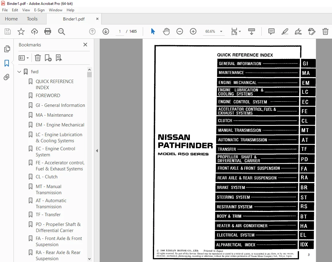
1997 NISSAN PATHFINDER R50 Series Service Manual PDF DOWNLOAD
$24.95
1997 NISSAN PATHFINDER R50 Series Service Manual PDF DOWNLOAD
Instant PDF Download
Available immediately
Save to Your Device
Download & keep forever
Antivirus Scanned
100% virus-free
Trusted Worldwide
175,000+ customers
Description
1997 NISSAN PATHFINDER R50 Series Service Manual PDF DOWNLOAD
FILE DETAILS:
1997 NISSAN PATHFINDER R50 Series Service Manual PDF DOWNLOAD
Language : English
Pages : 1485
Downloadable : Yes
File Type : PDF
IMAGES PREVIEW OF THE MANUAL:
TABLE OF CONTENTS:
1997 NISSAN PATHFINDER R50 Series Service Manual PDF DOWNLOAD
fwd...................................................................................................   1
	QUICK REFERENCE INDEX.............................................................................   1
	FOREWORD..........................................................................................   2
	GI - General Information..........................................................................   0
	MA - Maintenance..................................................................................   0
	EM - Engine Mechanical............................................................................   0
	LC - Engine Lubrication & Cooling Systems.........................................................   0
	EC - Engine Control System........................................................................   0
	FE - Accelerator control, Fuel & Exhaust Systems..................................................   0
	CL - Clutch.......................................................................................   0
	MT - Manual Transmission..........................................................................   0
	AT - Automatic Transmission.......................................................................   0
	TF - Transfer.....................................................................................   0
	PD - Propeller Shaft & Differential Carrier.......................................................   0
	FA - Front Axle & Front Suspension................................................................   0
	RA - Rear Axle & Rear Suspension..................................................................   0
	BR - Brake System.................................................................................   0
	ST - Steering System..............................................................................   0
	RS - Restraint System.............................................................................   0
	BT - Body & Trim..................................................................................   0
	HA - Heater & Air Conditioner.....................................................................   0
	EL - Electrical System............................................................................   0
	IDX - Alphabetical Index..........................................................................   1
	Foldout...........................................................................................   0
	Comment Sheet.....................................................................................   3
	Quick Reference Chart.............................................................................   4
	GST Mode 6 - Test Value & Test Limit Chart........................................................   5
at....................................................................................................   6
	QUICK REFERENCE INDEX.............................................................................   0
	TABLE OF CONTENTS.................................................................................   6
	PREPARATION AND PRECAUTIONS.......................................................................   8
		Special Service Tools.........................................................................   8
		Supplemental Restraint System (SRS) "AIR BAG".................................................   9
		Precautions for On Board Diagnostic (OBD) System of A/T and Entine............................   9
		Precautions...................................................................................  10
		Service Notice or Precautions.................................................................  11
	OVERALL SYSTEM....................................................................................  12
		A/T Electrical Parts Location.................................................................  12
		Circuit Diagram...............................................................................  13
		Wiring Diagram - AT -.........................................................................  14
		Cross-sectional View..........................................................................  20
		Hydraulic Control Circuit.....................................................................  21
		Shift Mechanism...............................................................................  22
		Control System................................................................................  24
	ON BOARD DIAGNOSTIC SYSTEM DESCRIPTION............................................................  26
		Introduction..................................................................................  26
		One or Two Trip Detection Logic...............................................................  26
		Diagnostic Trouble Code (DTC).................................................................  26
		Self-diagnosis................................................................................  28
		Diagnosis by CONSULT..........................................................................  33
	TROUBLE DIAGNOSIS - Introduction..................................................................  36
		Introduction..................................................................................  36
		Diagnostic Worksheet..........................................................................  37
		Work Flow.....................................................................................  40
	TROUBLE DIAGNOSIS - Basic Inspection..............................................................  41
		A/T Fluid Check...............................................................................  41
		Road Test.....................................................................................  41
		Shift Schedule................................................................................  51
	TROUBLE DIAGNOSIS - General Description...........................................................  52
		Diagnostic Trouble Code (DTC) Chart...........................................................  52
		Symptom Chart.................................................................................  54
		A/T Control Unit Terminals and Reference Value................................................  57
	DTC P0705, Inhibitor, Overdrive Control and Throttle Position Switches............................  61
	DTC P0710, A/T Fluid Temperature Sensor Circuit and A/T Control Unit Power Source.................  67
	DTC P0720, Vehicle Speed - Sensor - A/T (Revolution sensor).......................................  70
	DTC P0725, Engine Speed Signal....................................................................  72
	DTC P0731, Improper Shifting to 1st Gear Position.................................................  74
	DTC P0732, Improper Shifting to 2nd Gear Position.................................................  77
	DTC P0733, Improper Shifting to 3rd Gear Position.................................................  79
	DTC P0734, Improper Shifting to 4th Gear Position.................................................  81
	DTC P0740, Torque Converter Clutch Solenoid Valve.................................................  86
	DTC P0744, Improper Lock-up Operation.............................................................  89
	DTC P0745, Line Pressure Solenoid Valve...........................................................  94
	DTC P0750, Shift Solenoid Valve A.................................................................  97
	DTC P0755, Shift Solenoid Valve B................................................................. 100
	DTC P1705, Throttle Position Sensor............................................................... 103
	DTC P1760, Overrun Clutch Solenoid Valve.......................................................... 105
	TROUBLE DIAGNOSIS FOR VHCL SPEED SEN-MTR.......................................................... 108
		Vehicle Speed Sensor - MTR.................................................................... 108
	DIAGNOSTIC PROCEDURES FOR SYMPTOMS................................................................ 110
		1. O/D OFF Indicator Lamp Does Not Come On.................................................... 110
		2. Engine Cannot Be Started in "P" and "N" Position........................................... 111
		3. In "P" Position, Vehicle Moves Forward Or Backward When Pushed............................. 111
		4. In "N" Position, Vehicle Moves............................................................. 112
		5. Large Shock. "N" - "R" Position............................................................ 113
		6. Vehicle Does Not Creep Backward In "R" Position............................................ 114
		7. Vehicle Does Not Creep Forward In "D", "2" Or "1" Position................................. 115
		8. Vehicle Cannot Be Started From D1.......................................................... 116
		9. A/T Does Not Shift: D1 - D2 Or Does Not Kickdown: D4 - D2.................................. 117
		10. A/T Does Not Shift: D2 - D3............................................................... 118
		11. A/T Does Not Shift: D3 - D4............................................................... 119
		12. A/T Does Not Perform Lock-up.............................................................. 120
		13. A/T Does Not Hold Lock-up Condition....................................................... 121
		14. Lock-up Is Not Released................................................................... 121
		15. Engine Speed Does Not Return To Idle (Light Braking D4 - D3).............................. 122
		16. Vehicle Does Not Start From D1............................................................ 123
		17. A/T Does Not Shift: D4 - D3, When Overdrive Control Switch "ON" - "OFF"................... 123
		18. A/T Does Not Shift: D3 - 22, When Selector Lever "D" - "2" Position....................... 125
		19. A/T Does Not Shift: 22 - 11, When Selector Lever "2" - "1" Position....................... 124
		20. Vehicle Does Not Decelerate By Engine Brake............................................... 126
	TROUBLE DIAGNOSES................................................................................. 126
		Final Check................................................................................... 126
	TROUBLE DIAGNOSES - A/T Shift Lock System......................................................... 131
		Description................................................................................... 131
		Wiring Diagram - SHIFT - ..................................................................... 132
		Diagnostic Procedure.......................................................................... 133
		Key Interlock Cable........................................................................... 135
		Component Check............................................................................... 137
	ON-VEHICLE SERVICE................................................................................ 138
		Control Valve Assembly and Accumulators Inspection............................................ 138
		Revolution Sensor Replacement................................................................. 139
		Rear Oil Seal Replacement..................................................................... 139
		Parking Components Inspection................................................................. 139
		Inhibitor Switch Adjustment................................................................... 140
		Manual Control Linkage Adjustment............................................................. 140
	REMOVAL AND INSTALLATION.......................................................................... 141
		Removal....................................................................................... 141
		Installation.................................................................................. 142
	MAJOR OVERHAUL.................................................................................... 144
		Oil Channel................................................................................... 146
		Locations of Needle Bearings, Thrust Washers and Snap Rings................................... 147
	DISASSEMBLY....................................................................................... 148
		Disassembly................................................................................... 148
	REPAIR FOR COMPONENT PARTS........................................................................ 159
		Oil Pump...................................................................................... 159
		Control Valve Assembly........................................................................ 163
		Control Valve Upper Body...................................................................... 169
		Control Valve Lower Body...................................................................... 174
		Reverse Clutch................................................................................ 176
		High Clutch................................................................................... 180
		Forward and Overrun Clutches.................................................................. 182
		Low & Reverse Brake........................................................................... 186
		Forward Clutch Drum Assembly.................................................................. 190
		Rear Internal Gear and Forward Clutch Hub..................................................... 192
		Band Servo Piston Assembly.................................................................... 195
		Parking Pawl Components....................................................................... 199
	ASSEMBLY.......................................................................................... 201
		Assembly (1).................................................................................. 201
		Adjustment.................................................................................... 205
		Assembly (2).................................................................................. 209
	A/T FLUID COOLER SYSTEM........................................................................... 219
		A/T Fluid Cooler.............................................................................. 219
	SERVICE DATA AND SPECIFICATIONS (SDS)............................................................. 220
		General Specifications........................................................................ 220
		Specifications and Adjustment................................................................. 220
br.................................................................................................... 224
	QUICK REFERENCE INDEX.............................................................................   0
	TABLE OF CONTENTS................................................................................. 224
	PRECAUTIONS AND PREPARATION....................................................................... 226
		Precautions................................................................................... 226
		Special Service Tool.......................................................................... 226
		Commercial Service Tools...................................................................... 227
	CHECK AND ADJUSTMENT.............................................................................. 228
		Checking Brake Fluid Level.................................................................... 228
		Checking Brake Line........................................................................... 228
		Changing Brake Fluid.......................................................................... 228
		Bleeding Brake System......................................................................... 229
	BRAKE HYDRAULIC LINE/CONTROL VALVE................................................................ 230
		Brake Hydraulic Line.......................................................................... 230
		Proportioning Valve (2WD)..................................................................... 232
		Load Sensing Valve (4WD)...................................................................... 233
	BRAKE PEDAL AND BRAKET............................................................................ 236
		Removal and Installation...................................................................... 236
		Inspection.................................................................................... 236
		Adjustment.................................................................................... 236
	MASTER CYLINDER................................................................................... 238
		Removal....................................................................................... 238
		Disassembly................................................................................... 239
		Inspection.................................................................................... 239
		Assembly...................................................................................... 239
		Installation.................................................................................. 240
	BRAKE BOOSTER..................................................................................... 241
		Brake Booster................................................................................. 241
	VACUUM PIPING..................................................................................... 243
		Vacuum Hose................................................................................... 243
	FRONT DISC BRAKE.................................................................................. 244
		Pad Replacement............................................................................... 244
		Removal....................................................................................... 246
		Disassembly................................................................................... 246
		Inspection - Caliper.......................................................................... 246
		Inspection - Rotor............................................................................ 247
		Assembly...................................................................................... 247
		Installation.................................................................................. 247
	REAR DRUM BRAKE (LT30C)........................................................................... 248
		Removal....................................................................................... 248
		Inspection - Wheel Cylinder................................................................... 249
		Wheel Cylinder Overhaul....................................................................... 250
		Inspection - Drum............................................................................. 250
		Inspection - Lining........................................................................... 250
		Installation.................................................................................. 250
	PARKING BRAKE CONTROL............................................................................. 252
		Removal and Installation...................................................................... 252
		Inspection.................................................................................... 252
		Adjustment.................................................................................... 253
	ANTI-LOCK BRAKE SYSTEM............................................................................ 254
		Purpose....................................................................................... 254
		Operation..................................................................................... 254
		ABS Hydraulic Circuit......................................................................... 254
		System Components............................................................................. 255
		System Description............................................................................ 255
		Removal and Installation...................................................................... 258
	TROUBLE DIAGNOSES................................................................................. 262
		How to Perform Trouble Diagnoses for Quick and Accurate Repair................................ 262
		Preliminary Check............................................................................. 263
		Component Parts and Harness Connector Location................................................ 264
		Circuit Diagram for Quick Pinpoint check...................................................... 265
		Wiring Diagram - ABS -........................................................................ 266
		Self-diagnosis................................................................................ 270
		CONSULT....................................................................................... 273
		CONSULT Inspection Procedure.................................................................. 274
		Ground Circuit Check.......................................................................... 279
	TROUBLE DIAGNOSES FOR SELF-DIAGNOSTIC ITEMS....................................................... 280
		Diagnostic Procedure 1 (Wheel sensor or rotor)................................................ 280
		Diagnostic Procedure 2 (ABS actuator solenoid valve).......................................... 282
		Diagnostic Procedure 3 (Solenoid valve relay)................................................. 284
		Diagnostic Procedure 4 (Motor relay or motor)................................................. 287
		Diagnostic Procedure 5 (Low voltage).......................................................... 290
		Diagnostic Procedure 6 (G sensor)............................................................. 291
		Diagnostic Procedure 7 (Control unit)......................................................... 292
	TROUBLE DIAGNOSES FOR SYMPTOMS.................................................................... 293
		Diagnostic Procedure 8 (ABS works frequently.)................................................ 293
		Diagnostic Procedure 9 (Unexpected pedal action............................................... 294
		Diagnostic Procedure 10 (Long stopping distance).............................................. 294
		Diagnostic Procedure 11 (ABS does not work.).................................................. 295
		Diagnostic Procedure 12 (Pedal vibration and noise)........................................... 295
		Diagnostic Procedure 13 (Warning lamp does not come on when ignition switch is turned on.).... 296
		Diagnostic Procedure 14 (Warning lamp stays on when ignition switch is turned on..)........... 298
	SERVICE DATA AND SPECIFICATIONS (SDS)............................................................. 301
		General Specifications........................................................................ 301
		Inspection and Adjustment..................................................................... 302
bt.................................................................................................... 303
	QUICK REFERENCE INDEX.............................................................................   0
	TABLE OF CONTENTS................................................................................. 303
	PRECAUTIONS....................................................................................... 304
		Service Notice................................................................................ 304
		Supplemental Restraint System (SRS) "AIR BAG"................................................. 304
	GENERAL SERVICING................................................................................. 305
		Clip and Fastener............................................................................. 305
	BODY END.......................................................................................... 307
		Body Front End................................................................................ 307
		Body Rear End and Opener...................................................................... 309
	DOOR.............................................................................................. 311
		Front Door.................................................................................... 311
		Rear Door..................................................................................... 312
	INSTRUMENT PANEL.................................................................................. 313
		Side and Floor Trim........................................................................... 317
		Door Trim..................................................................................... 319
		Roof Trim..................................................................................... 320
		Back Door Trim................................................................................ 321
	EXTERIOR.......................................................................................... 322
	SEAT.............................................................................................. 328
		Front Seat.................................................................................... 328
		Heated Seat................................................................................... 330
		Rear Seat..................................................................................... 331
	SUNROOF........................................................................................... 332
	WINDSHIELD AND WINDOWS............................................................................ 336
		Windshield.................................................................................... 336
		Rear Side Window.............................................................................. 337
	MIRROR............................................................................................ 338
		Door Mirror................................................................................... 338
	BODY ALIGNMENT.................................................................................... 339
		Engine Compartment............................................................................ 339
		Underbody..................................................................................... 341
cl.................................................................................................... 343
	QUICK REFERENCE INDEX.............................................................................   0
	TABLE OF CONTENTS................................................................................. 343
	PRECAUTIONS AND PREPARATION....................................................................... 344
		Precautions................................................................................... 344
		Special Service Tools......................................................................... 344
		Commercial Service Tools...................................................................... 344
	CLUTCH SYSTEM - Hydraulic Type.................................................................... 345
	INSPECTION AND ADJUSTMENT......................................................................... 346
		Adjusting Clutch Pedal........................................................................ 346
		Bleeding Procedure............................................................................ 347
	HYDRAULIC CLUTCH CONTROL.......................................................................... 348
		Clutch Master Cylinder........................................................................ 348
		Operating Cylinder............................................................................ 349
		Clutch Damper................................................................................. 350
	CLUTCH RELEASE MECHANISM.......................................................................... 351
	CLUTCH DISC AND CLUTCH COVER...................................................................... 353
		Clutch Disc................................................................................... 353
		Clutch Cover and Flywheel..................................................................... 354
	SERVICE DATA AND SPECIFICATIONS (SDS)............................................................. 355
		General Specifications........................................................................ 355
		Inspection and Adjustment..................................................................... 355
ec.................................................................................................... 356
	QUICK REFERENCE INDEX.............................................................................   0
	TABLE OF CONTENTS................................................................................. 356
	DIAGNOSTIC TROUBLE CODE INDEX..................................................................... 359
		Alphabetical & P No. Index for DTC............................................................ 359
	PRECAUTIONS AND PREPARATION....................................................................... 361
		Special Service Tools......................................................................... 361
		Commercial Service Tool....................................................................... 361
		Supplemental Restraint System (SRS) "AIR BAG"................................................. 361
		Precautions for On Board Diagnostic (OBD) System of Engine and A/T............................ 362
		Engine Fuel & Emission Control System......................................................... 363
		Precautions................................................................................... 364
	ENGINE AND EMISSION CONTROL OVERALL SYSTEM........................................................ 366
		ECCS Component Parts Location................................................................. 366
		Circuit Diagram............................................................................... 368
		System Diagram................................................................................ 369
		Vacuum Hose Drawing........................................................................... 370
		System Chart.................................................................................. 371
	ENGINE AND EMISSION BASIC CONTROL SYSTEM DESCRIPTION.............................................. 372
		Multiport Fuel Injection (MFI) system......................................................... 372
		Distributor Ignition (DI) System.............................................................. 374
		Air Conditioning Cut Control.................................................................. 375
		Fuel Cut Control (at no load & high engine speed)............................................. 376
	EVAPORATIVE EMISSION SYSTEM....................................................................... 377
		Description................................................................................... 377
		Inspection.................................................................................... 377
		Evaporative Emission Line Drawing............................................................. 379
	POSITIVE CRANKCASE VENTILATION.................................................................... 381
		Description................................................................................... 381
		Inspection.................................................................................... 381
	BASIC SERVICE PROCEDURE........................................................................... 381
		Fuel Pressure Release......................................................................... 381
		Fuel Pressure Check........................................................................... 381
		Injector Removal and Installation............................................................. 383
		Fast Idle Cam (FIC) Inspection and Adjustment................................................. 384
		Idle Speed/Ignition Timing/Idle Mixture Ratio Adjustment...................................... 386
	ON BOARD DIAGNOSTIC SYSTEM DESCRIPTION............................................................ 393
		Introduction.................................................................................. 393
		Two Trip Detection Logic...................................................................... 393
		Emission-related Diagnostic Information....................................................... 394
		Malfunction Indicator Lamp (MIL).............................................................. 405
		OBD System Operation Chart.................................................................... 408
		CONSULT....................................................................................... 413
		Generic Scan Tool (GST)....................................................................... 425
	TROUBLE DIAGNOSIS - Introduction.................................................................. 427
		Introduction.................................................................................. 427
		Diagnostic Worksheet.......................................................................... 427
	TROUBLE DIAGNOSIS - Work Flow..................................................................... 429
		Work Flow..................................................................................... 429
		Description for Work Flow..................................................................... 430
	TROUBLE DIAGNOSIS - Basic Inspection.............................................................. 431
		Basic Inspection.............................................................................. 431
	TROUBLE DIAGNOSIS - General Description........................................................... 433
		Diagnostic Trouble Code (DTC) Inspection Priority Chart....................................... 433
		Fail-Safe Chart............................................................................... 434
		Symptom Matrix Chart.......................................................................... 435
		CONSULT Reference Value in Data Monitor Mode.................................................. 438
		Major Sensor Reference Graph in Data Monitor Mode............................................. 440
		ECM Terminals and Reference Value............................................................. 440
	TROUBLE DIAGNOSIS FOR POWER SUPPLY................................................................ 451
		Main Power Supply and Ground Circuit.......................................................... 451
	DTC P0100, Mass Air Flow Sensor (MAFS)............................................................ 456
	DTC P0105, Absolute Pressure Sensor............................................................... 462
	DTC P0110, Intake Air Temperature Sensor.......................................................... 468
	DTC P0115, Engine Coolant Temperature Sensor (ECTS)............................................... 473
	DTC P0120, Throttle Position Sensor............................................................... 478
	DTC P0125, Engine Coolant Temperature (ECT) Sensor................................................ 484
	DTC P0130, P0150, Closed Loop Control............................................................. 489
	DTC P0130, Front Heated Oxygen Sensor (Front HO2S) (Right bank)................................... 490
	DTC P0135, Front Heated Oxygen Sensor Heater (Right bank)......................................... 495
	DTC P0136, Rear Heated Oxygen Sensor (Rear HO2S) (Right bank)..................................... 499
	DTC P0141, Rear Heated oxygen Sensor Heater (Right bank).......................................... 503
	DTC P0150, Front Heated Oxygen Sensor (Front HO2S) (Left bank).................................... 508
	DTC P0155, Front Heated Oxygen Sensor Heater (Left bank).......................................... 513
	DTC P0156, Rear Heated Oxygen Sensor (Rear HO2S) (Left bank)...................................... 517
	DTC P0161, Rear Heated Oxygen Sensor Heater (Left bank)........................................... 521
	DTC P0171, Fuel Injection System Function (Right bank) (Lean side)................................ 525
	DTC P0172, Fuel Injection System Function (Right bank) (Rich side)................................ 530
	DTC P0174, Fuel Injection System Function (Left bank) (Lean side)................................. 535
	DTC P0175, Fuel Injection System Function (Left bank) (Righ side)................................. 540
	DTC P0180, Tank Fuel Temperature Sensor........................................................... 545
	DTC P0300 - P0306, No. 6 - 1 Cylinder Misfire, Multiple Cylinder Misfire.......................... 548
	DTC P0325, Knock Sensor (KS)...................................................................... 552
	DTC P0335, Crankshaft Position Sensor (CKPS) (OBD)................................................ 555
	DTC P0340, Camshaft Position Sensor (CMPS)........................................................ 560
	DTC P0400, EGR Function........................................................................... 566
	DTC P0402, EGRC-BPT Valve Function................................................................ 574
	DTC P0420, P0430, Three Way Catalyst Function..................................................... 576
	DTC P0440, Evaporative Emission (EVAP) Control System (Small Leak)................................ 579
	DTC P0443, Evaporative Emission (EVAP) Canister Purge Control Valve/Solenoid Valve................ 587
	DTC P0446, Evaporative Emission (EVAP) Canister Vent Control Valve................................ 595
	DTC P0450, Evaporative Emission (EVAP) Control System Pressure Sensor............................. 600
	DTC P0500, Vehicle Speed Sensor (VSS)............................................................. 605
	DTC P0505, Idle Air Control Valve (IACV) - Auxiliary Air Control (AAC) Valve...................... 609
	DTC P0510, Closed Throttle Position Switch........................................................ 614
	DTC P0600, A/T Control............................................................................ 618
	DTC P0605, Engine Control Module (ECM) - ECCS Control Module...................................... 621
	DTC P0705, Park/Neutral Position Switch........................................................... 623
	DTC P1105, Manifold Absolute Pressure (MAP)/Barometric Pressure (BARO) Switch Solenoid Valve...... 630
	DTC P1320, Ignition Signal........................................................................ 636
	DTC P1336, Crankshaft Position Sensor (CKPS) (OBD) (COG).......................................... 642
	DTC P1400, EGRC - Solenoid Valve.................................................................. 647
	DTC P1401, EGR Temperature Sensor................................................................. 652
	DTC P1441, Vacuum Cut Valve Bypass Valve.......................................................... 656
	DTC P1445, Evaporative Emission (EVAP) Canister Purge Volume Control Valve........................ 661
	DTC P1447, Evaporative Emission (EVAP) Control System Purge Flow Monitoring....................... 668
	DTC P1605, A/T Diagnosis Communication Line....................................................... 675
	TROUBLE DIAGNOSES FOR NON-DETECTABLE ITEMS........................................................ 678
		Injection..................................................................................... 678
		Start Signal.................................................................................. 682
		Fuel Pump..................................................................................... 685
		Power Steering Oil Pressure Switch............................................................ 690
		IACV - FICD Solenoid Valve.................................................................... 694
		MIL & Data Link Connectors.................................................................... 698
	SERVICE DATA AND SPECIFICATIONS (SDS)............................................................. 699
		General Specifications........................................................................ 699
		Inspection and Adjustment..................................................................... 699
el.................................................................................................... 701
	QUICK REFERENCE INDEX.............................................................................   0
	TABLE OF CONTENTS................................................................................. 701
	PRECAUTIONS....................................................................................... 704
	Supplemental Restraint System (SRS) "AIR BAG"..................................................... 704
	HARNESS CONNECTOR................................................................................. 705
		Description................................................................................... 705
	STANDARDIZED RELAY................................................................................ 706
	Description....................................................................................... 706
	POWER SUPPLY ROUTING.............................................................................. 708
		Schematic..................................................................................... 708
		Wiring Diagram _ POWER -...................................................................... 709
		Fuse.......................................................................................... 720
		Fusible Link.................................................................................. 720
		Circuit Breaker Inspection.................................................................... 720
	GROUND DISTRIBUTION............................................................................... 721
	BATTERY........................................................................................... 724
		How to Handle Battery......................................................................... 724
		Service Data and Specifications (SDS)......................................................... 727
	STARTING SYSTEM................................................................................... 728
		System Description............................................................................ 728
		Wiring Diagram - START -...................................................................... 730
		Construction.................................................................................. 733
		Removal and Installation...................................................................... 733
		Pinion/Clutch Check........................................................................... 734
		Service Data and Specifications (SDS)......................................................... 734
	CHARGING SYSTEM................................................................................... 735
		System Description............................................................................ 735
		Wiring Diagram - CHARGE -..................................................................... 736
		Trouble Diagnoses............................................................................. 737
		Construction.................................................................................. 738
		Removal and Installation...................................................................... 738
		Service Data and Specificiations (SDS)........................................................ 739
	COMBINATION SWITCH................................................................................ 740
		Combination Switch/Check...................................................................... 740
		Replacement................................................................................... 741
		Steering Switch/Check......................................................................... 742
	HEADLAMP.......................................................................................... 743
		System Description (For USA).................................................................. 743
		Wiring Diagram (For USA) - H/LAMP -........................................................... 744
		Trouble Diagnoses (For USA)................................................................... 745
		Daytime Light System/System Description (for Canada).......................................... 746
		Operation (Daytime light system for Canada)................................................... 746
		Schematic (For Canada)........................................................................ 748
		Wiring Diagram (for Canada) - DTRL - ......................................................... 749
		Trouble Diagnoses (For Canada)................................................................ 752
		Bulb Replacement.............................................................................. 753
		Bulb specifications........................................................................... 753
		Aiming  Adjustment............................................................................ 753
	EXTERIOR LAMP..................................................................................... 755
		Parking, License and Tail Lamps/Schematic..................................................... 755
		Parking, License and Tail Lamps/Wiring Diagram - TAIL/L -..................................... 756
		Stop Lamp/Wiring Diagram - STOP/L -........................................................... 759
		Back-up Lamp/Wiring Diagram - BACK/L -........................................................ 761
		Front Fog Lamp/System Description............................................................. 763
		Front Fog Lamp/Wiring Diagram - F/FOG -....................................................... 764
		Front Fog Lamp Aiming Adjustment.............................................................. 765
		Bulb Specifications........................................................................... 765
		Turn Signal and Hazard Warning Lamps/System Description....................................... 766
		Turn Signal and Hazard Warning Lamps/Schematic................................................ 768
		Turn Signal and Hazard Warning Lamps/Wiring Diagram - TURN -.................................. 769
		Turn Signal and Hazard Warning Lamps/Trouble Diagnoses........................................ 772
		Combination Flasher Unit Check................................................................ 772
		Bulb Specifications........................................................................... 773
	INTERIOR LAMP..................................................................................... 774
		Illumination/System Description............................................................... 774
		Illumination/Schematic........................................................................ 775
		Illumination/Wiring Diagram - ILL -........................................................... 776
		Interior, Spot and Luggage Room Lamps/System Description...................................... 780
		Bulb Specifications........................................................................... 780
		Interior, Spot and Luggage Room Lamps/Schematic............................................... 781
		Interior, Spot and Luggage Room Lamps/Wiring Diagram - INT/L -................................ 782
		Wiring Diagram - INT/L -...................................................................... 782
	METER AND GAUGES.................................................................................. 785
		System Description............................................................................ 785
		Combination Meter............................................................................. 786
		Combination Meter, Compass and Thermomenter /Schematic........................................ 787
		Thermometer/Wiring Diagram - METER -.......................................................... 788
		Trouble Diagnoses............................................................................. 791
	WARNING LAMPS..................................................................................... 797
		Warning Lamps/Schematic....................................................................... 797
		Warning Lamps/Wiring Diagram - WARN -......................................................... 798
		Electrical Components Inspection.............................................................. 805
	WARNING BUZZER.................................................................................... 806
		Warning Buzzer/System Description............................................................. 806
		Warning Buzzer/Wiring Diagram - BUZZER -...................................................... 807
		Trouble Diagnoses............................................................................. 809
	WIPER AND WASHER.................................................................................. 813
		System Description............................................................................ 813
		Front Wiper and Washer/Wiring Diagram - WIPER -............................................... 815
		Trouble Diagnoses............................................................................. 817
		Wiper Installation and Adjustment............................................................. 819
		Washer Nozzle Adjustment...................................................................... 819
		Washer Tube Layout............................................................................ 820
		Wiper Linkage................................................................................. 820
		Rear Wiper and Washer/System Description...................................................... 821
		Rear Wiper and Washer/Schematic............................................................... 823
		Rear Wiper and Washer/Wiring Diagram - WIP/R -................................................ 824
		Rear Wiper Trouble Diagnoses.................................................................. 827
		Rear Wiper Installation and Adustment......................................................... 827
		Rear Washer Nozzle Adjustment................................................................. 828
		Washer Tube Layout............................................................................ 828
		Check Valve (for rear washer)................................................................. 828
	HORN AND CIGARETTE LIGHTER........................................................................ 829
		Schematic..................................................................................... 829
		Wiring Diagram - HORN -....................................................................... 830
	REAR WINDOW DEFOGGER.............................................................................. 833
		System Description............................................................................ 833
		Wiring Diagram - DEF -........................................................................ 834
		Trouble Diagnoses............................................................................. 836
		Filament Check................................................................................ 837
		Filament Repair............................................................................... 838
	AUDIO AND POWER ANTENNA........................................................................... 840
		Audio/System Description...................................................................... 840
		Audio (With speaker amp.)/Schematic........................................................... 841
		Audio (With speaker amp.)/Wiring Diagram - AUDIO -............................................ 842
		Audio (Without speaker amp.)/Wiring Diagram - AUDIO -......................................... 846
		Audio (BOSE system)/Schematic................................................................. 848
		Audio (BOSE System)/Wiring Diagram - AUDIO -.................................................. 849
		Power Antenna/System Description.............................................................. 853
		Power Antenna/Wiring Diagram - P/ANT -........................................................ 854
		Trouble Diagnoses............................................................................. 855
		Location of Antenna........................................................................... 857
		Antenna Rod Replacmenet....................................................................... 858
	POWER SUNROOF..................................................................................... 859
		Wiring Diagram - SROOF -...................................................................... 859
	DOOR MIRROR....................................................................................... 860
		Wiring Diagram - MIRROR -..................................................................... 860
	POWER SEAT........................................................................................ 861
		Power Seat/Wiring Diagram - SEAT -............................................................ 861
	HEATED SEAT ...................................................................................... 863
		Heated Seat/Wiring Diagram - HSEAT -.......................................................... 863
	AUTOMATIC SPEED CONTROL DEVICE (ASCD)............................................................. 864
		Component Parts and Harness Connector Location................................................ 864
		System Description............................................................................ 865
		Schematic..................................................................................... 867
		Wiring Diagram - ASCD - ...................................................................... 868
		Trouble Diagnoses............................................................................. 873
		ASCD Wire Adjustment.......................................................................... 883
	POWER WINDOW...................................................................................... 884
		System Description............................................................................ 884
		Schematic..................................................................................... 886
		Wiring Diagram - WINDOW -..................................................................... 887
		Trouble Diagnoses............................................................................. 891
	POWER DOOR LOCK................................................................................... 892
		System Description............................................................................ 892
		Schematic..................................................................................... 894
		Wiring Diagram - D/LOCK -..................................................................... 895
		Trouble Diagnoses............................................................................. 898
	MULTI-REMOTE CONTROL SYSTEM....................................................................... 901
		System Description............................................................................ 901
		Schematic..................................................................................... 903
		Wiring Diagram - MULTI -...................................................................... 904
		Trouble Diagnoses............................................................................. 908
		Replacing Remote Controller or Control Unit................................................... 915
	THEFT WARNING SYSTEM.............................................................................. 916
		Component Parts and Harness Connector Location................................................ 916
		System Description............................................................................ 917
		Schematic..................................................................................... 920
		Wiring Diagram - THEFT -...................................................................... 922
		Trouble Diagnoses............................................................................. 928
	SMART ENTRANCE CONTROL UNIT....................................................................... 941
		Description................................................................................... 941
		Schematic..................................................................................... 942
		Input/Output Operation Signal................................................................. 944
	INTEGRATED HOMELINK TRANSMITTER................................................................... 945
		Wiring Diagram - TRNSMT....................................................................... 945
		Trouble Diagnoses............................................................................. 946
	LOCATION OF ELECTRICAL UNITS...................................................................... 947
		Engine Compartment............................................................................ 947
		Passenger Compartment......................................................................... 948
	HARNESS LAYOUT.................................................................................... 950
		Outline....................................................................................... 950
		How to Read Harness Layout.................................................................... 951
		Main Harness.................................................................................. 952
		Engine Room Harness........................................................................... 954
		Engine Control Harness........................................................................ 956
		Body Harness LH............................................................................... 958
		Body Harness RH............................................................................... 959
		Back Door Harness............................................................................. 960
		Engine and Transmission Harness............................................................... 961
		Room Lamp..................................................................................... 962
		Air Bag Harness............................................................................... 963
		Door Harness (LH side)........................................................................ 964
		Door Harness (RH side)........................................................................ 965
	SUPER MULTIPLE JUNCTION (SMJ)..................................................................... 965
		Terminal Arrangement.......................................................................... 965
	FUSE BLOCK - Junction Box (J/B)................................................................... 965
		Terminal Arrangement.......................................................................... 965
	FUSE AND FUSIBLE LINK BOX......................................................................... 965
		Terminal Arrangement.......................................................................... 965
	ELECTRICAL UNITS.................................................................................. 965
		Terminal Arrangement.......................................................................... 965
em.................................................................................................... 966
	QUICK REFERENCE INDEX.............................................................................   0
	TABLE OF CONTENTS................................................................................. 966
	PRECAUTIONS....................................................................................... 967
	Parts Requiring Angular Tightening  .............................................................. 967
	Liquid Gasket Application Procedure............................................................... 967
	PREPARATION....................................................................................... 968
	Special Service Tools............................................................................. 968
	Commercial Service Tools.......................................................................... 970
	OUTER COMPONENT PARTS............................................................................. 971
	COMPRESSION PRESSURE.............................................................................. 973
	Measurement of Compression Pressure............................................................... 973
	OIL PAN........................................................................................... 974
	Removal........................................................................................... 974
	Installation...................................................................................... 975
	TIMING BELT....................................................................................... 977
	Removal........................................................................................... 978
	Inspection........................................................................................ 979
	Installation...................................................................................... 980
	OIL SEAL REPLACEMENT.............................................................................. 983
	CYLINDER HEAD..................................................................................... 985
	Removal........................................................................................... 986
	Disassembly....................................................................................... 988
	Inspection........................................................................................ 989
	Assembly.......................................................................................... 994
	Installation...................................................................................... 995
	ENGINE REMOVAL.................................................................................... 999
	Removal...........................................................................................1001
	CYLINDER BLOCK....................................................................................1002
	Disassembly.......................................................................................1003
	Inspection........................................................................................1003
	Assembly..........................................................................................1010
	SERVICE DATA AND SPECIFICATIONS (SDS).............................................................1013
	General Specifications............................................................................1013
	Inspection and Adjustment.........................................................................1013
fa....................................................................................................1019
	QUICK REFERENCE INDEX.............................................................................   0
	TABLE OF CONTENTS.................................................................................1019
	PRECAUTIONS AND PREPARATION.......................................................................1020
		Precautions...................................................................................1020
		Special Service Tools.........................................................................1020
		Commercial Service Tools......................................................................1020
	FRONT AXLE AND FRONT SUSPENSION...................................................................1022
		Front Axle and Front Suspension Parts.........................................................1024
		Front Wheel Bearing...........................................................................1024
		Front Wheel Alignment.........................................................................1026
		Drive Shaft...................................................................................1028
	FRONT AXLE........................................................................................1029
		Wheel Hub and Rotor Disc......................................................................1030
		Knuckle Spindle...............................................................................1033
	FRONT AXLE (4WD)..................................................................................1035
		Drive Shaft...................................................................................1035
		Front Suspension..............................................................................1040
		Coil Spring and Strut Assembly................................................................1042
		Stabilizer Bar................................................................................1043
		Transverse Link and Lower Ball Joint..........................................................1044
	SERVICE DATA AND SPECIFICATIONS (SDS).............................................................1046
		General Specifications........................................................................1046
		Inspection and Adjustment.....................................................................1046
fe....................................................................................................1049
	QUICK REFERENCE INDEX.............................................................................   0
	TABLE OF CONTENTS.................................................................................1049
	PREPARATION.......................................................................................1050
		Special Service Tools.........................................................................1050
	ACCELERATOR CONTROL SYSTEM........................................................................1051
		Accelerator Control System....................................................................1051
		Adjusting Acelerator Wire.....................................................................1051
	FUEL SYSTEM.......................................................................................1052
		Fuel Tank.....................................................................................1053
		Fuel Pump and Gauge...........................................................................1054
	EXHAUST SYSTEM....................................................................................1055
foldout...............................................................................................1057
	QUICK REFERENCE INDEX.............................................................................   0
	ELECTRICAL SYSTEM.................................................................................   2
	SUPER MULTIPLE JUNCTION (SMJ).....................................................................1057
		Installation..................................................................................1057
		Terminal Arrangement..........................................................................1058
	FUSE BLOCK - Junction (J/B).......................................................................1059
		Terminal Arrangement..........................................................................1059
	FUSE AND FUSIBLE LINK BOX.........................................................................1060
		Terminal Arrangement..........................................................................1060
	ELECTRICAL UNITS..................................................................................1061
		Terminal Arrangement..........................................................................1061
gi....................................................................................................1062
	QUICK REFERENCE INDEX.............................................................................   0
	TABLE OF CONTENTS.................................................................................1062
	PRECAUTIONS.......................................................................................1063
		Precautions for Supplemental Restraint System (SRS) "AIR BAG".................................1063
		General Precautions...........................................................................1063
		Precautions for Multiport Fuel Injection System or ECCS Engine................................1065
		Precautions for Three Way Catalyst............................................................1065
		Precautions for Engine Oils...................................................................1065
		Precautions for Fuel..........................................................................1066
		Precautions for Air Conditioning..............................................................1066
	HOW TO USE THIS MANUAL............................................................................1067
	HOW TO READ WIRING DIAGRAMS.......................................................................1069
		Sample/Wiring Diagram - EXAMPL -..............................................................1069
		Description...................................................................................1071
		Wiring Diagram Codes (Cell Codes).............................................................1078
	HOW TO PERFORM EFFICIENT DIAGNOSIS FOR AN ELECTRICAL INCIDENT.....................................1080
		Work Flow.....................................................................................1080
		Incident Simulation Tests.....................................................................1081
		Circuit Inspection............................................................................1085
	HOW TO FOLLOW FLOW CHART IN TROUBLE DIAGNOSES.....................................................1091
	CONSULT CHECKING SYSTEM...........................................................................1094
		Function and System Application...............................................................1094
		Lithium Battery Replacement...................................................................1094
		Checking Equipment............................................................................1094
	IDENTIFICATION INFORMATION........................................................................1095
		Model Variation...............................................................................1095
		Identification Number.........................................................................1096
		Dimensions....................................................................................1098
		Wheels & Tires................................................................................1098
	LIFTING POINTS AND TOW TRUCK TOWING...............................................................1099
		Screw Jack....................................................................................1099
		Garage Jack and Safety Stand..................................................................1100
		2-pole Lift...................................................................................1101
		Tow Truck Towing..............................................................................1101
	TIGHTENING TORQUE OF STANDARD BOLTS...............................................................1103
	SAE J1930 TERMINOLOGY LIST........................................................................1104
		SAE J1930 Terminology List....................................................................1104
ha....................................................................................................1109
	QUICK REFERENCE INDEX.............................................................................   0
	TABLE OF CONTENTS.................................................................................1109
	MANUAL AND AUTO...................................................................................1111
		PRECAUTIONS AND PREPARATION...................................................................1111
			Supplemental Restraint System (SRS) "AIR BAG".............................................1111
			Precautions for Working with HFC-134a (R-134a)............................................1111
			General Refrigerant Precautions...........................................................1111
			Precautions for Refrigerant Connection....................................................1112
			Precautions for Servicing Compressor......................................................1115
			Special Service Tools.....................................................................1115
			HFC-134a (R-134a) Service Tools and Equipment.............................................1116
			Precautions for Service Equipment.........................................................1118
		DESCRIPTION - Refrigeration System............................................................1120
			Refrigeration Cycle.......................................................................1120
		DESCRIPTION...................................................................................1121
			V-6 Variable Displacement Compressor......................................................1121
			Component Layout..........................................................................1127
			Discharge Air Flow........................................................................1128
	MANUAL............................................................................................1129
		DESCRIPTION...................................................................................1129
			Control Operation.........................................................................1129
		TROUBLE DIAGNOSES.............................................................................1130
			How to Perform Trouble Diagnoses for Quick and Accurate Repair............................1130
			Operational Check.........................................................................1131
			Symptom Chart ............................................................................1133
			Preliminary Check.........................................................................1135
			Performance Test Diagnoses................................................................1139
	MANUAL AND AUTO...................................................................................1141
		TROUBLE DIAGNOSES.............................................................................1141
			Performance Chart.........................................................................1141
			Trouble Diagnoses for Abnormal Pressure...................................................1142
	MANUAL............................................................................................1145
		TROUBLE DIAGNOSES.............................................................................1145
			Harness Layout............................................................................1145
			Wiring Diagram - HEATER -.................................................................1147
			Circuit Diagram - Air Conditioner.........................................................1148
			Wiring Diagram - A/C, M -.................................................................1149
			Diagnostic Procedure 1....................................................................1152
			Diagnostic Procedure 2....................................................................1154
			Diagnostic Procedure 3....................................................................1156
			Electrical Components Inspection..........................................................1159
			Control Linkage Adjustment................................................................1161
			System Description........................................................................1162
	AUTO..............................................................................................1164
		DESCRIPTION...................................................................................1164
			Introduction..............................................................................1164
			Features..................................................................................1164
			Control Operation.........................................................................1165
		TROUBLE DIAGNOSES.............................................................................1166
			How to Perform Trouble Diagnoses for Quick and Accurate Repair............................1166
			Operational Check.........................................................................1167
			Symptom Chart.............................................................................1169
			Preliminary Check.........................................................................1171
			Harness Layout............................................................................1174
			Circuit Diagram - Auto Air Conditioner....................................................1176
			Wiring Diagram - A/C, A -.................................................................1177
			Main Power Supply and Ground Circuit Check................................................1182
			Diagnostic Procedure 1....................................................................1183
			Diagnostic Procedure 2....................................................................1185
			Diagnostic Procedure 3....................................................................1186
			Diagnostic Procedure 4....................................................................1187
			Diagnostic Procedure 5....................................................................1188
			Diagnostic Procedure 6....................................................................1190
			Diagnostic Procedure 7....................................................................1193
			Diagnostic Procedure 8....................................................................1194
			Diagnostic Procedure 9....................................................................1195
			Electrical Components Inspection..........................................................1196
			Control Linkage Adjustment................................................................1198
		SYSTEM DESCRIPTION............................................................................1199
			Overview of Control System................................................................1199
			Control System Input Components...........................................................1199
			Control System Auto Amplifier (Auto amp.).................................................1203
			Control System Output Components..........................................................1204
	MANUAL AND AUTO...................................................................................1209
		SERVICE PROCEDURES............................................................................1209
			HFC-134a (R-134a) Service Procedure.......................................................1209
			Maintenance of Lubricant Quantity In Compressor...........................................1211
			Refrigerant Lines.........................................................................1213
			Checking Refrigerant Leaks................................................................1214
			Compressor Mounting.......................................................................1216
			Belt Tension..............................................................................1217
			Fast Idle Control Device (FICD)...........................................................1217
			Compressor................................................................................1217
			Compressor Clutch.........................................................................1217
		SERVICE DATA AND SPECIFICATIONS (SDS).........................................................1221
			General Specifications....................................................................1221
			Inspection and Adjustment.................................................................1221
idx...................................................................................................1222
	QUICK REFERENCE INDEX.............................................................................   0
lc....................................................................................................1230
	QUICK REFERENCE INDEX.............................................................................   0
	TABLE OF CONTENTS.................................................................................1230
	PREPARATION/PRECAUTION............................................................................1231
		Special Service Tools.........................................................................1231
		Liquid Gasket Application Procedure...........................................................1232
	ENGINE LUBRICATION SYSTEM.........................................................................1233
		Lubrication Circuit...........................................................................1233
		Oil Pressure Check............................................................................1233
		Oil Pump......................................................................................1234
	ENGINE COOLING SYSTEM.............................................................................1237
		Cooling Circuit...............................................................................1237
		System Check..................................................................................1237
		Water Pump....................................................................................1238
		Thermostat....................................................................................1239
		Radiator......................................................................................1240
		Cooling Fan (Crankshaft driven)...............................................................1241
		Refilling Engine Coolant......................................................................1242
		Radiator (Aluminum type)......................................................................1242
		Overheating Cause Analysis....................................................................1246
	SERVICE DATA AND SPECIFICATIONS (SDS).............................................................1247
		Engine Lubrication System.....................................................................1247
		Engine Cooling System.........................................................................1247
ma....................................................................................................1248
	QUICK REFERENCE INDEX.............................................................................   0
	TABLE OF CONTENTS.................................................................................1248
	PRECAUTIONS AND PREPARATION.......................................................................1249
		Supplemental Restraint System (SRS) "AIR BAG".................................................1249
		Special Service Tool..........................................................................1249
	GENERAL MAINTENANCE...............................................................................1250
	PERIODIC MAINTENANCE..............................................................................1252
		Schedule 1....................................................................................1253
		Schedule 2....................................................................................1254
	RECOMMENDED FLUIDS AND LUBRICANTS.................................................................1255
		Fluids and Lubricants.........................................................................1255
		SAE Viscosity Number..........................................................................1256
		Anti-freeze Coolant Mixture Ratio.............................................................1256
	ENGINE MAINTENANCE................................................................................1257
		Checking Drive Belts..........................................................................1257
		Changing Engine Coolant.......................................................................1258
		Checking Fuel Lines...........................................................................1259
		Changing Fuel Filter..........................................................................1260
		Changing Air Cleaner Filter...................................................................1260
		Changing Engine Oil...........................................................................1261
		Changing Oil Filter...........................................................................1261
		Changing Spark Plugs..........................................................................1262
		Checking EVAP Vapor Lines.....................................................................1263
	CHASSIS AND BODY MAINTENANCE......................................................................1264
		Checking Exhaust System.......................................................................1264
		Checking Clutch Fluid Level and Leaks.........................................................1264
		Checking M/T Oil..............................................................................1264
		Changing M/T Oil..............................................................................1264
		Checking Water Entry - For 4WD modesl with M/T................................................1264
		Checking A/T Fluid............................................................................1265
		Changing A/T Fluid............................................................................1265
		Checking Transfer Oil.........................................................................1266
		Changin Transfer Oil..........................................................................1266
		Checking Propeller Shaft......................................................................1266
		Greasing Propeller Shaft......................................................................1266
		Checking Differential Gear Oil................................................................1267
		Changing Differential Gear Oil................................................................1267
		Balancing Wheels..............................................................................1268
		Tire Rotation.................................................................................1268
		Checking Brake Fluid Level and Leaks..........................................................1268
		Checking Brake Lines and Cables...............................................................1268
		Checking Disc Brake...........................................................................1268
		Checking Drum Brake...........................................................................1269
		Checking Steering Gear, Linkage and Transfer Gear.............................................1270
		Checking Power Steering Fluid and Lines.......................................................1270
		Lubricating Locks, Hinges and Hood Latches....................................................1271
		Checking Seat Belts, Buckles, Retractors, Anchors and Adjusters...............................1271
	SERVICE DATA AND SPECIFICATIONS (SDS).............................................................1272
		Engine Maintenance............................................................................1272
		Chassis and Body Maintenance..................................................................1272
mt....................................................................................................1273
	QUICK REFERENCE INDEX.............................................................................   0
	TABLE OF CONTENTS.................................................................................1273
	PREPARATION.......................................................................................1274
		Special Service Tools.........................................................................1274
		Commercial Service Tools......................................................................1275
	ON-VEHICLE SERVICE................................................................................1276
		Replacing Rear Oil Seal - 2WD Model...........................................................1276
		Position Switch Check.........................................................................1276
	DESCRIPTION.......................................................................................1277
		Cross-sectional View - 2WD Model..............................................................1277
		Cross-section View - 4WD Model................................................................1278
	REMOVAL AND INSTALLATION..........................................................................1279
		Removal.......................................................................................1279
		Installation..................................................................................1281
	MAJOR OVERHAUL....................................................................................1283
		Case Components...............................................................................1283
		Gear Components...............................................................................1284
		Shift Control Components......................................................................1286
	DISASSEMBLY.......................................................................................1287
		Case Components...............................................................................1287
		Shift Control Components......................................................................1288
		Gear Components...............................................................................1289
	INSPECTION........................................................................................1293
		Shift Control Components......................................................................1293
		Gear Components...............................................................................1293
	ASSEMBLY..........................................................................................1295
		Gear Components...............................................................................1295
		Shift Control Components......................................................................1303
		Case Components...............................................................................1304
	SERVICE DATA AND SPECIFICATIONS (SDS).............................................................1306
		General Specifications........................................................................1306
		Inspection and Adjustment.....................................................................1307
pd....................................................................................................1309
	QUICK REFERENCE INDEX.............................................................................   0
	TABLE OF CONTENTS.................................................................................1309
	PREPARATION.......................................................................................1310
		Special Service Tools.........................................................................1310
	PROPELLER SHAFT...................................................................................1314
		On-vehicle Service............................................................................1315
		Removal and Installation......................................................................1316
		Inspection....................................................................................1316
		Disassembly...................................................................................1317
		Assembly......................................................................................1318
	FINAL DRIVE.......................................................................................1320
		ON-VEHICLE SERVICE............................................................................1320
			Front Oil Seal Replacement (Front final drive)............................................1320
			Front Oil Seal Replacement (Rear final drive).............................................1320
			Rear Cover Gasket Replacement.............................................................1321
		REMOVAL AND INSTALLATION......................................................................1322
			Removal...................................................................................1322
			Installation..............................................................................1322
	R200A.............................................................................................1323
		FRONT FINAL DRIVE.............................................................................1323
		DISASSEMBLY...................................................................................1324
			Pre-inspection............................................................................1324
			Final Drive Housing.......................................................................1324
			Differential Case.........................................................................1327
			Differential Side Shaft...................................................................1327
		INSPECTION....................................................................................1329
			Ring Gear and Drive Pinion................................................................1329
			Differential Case Assembly................................................................1329
			Bearing...................................................................................1329
		ADJUSTMENT....................................................................................1330
			Side Bearing Preload......................................................................1330
			Pinion Gear Height and Pinion Bearing Preload.............................................1331
			Tooth Contact.............................................................................1336
		ASSEMBLY......................................................................................1337
			Differential Side Shaft...................................................................1337
			Differential Case.........................................................................1337
			Final Drive Housing.......................................................................1339
	H233B.............................................................................................1343
		REAR FINAL DRIVE..............................................................................1343
		DISASSEMBLY...................................................................................1344
			Pre-inspection............................................................................1344
			Differential Carrier......................................................................1344
			Differential Case.........................................................................1346
		INSPECTION....................................................................................1348
			Ring Gear and Drive Pinion................................................................1348
			Differential Case Assembly................................................................1348
			Bearing...................................................................................1348
		LIMITED SLIP DIFFERENTIAL.....................................................................1349
			Preparation for Disassembly...............................................................1349
			Disassembly...............................................................................1350
			Inspection................................................................................1350
			Adjustment................................................................................1351
			Assembly..................................................................................1353
		ADJUSTMENT....................................................................................1355
			Pinion Gear Height........................................................................1355
			Tooth Contact.............................................................................1358
		ASSEMBLY......................................................................................1359
			Differential Case.........................................................................1359
			Differential Carrier......................................................................1360
	SERVICE DATA AND SPECIFICATIONS (SDS).............................................................1363
		Propeller Shaft...............................................................................1363
		Final Drive...................................................................................1364
ra....................................................................................................1367
	QUICK REFERENCE INDEX.............................................................................   0
	TABLE OF CONTENTS.................................................................................1367
	PRECAUTIONS AND PREPARATION.......................................................................1368
		Precautions...................................................................................1368
		Special Service Tools.........................................................................1368
		Commercial Service Tools......................................................................1369
	REAR AXLE AND REAR SUSPENSION.....................................................................1370
	ON-VEHICLE SERVICE................................................................................1371
		Rear Axle and Rear Suspension Parts...........................................................1371
		Rear Wheel Bearing............................................................................1371
	REAR AXLE.........................................................................................1372
		Components....................................................................................1372
		Removal.......................................................................................1372
		Inspection....................................................................................1374
		Installation..................................................................................1374
	REAR SUSPENSION...................................................................................1376
		Removal and Installation......................................................................1377
		Coil Spring and Shock Absorber................................................................1378
		Upper Link, Lower Link and Panhard Rod .......................................................1378
		Stabilizer Bar................................................................................1379
	SERVICE DATA AND SPECIFICATIONS (SDS).............................................................1380
		General Specifications........................................................................1380
		Inspection and Adjustment.....................................................................1380
rs....................................................................................................1381
	QUICK REFERENCE INDEX.............................................................................   0
	TABLE OF CONTENTS.................................................................................1381
	PRECAUTION........................................................................................1382
		Supplemental Restraint System (SRS) "AIR BAG".................................................1382
	SEAT BELTS........................................................................................1383
		Front Seat Belt...............................................................................1383
		Rear Seat Belt................................................................................1384
	SUPPLEMENTAL RESTRAINT SYSTEM (SRS)...............................................................1385
		Precautions for SRS "Air Bag" Service.........................................................1385
		Special Service Tools.........................................................................1385
		Description...................................................................................1386
		SRS Component Parts Location..................................................................1386
		Maintenance Items.............................................................................1387
		Removal and Installation - Diagnosis Sensor Unit..............................................1388
		Removal and Installation - Air Bag Module and spiral Cable....................................1389
		Removal - Air Bag Module and Spiral Cable.....................................................1389
		Removal - Front Passenger Air Bag Module .....................................................1390
		Installation - Air Bag Module and Spiral Cable................................................1391
		Installation - Front Passenger Air Bag Module.................................................1392
		Disposal of Air Bag Module....................................................................1393
	TROUBLE DIAGNOSES - Supplemental Restraint System (SRS)...........................................1397
		How to Perform Trouble Diagnoses for Quick and Accurate Repair................................1397
		Schematic.....................................................................................1399
		Wiring Diagram - SRS -........................................................................1400
		Self-diagnosis................................................................................1402
		Trouble Diagnoses for Air Bag Warning Lamp....................................................1414
	COLLISION DIAGNOSIS...............................................................................1416
st....................................................................................................1417
	QUICK REFERENCE INDEX.............................................................................   0
	TABLE OF CONTENTS.................................................................................1417
		Precautions...................................................................................1418
		Special Service Tools.........................................................................1418
		Commercial Service Tools......................................................................1421
	ON-VEHICLE SERVICE................................................................................1422
		Checking Steering Wheel Play..................................................................1422
		Checking Neutral Position on Steering Wheel...................................................1422
		Front Wheel Turning Angle.....................................................................1422
		Checking Gear Housing Movement................................................................1423
		Adjusting Rack Retainer.......................................................................1423
		Checking and Adjusting Drive Belts (for power steering).......................................1423
		Checking Fluid Level..........................................................................1423
		Checking Fluid Leakage........................................................................1423
		Bleeding Hydraulic System.....................................................................1424
		Checking Steering Wheel Turning Force (For power steering)....................................1424
		Checking Hydraulic System.....................................................................1425
	STEERING WHEEL AND STEERING COLUMN................................................................1426
		Removal and Installation......................................................................1426
		Disassembly and Assembly......................................................................1428
		Inspection....................................................................................1429
	STEERING TRANSFER GEAR............................................................................1430
		Removal.......................................................................................1430
		Installation..................................................................................1430
		Components....................................................................................1432
		Disassembly...................................................................................1432
		Inspection....................................................................................1434
		Assembly......................................................................................1434
	POWER STEERING GEAR AND LINKAGE...................................................................1439
		Removal and Installation......................................................................1439
		Disassembly and Assembly......................................................................1441
		Disassembly...................................................................................1442
		Inspection....................................................................................1442
		Assembly......................................................................................1443
		Adjustment....................................................................................1447
	POWER STEERING OIL PUMP...........................................................................1449
		Disassembly and Assembly......................................................................1449
		Pre-disassembly Inspection....................................................................1449
		Disassembly...................................................................................1450
		Inspection....................................................................................1450
		Assembly......................................................................................1451
	SERVICE DATA AND SPECIFICATIONS (SDS).............................................................1452
		General Specifications........................................................................1452
		Inspection and Adjustment.....................................................................1452
tf....................................................................................................1454
	QUICK REFERENCE INDEX.............................................................................   0
	TABLE OF CONTENTS.................................................................................1454
	PREPARATION.......................................................................................1455
		Special Service Tools.........................................................................1455
		Commercial Service Tools......................................................................1457
	DESCRIPTION.......................................................................................1458
		Cross-sectional View..........................................................................1458
	ON-VEHICLE SERVICE................................................................................1459
		Replacing Oil Seal............................................................................1459
		Position Switch Check.........................................................................1460
	REMOVAL AND INSTALLATION..........................................................................1461
		Removal.......................................................................................1461
		Installation..................................................................................1461
	TRANSFER GEAR CONTROL.............................................................................1462
	MAJOR OVERHAUL....................................................................................1463
		Case Components...............................................................................1463
		Gear Components...............................................................................1464
		Shift Control Components......................................................................1465
	DISASSEMBLY.......................................................................................1466
	REPAIR FOR COMPONENT PARTS........................................................................1470
		Mainshaft.....................................................................................1470
		Front Drive Shaft.............................................................................1472
		Counter Gear..................................................................................1472
		Main Gear.....................................................................................1473
		Front Case....................................................................................1474
		Front Case Cover..............................................................................1475
		Bearing Retainer..............................................................................1475
		Rear Case.....................................................................................1476
		Shift Control Components......................................................................1476
	ASSEMBLY..........................................................................................1478
	SERVICE DATA AND SPECIFICATIONS (SDS).............................................................1485
		General Specifications........................................................................1485
		Inspection and Adjustment.....................................................................1485
DESCRIPTION:
1997 NISSAN PATHFINDER R50 Series Service Manual PDF DOWNLOAD
FOREWORD
- This manual contains maintenance and repair procedures for the 1997 Nissan PATHFINDER.
- In order to assure your safety and the efficient functioning of the vehicle, this manual should be read thoroughly.
- It is especially important that the PRECAUTIONS in the GI section be completely understood before starting any repair task.
- All information in this manual is based on the latest product information at the time of publication. The right is reserved to make changes in specifications and methods at any time without notice.
Important safety notice:
- The proper performance of service is essential for both the safety of the technician and the efficient functioning of the vehicle.
- The service methods in this Service Manual are described in such a manner that the service may be performed safely and accurately.
- Service varies with the procedures used, the skills of the technician and the tools and parts available.
- Accordingly, anyone using service procedures, tools or parts which are not specifically recommended by NISSAN must first completely satisfy himself that neither his safety nor the vehicle’s safety will be jeopardized by the service method selected .
Questions? Email us: [email protected]
https://vimeo.com/853938439?share=copy
PLEASE NOTE:
- This is the same manual used by the dealers to diagnose and troubleshoot your vehicle
- You will be directed to the download page as soon as the purchase is completed. The whole payment and downloading process will take anywhere between 2-5 minutes
- Need any other service / repair / parts manual, please feel free to contact [email protected] . We still have 50,000 manuals unlisted
G.P