Trusted Business
Verified & Licensed
Virus Free Files
100% Safe Downloads
Secure Payment
SSL Protected
Instant Delivery
Available Immediately
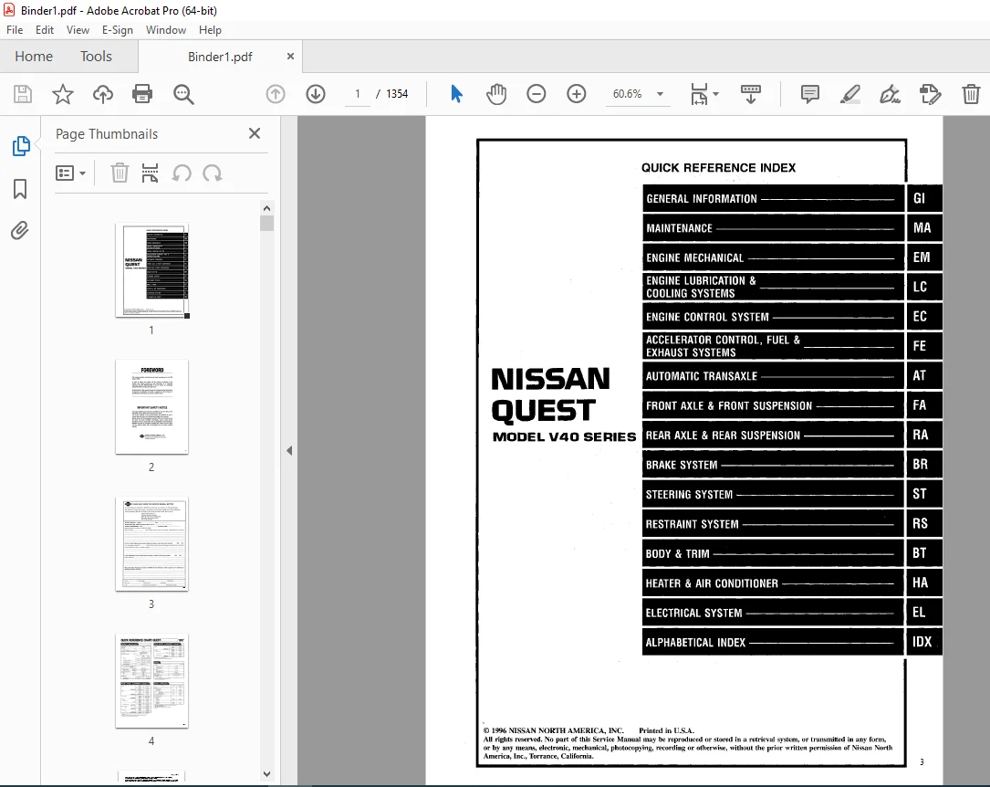
1997 NISSAN QUEST V40 Series Service Manual PDF DOWNLOAD
$24.95
1997 NISSAN QUEST V40 Series Service Manual PDF DOWNLOAD
Instant PDF Download
Available immediately
Save to Your Device
Download & keep forever
Antivirus Scanned
100% virus-free
Trusted Worldwide
175,000+ customers
Description
1997 NISSAN QUEST V40 Series Service Manual PDF DOWNLOAD
FILE DETAILS:
1997 NISSAN QUEST V40 Series Service Manual PDF DOWNLOAD
Language : English
Pages : 1354
downloadable : Yes
File type : PDF
IMAGES PREVIEW OF THE MANUAL:
TABLE OF CONTENTS:
1997 NISSAN QUEST V40 Series Service Manual PDF DOWNLOAD
fwd.............................................................................................   1
	QUICK REFERENCE INDEX.......................................................................   1
	FOREWORD....................................................................................   2
	GI - General Information....................................................................   0
	MA - Maintenance............................................................................   0
	EM - Engine Mechanical......................................................................   0
	LC - Engine Lubrication & Cooling Systems...................................................   0
	EC - Engine Control System..................................................................   0
	FE - Accelerator Control, Fuel & Exhaust Systems............................................   0
	AT - Automatic Transaxle ...................................................................   0
	FA - Front Axle & Front Suspension..........................................................   0
	RA - Rear Axle & Rear Suspension............................................................   0
	BR - Brake System...........................................................................   0
	ST - Steering System........................................................................   0
	RS - Restraint System.......................................................................   0
	BT - Body & Trim............................................................................   0
	HA - Heater & Air Conditioner...............................................................   0
	EL - Electrical System......................................................................   0
	IDX - Alphabetical Index....................................................................   1
	Foldout.....................................................................................   0
	Comment Sheet...............................................................................   3
	Quick Reference Chart.......................................................................   4
	GST Mode 6 - Test Value & Test Limit Chart..................................................   5
at..............................................................................................   6
	QUICK REFERENCE INDEX.......................................................................   0
	TABLE OF CONTENTS...........................................................................   6
	PREPARATION AND PRECAUTIONS.................................................................   8
		Special Service Tools...................................................................   8
		Commercial Service Tools................................................................  11
		Precautions for Supplemental Restraint System (SRS) "AIR BAG"...........................  12
		Precautions for On board Diagnostic (OBD) System of A/T and Engine......................  12
		Precautions.............................................................................  13
		Service Notice or Precautions...........................................................  14
	OVERALL SYSTEM..............................................................................  15
		A/T Electrical Parts Location...........................................................  15
		Circuit Diagram.........................................................................  16
		Wiring Diagram - A/T -..................................................................  17
		Cross-sectional View....................................................................  23
		Hydraulic Control Circuit...............................................................  24
		Shift Mechanism.........................................................................  25
		Control System..........................................................................  27
	ON BOARD DIAGNOSTIC SYSTEM DESCRIPTION......................................................  29
		Introduction............................................................................  29
		One or Two Trip Detection Logic.........................................................  29
			One Trip Detection Logic............................................................  29
			Two Trip Detection Logic............................................................  29
		Diagnostic Trouble Code (DTC)...........................................................  29
			HOW TO ERASE DTC (With CONSULT).....................................................  30
			HOW TO ERASE DTC (With GST).........................................................  31
			HOW TO ERASE DTC (No Tools).........................................................  31
		Self-diagnosis..........................................................................  32
			SELF-DIAGNOSTIC PROCEDURE (With CONSULT)............................................  32
			SELF-DIAGNOSTIC PROCEDURE (With GST)................................................  33
			SELF-DIAGNOSTIC PROCEDURE (No Tools)................................................  34
		Diagnosis by CONSULT....................................................................  38
	TROUBLE DIAGNOSES - Introduction............................................................  42
	TROUBLE DIAGNOSIS - Basic Inspection........................................................  47
		A/T Fluid Check.........................................................................  47
		Road Test...............................................................................  47
		Shift Schedule..........................................................................  58
	TROUBLE DIAGNOSIS - General Description.....................................................  60
		Diagnostic Trouble Code (DTC) Chart.....................................................  60
		Symptom Chart...........................................................................  62
		A/T Control Unit Terminals and Reference Values.........................................  65
	DTC P0705, Inhibitor, Overdrive Control and Throttle Position Switch........................  69
	DTC P0710, A/T Fluid Temperature Sensor and A/T Control Unit Power Source...................  74
	DTC P0720, Vehicle Speed Sensor - A/T (Revolution Sensor)...................................  77
	DTC P0725, Engine Speed Signal..............................................................  79
	DTC P0731, Improper Shifting to 1st Gear Position...........................................  81
	DTC P0732, Improper Shifting to 2nd Gear Position...........................................  84
	DTC P0733, Improper Shifting to 3rd Gear Position...........................................  87
	DTC P0734, Improper Shiftin to the 4th Gear Position or Improper Torque Converter Clutch....  90
	DTC P0740, Torque Converter Clutch Solenoid Valve...........................................  95
	DTC P0744, Improper Lock-up Operation.......................................................  98
	DTC P0745, Line Pressure Solenoid Valve..................................................... 103
	DTC P0750, Shift Solenoid Valve A........................................................... 106
	DTC P0755, Shift Solenoid Valve B........................................................... 109
	DTC P1705, Throttle Position Sensor......................................................... 112
	DTC P1760, Overrun Clutch Solenoid Valve.................................................... 114
	TROUBLE DIAGNOSIS FOR VHCL SPEED SEN-MTR.................................................... 117
	DIAGNOSTIC PROCEDURE FOR SYMPTOM............................................................ 119
		1. O/D OFF Indicator Lamp does Not Come On.............................................. 119
		2. Engine Cannot Be Started in "P" and "N" Position..................................... 120
		3. In "P" Position, Vehicle Moves Forward Or Backward When Pushed....................... 120
		4. In "N" Position, Vehicle Moves....................................................... 121
		5. Large Shock "N" - "R" Position....................................................... 122
		6. Vehicle Does Not Creep Backward in "R" Position...................................... 123
		7. Vehicle Does Not Creep Forward IN "D", "2" or "1" Position........................... 124
		8. Vehicle Cannot Be Started From D1.................................................... 125
		9. A/T Does Not Shift: D1 - D2 Or Does Not Kickdown: D4 - D2............................ 126
		10. A/T Does Not Shift: D2 - D3......................................................... 127
		11. A/T Does Not Shift: D3 - D4......................................................... 128
		12. A/T Does Not Perform Lock-up........................................................ 129
		13. A/T Does Not Hold Lock-up Condition................................................. 130
		14. Lock-up Is Not Released............................................................. 130
		15. Engine Speed Does Not Return to Idle (Light Braking D4 - D3)........................ 131
		16. Vehicle Does Not Start From D1...................................................... 132
		17. A/T Does Not Shift: D4 - D3, When Overdrive Control Switch ON - OFF................. 132
		18. A/T Does Not Shift: D3 - 22, When Selector Lever "D" - "2" Position................. 133
		19. A/T Does Not Shift 22 - 11, When Selector Lever "2" - "1" Position.................. 133
		20. Vehicle Does Not Decelerate By Engine Brake......................................... 134
	TROUBLE DIAGNOSES........................................................................... 135
		Final Check............................................................................. 135
			Stall Testing....................................................................... 135
			Pressure Testing.................................................................... 138
	TROUBLE DIAGNOSIS - A/T Shift Lock System................................................... 140
		Description............................................................................. 140
		Shift Lock System Electrical Parts Location............................................. 140
		Removal - Shift Lock Solenoid........................................................... 140
		Wiring Diagram - SHIFT - ............................................................... 141
		Diagnostic Procedure.................................................................... 142
		Shift Lock Rod.......................................................................... 144
		Component Check......................................................................... 145
	ON-VEHICLE SERVICE.......................................................................... 146
		Control Valve Assembly and Accumulator.................................................. 146
		Revolution Sensor Replacement........................................................... 147
		Inhibitor Switch Adjustment............................................................. 147
		Control Cable Adjustment................................................................ 148
		Position Indicator Adjustment........................................................... 148
		Differential Side Oil Seal Replacement.................................................. 148
	REMOVAL AND INSTALLATION.................................................................... 149
	MAJOR OVERHAUL.............................................................................. 151
		Oil Channel............................................................................. 154
		Location of Adjusting Shims, Needle Bearings, Thrust Washers and Snap Rings............. 155
	DISASSEMBLY................................................................................. 156
	REPAIR FOR COMPONENT PARTS.................................................................. 170
		Manual Shaft............................................................................ 170
		Oil Pump................................................................................ 172
		Control Valve Assembly.................................................................. 176
		Control Valve Upper Body................................................................ 184
		Control Valve Lower Body................................................................ 188
		Reverse Clutch.......................................................................... 190
		High Clutch............................................................................. 193
		Forward Clutch and Overrun Clutch....................................................... 197
		Low & Reverse Brake..................................................................... 203
		Rear Internal Gear, Forward Clutch Hub and Overrun Clutch Hub........................... 206
		Output Shaft, Idler Gear, Reduction Pinion Gear and Bearing Retainer.................... 210
		Band Servo Piston Assembly.............................................................. 215
		Final Drive............................................................................. 220
	ASSEMBLY.................................................................................... 224
		Assembly 1.............................................................................. 224
		Adjustment 1............................................................................ 224
			Differential Side Bearing Preload................................................... 224
			Reduction Pinion Gear Bearing Preload............................................... 226
			Output Shaft End Play............................................................... 228
		Assembly 2.............................................................................. 229
		Adjustment 2............................................................................ 235
			Total End Play...................................................................... 235
		Assembly 3.............................................................................. 237
	SERVICE DATA AND SPECIFICATIONS (SDS)....................................................... 243
br.............................................................................................. 250
	QUICK REFERENCE INDEX.......................................................................   0
	TABLE OF CONTENTS........................................................................... 250
	PRECAUTIONS AND PREPARATION................................................................. 251
		Precautions............................................................................. 251
		Commercial Service Tools................................................................ 252
	CHECK AND ADJUSTMENT........................................................................ 253
		Checking Brake Fluid Level.............................................................. 253
		Checking Brake Line..................................................................... 253
		Changing Brake Fluid.................................................................... 253
	AIR BLEEDING................................................................................ 254
		Bleeding Procedure...................................................................... 254
	BRAKE HYDRAULIC LINE........................................................................ 255
	CONTROL VALVE............................................................................... 257
		Dual Load Sensing Valve................................................................. 257
	BRAKE PEDAL AND BRACKET..................................................................... 260
		Removal and Installation................................................................ 260
		Inspection.............................................................................. 260
		Adjustment.............................................................................. 261
	MASTER CYLINDER............................................................................. 262
	BRAKE BOOSTER............................................................................... 265
	VACUUM HOSE................................................................................. 267
	FRONT DISC BRAKE............................................................................ 268
	REAR DRUM BRAKE............................................................................. 272
	PARKING BRAKE CONTROL....................................................................... 276
	ANTI-LOCK BRAKE SYSTEM...................................................................... 278
		Purpose................................................................................. 278
		Operation............................................................................... 278
		System Components....................................................................... 279
		System Description...................................................................... 279
		Removal and Installation................................................................ 280
			Front Wheel Sensor.................................................................. 280
			Rear Wheel Sensor................................................................... 280
			ABS Actuator........................................................................ 281
			Control Unit........................................................................ 283
			ABS Relays.......................................................................... 283
	TROUBLE DIAGNOSES........................................................................... 284
		How to Perform Trouble Diagnoses for Quick and Accurate Repair.......................... 284
		Preliminary Check....................................................................... 285
		Component Parts Location and Harness Layout............................................. 286
		Circuit Diagram......................................................................... 287
		Wiring Diagram - ABS -.................................................................. 288
		Self-diagnosis.......................................................................... 292
			Function............................................................................ 292
			Self-Diagnosis Procedure............................................................ 292
			How To Read Self-Daignostic Results (malfunction codes)............................. 293
			How To Erase Self-Diagnostic Results (Malfunction codes)............................ 293
			Malfunction Code/Symptom Chart...................................................... 294
		Ground Circuit Check.................................................................... 295
	TROUBLE DIAGNOSES FOR SELF-DIAGNOSTIC ITEM.................................................. 296
	TROUBLE DIAGNOSES FOR SYMPTOM............................................................... 306
	SERVICE DATA AND SPECIFICATIONS (SDS)....................................................... 314
bt.............................................................................................. 315
	QUICK REFERENCE INDEX.......................................................................   0
	TABLE OF CONTENTS........................................................................... 315
	PRECAUTIONS................................................................................. 316
		Supplemental Restraint System (SRS) "AIR BAG"........................................... 316
	GENERAL SERVICING........................................................................... 317
		Clip and Fastener....................................................................... 317
	BODY END.................................................................................... 320
		Body Front End.......................................................................... 320
			Removal - Front bumper assembly..................................................... 320
			Bumper Shock Absorber Inspection.................................................... 323
		Body Rear End and Opener................................................................ 324
			Removal - Rear bumper assembly...................................................... 324
			Bumper Shock Absorber Inspection - Rear............................................. 324
	DOOR........................................................................................ 327
		Front door.............................................................................. 327
		Sliding Door............................................................................ 328
		Rear Door............................................................................... 330
	INSTRUMENT PANEL............................................................................ 332
	INTERIOR TRIM............................................................................... 336
		Side and Floor Trim..................................................................... 336
		Roof Trim............................................................................... 340
	EXTERIOR.................................................................................... 342
		(1) Hood front sealing rubber........................................................... 343
		(2) (3) Hood rear sealing rubber and cowl top grille.................................... 343
		(4) Sun roof frame weatherstrip and sun roof lid weatherstrip........................... 343
		(5) Windshielf upper molding............................................................ 343
		(6) Windshield side molding............................................................. 343
		(7) Body side drip molding.............................................................. 344
		(8) Waist rail finisher................................................................. 344
		(9) Front door weatherstrip............................................................. 344
		(10) Sliding door weatherstrip.......................................................... 344
		(11) Sliding door lower seal............................................................ 344
		(12) Back door opening weatherstrip..................................................... 344
		(13) Luggage rack....................................................................... 345
		(14) Outside door molding............................................................... 346
		(15) Front door corner covers........................................................... 347
		(16) Side gurard molding................................................................ 347
	SEAT........................................................................................ 348
		Front Seat.............................................................................. 348
		Front Power Seat........................................................................ 349
		2nd Seat................................................................................ 350
		3rd Seat................................................................................ 352
	SUN ROOF.................................................................................... 357
	WINDSHIELD AND WINDOWS...................................................................... 360
		Windshield and Rear Window.............................................................. 361
		Repairing Water Leaks For Windshield.................................................... 361
		Side Window (1st)....................................................................... 362
		Side Window (2nd)....................................................................... 363
	MIRROR...................................................................................... 364
		Door Mirror............................................................................. 364
		Rearview Mirror......................................................................... 365
	BODY ALIGNMENT.............................................................................. 366
		Engine Compartment...................................................................... 367
		Underbody............................................................................... 369
ec.............................................................................................. 372
	QUICK REFERENCE INDEX.......................................................................   0
	TABLE OF CONTENTS........................................................................... 372
	DIAGNOSTIC TROUBLE CODE INDEX............................................................... 374
		Alphabetical & P No. Index for DTC...................................................... 374
	PRECAUTIONS AND PREPARATION................................................................. 375
		Special Service Tool.................................................................... 375
		Commercial Service Tool................................................................. 375
		Supplemental Restraint System (SRS) "AIR BAG............................................ 375
		Precautions for On Board Diagnostic (OBD) System of Engine and A/T...................... 376
		Engine Fuel & Emission Control System................................................... 377
		Precautions............................................................................. 378
	ENGINE AND EMISSION CONTROL OVERALL SYSTEM.................................................. 380
		Circuit Diagram......................................................................... 380
		System Diagram.......................................................................... 381
		ECCS Component Parts Location........................................................... 383
		Vacuum Hose Drawing..................................................................... 384
		System Chart............................................................................ 385
	ENGINE AND EMISSION BASIC CONTROL SYSTEM DESCRIPTION........................................ 386
		Multiport Fuel Injection (MFI) System................................................... 386
		Distributor Ignition (DI) System........................................................ 388
		Air Conditioning Cut Control............................................................ 389
		Fuel Cut Control........................................................................ 390
	EVAPORATIVE EMISSION SYSTEM................................................................. 391
		Description............................................................................. 391
		Inspection.............................................................................. 391
	POSITIVE CRANKCASE VENTILATION.............................................................. 393
		Description............................................................................. 393
		Inspection.............................................................................. 393
	BASIC SERVICE PROCEDURE..................................................................... 394
		Fuel Pressure Release................................................................... 394
		Fuel Pressure Check..................................................................... 394
		Fuel Pressure Regulator Check........................................................... 395
		Injector Removal and Installation....................................................... 395
		Fast Idle Cam (FIC) Inspection and Adjustment........................................... 396
		Idle Speed/Ignition Timing/Idle Mixture Ratio Adjustment................................ 397
	ON BOARD DIAGNOSTIC SYSTEM DESCRIPTION...................................................... 403
		Introduction............................................................................ 403
		Two Trip Detection  Logic............................................................... 403
		Emission-related Diagnostic Information................................................. 404
		Malfunction Indicator Lamp (MIL)........................................................ 414
		OBD System Operation Chart.............................................................. 418
		CONSULT................................................................................. 423
		Generic Scan Tool (GST)................................................................. 434
	TROUBLE DIAGNOSIS - Introduction............................................................ 436
		Introduction............................................................................ 436
		Diagnostic Worksheet.................................................................... 437
	TROUBLE DIAGNOSIS - Work Flow............................................................... 438
		Work Flow............................................................................... 438
		Description for Work Flow............................................................... 439
	TROUBLE DIAGNOSIS - Basic Insepction........................................................ 440
		Basic Inspection........................................................................ 440
	TROUBLE DIAGNOSIS - General Description..................................................... 442
		Diagnostic Trouble Code (DTC) Chart..................................................... 442
		Fail-Safe Chart......................................................................... 443
		Symptom Matrix Chart.................................................................... 444
		CONSULT Reference Value in Data Monitor Mode............................................ 447
		Major Sensor Reference Graph in Data Monitor Mode....................................... 449
		ECM Terminals and Reference Value....................................................... 451
	TROUBLE DIAGNOSIS FOR POWER SUPPLY.......................................................... 457
		Main Power Supply and Ground Circuit.................................................... 457
	DTC P0100, Mass Air Flow Sensor (MAFS)...................................................... 461
	DTC P0110, Intake Air Temperature Sensor.................................................... 467
	DTC P0115, Engine Coolant Temperature Sensor (ECTS)......................................... 472
	DTC P0120, Throttle Position Sensor......................................................... 477
	DTC P0125, Engine Coolant Temperature (ECT) Sensor.......................................... 483
	DTC P0130, Front Heated Oxygen Sensor (Front HO2S).......................................... 488
	DTC P0130, Closed Loop Control.............................................................. 493
	DTC P0135, Front Heated Oxygen Sensor Heater................................................ 494
	DTC P0136, Rear Heated Oxygen Sensor (Rear HO2S)............................................ 498
	DTC P0141, Rear Heated Oxygen Sensor Heater................................................. 502
	DTC P0171, Fuel Injection System Function (Lean side)....................................... 507
	DTC P0172, Fuel Injection System Function (Rich side)....................................... 512
	DTC P0300 - P0306, No. 6 - 1 Cylinder Misfire, Multiple Cylinder Misfire.................... 517
	DTC P0325, Knock Sensor (KS)................................................................ 521
	DTC P0335, Crankshaft Position Sensor (CKPS) (OBD).......................................... 524
	DTC P0340, Camshaft Position Sensor (CMPS).................................................. 529
	DTC P0400, EGR Function..................................................................... 535
	DTC P0402, EGRC-BPT Valve Function.......................................................... 544
	DTC P0420, Three Way Catalyst Function...................................................... 546
	DTC P0500, Vehicle Speed Sensor (VSS)....................................................... 549
	DTC P0505, Idle Air Control Valve (IACV) - Auxiliary Air Control (AAC) Valve................ 553
	DTC P0600, A/T Control...................................................................... 558
	DTC P0605, Engine Control Module (ECM)-ECCS Control Module.................................. 561
	DTC P0705, Park/Neutral Position Switch..................................................... 563
	DTC P1320, Ignition Signal.................................................................. 567
	DTC P1336, Crankshaft Position Sensor (CKPS) (OBD) (COG).................................... 573
	DTC P1400, EGR Valve and EVAP Canister Purge Control Solenoid Valve......................... 578
	DTC P1401, EGR Temperature Sensor........................................................... 583
	DTC P1605, A/T Diagnosis Communication Line................................................. 589
	DTC P1900, Cooling Fan...................................................................... 592
	TROUBLE DIAGNOSIS FOR NON-DETECTABLE ITEMS.................................................. 604
		Injector................................................................................ 604
		Start Signal............................................................................ 607
		Fuel Pump............................................................................... 610
		Power Steeing Oil Pressure Switch....................................................... 616
		IACV-FICD Solenoid Valve/Air Conditioning System Input.................................. 620
		Air Conditioner High Pressure Switch.................................................... 626
		MIL & Data Link Connectors.............................................................. 629
	SERVICE DATA AND SPECIFICATIONS............................................................. 631
		General Specifications.................................................................. 631
		Inspection and Adjustment............................................................... 631
el.............................................................................................. 633
	QUICK REFERENCE INDEX.......................................................................   0
	TABLE OF CONTENTS........................................................................... 633
	PRECAUTIONS................................................................................. 636
		Supplemental Restraint System (SRS) "AIR BAG"........................................... 636
	HARNESS CONNECTOR........................................................................... 637
	STANDARDIZED RELAY.......................................................................... 638
	POWER SUPPLY ROUTING........................................................................ 640
		Schematic............................................................................... 640
		Wiring Diagram - POWER - ............................................................... 641
		Fuse.................................................................................... 649
		Fusible Link............................................................................ 649
		Circuit Breaker......................................................................... 649
	GROUND DISTRIBUTION......................................................................... 651
	BATTERY..................................................................................... 654
		How to Handle Battery................................................................... 654
		Service Data and Specifications (SDS)................................................... 657
	STARTING SYSTEM............................................................................. 658
		System Description...................................................................... 658
		Wiring Diagram - START -................................................................ 660
		Starter................................................................................. 662
		Removal and Installation................................................................ 663
		Pinion/Clutch Check..................................................................... 663
		Service Data and Specifications (SDS)................................................... 663
	CHARGING SYSTEM............................................................................. 664
		System Description...................................................................... 664
		Wiring Diagram - CHARGE -............................................................... 665
		Trouble Diagnoses....................................................................... 666
			With Ic Regulator................................................................... 666
			Malfunction Indicator............................................................... 666
	CHARGING SYSTEM - Generator -............................................................... 667
		Construction............................................................................ 667
		Removal and Installation................................................................ 667
		Diode Check............................................................................. 668
		Assembly................................................................................ 668
		Service Data and Specifications (SDS)................................................... 669
	COMBINATION SWITCH.......................................................................... 670
		Combination Switch/Check................................................................ 670
		Combination Switch/Replacement.......................................................... 671
		Steering Switch/Check................................................................... 672
	HEADLAMP.................................................................................... 673
		System Description (For USA)............................................................ 673
		Schematic (For USA)..................................................................... 674
		Wiring Diagram (For USA) - H/LAMP -..................................................... 676
		Trouble Diagnoses (For USA)............................................................. 678
		System Description (For Canada)......................................................... 680
		Operation (Daytime light system for Canada)............................................. 682
		Schematic (for Canada).................................................................. 683
		Wiring Diagram (For Canada) - DTRL -.................................................... 684
		Trouble Diagnoses (For Canada).......................................................... 687
		Bulb Replacement........................................................................ 689
		Bulb Specifications..................................................................... 689
		Aiming Adjustment....................................................................... 689
	AUTOLAMP.................................................................................... 691
		System Description...................................................................... 691
		Trouble Diagnosis....................................................................... 692
	EXTERIOR LAMP............................................................................... 696
		Back-up Lamp/Wiring Diagram - BACK/L -.................................................. 696
		Parking, License, Tail and Stop Lamps/Wiring Diagram - TAIL/L -......................... 698
		Turn Signal and Hazard Warning Lamps/System Description................................. 700
		Turn Signal and Hazard Warning Lamps/Wiring Diagram - TURN -............................ 702
		Turn Signal and Hazard Warning Lamps/Trouble Diagnoses.................................. 704
		Combination Flasher Unit Check.......................................................... 704
		Cornering Lamp/System Description....................................................... 705
		Cornering Lamp/Wiring Diagram - CORNER -................................................ 706
		Bulb Specifications..................................................................... 707
	TRAILER TOW................................................................................. 708
		System Description...................................................................... 708
		Wiring Diagram - T/TOW -................................................................ 709
		Trouble Diagnoses....................................................................... 710
	INTERIOR LAMP............................................................................... 711
		Illumination/System Description......................................................... 711
		Illumination/Schematic.................................................................. 713
		Illumination/Wiring Diagram - ILL -..................................................... 714
		Interior, MAP, Personal, Step and Tailgate Lamps/System Description..................... 718
		Interior, MAP, Personal, Step and Tailgate Lamps/Schematic.............................. 721
		Interior, MAP, Personal, Step and Tailgate Lamps/Wiring Diagram - INT/L ................ 722
		Bulb Specifications..................................................................... 725
	METERS AND GAUGES........................................................................... 726
		System Description...................................................................... 726
		Combination Meter....................................................................... 727
		Speedometer, Tachometer, Temp. and Fuel Gauges/Wiring Diagram - METER -................. 728
		Inspection/Water Temperature Gauge...................................................... 729
		Inspection/Fuel Gauge................................................................... 730
		Inspection/Tachometer................................................................... 731
		Inspection/Speedometer and Vehicle Speed Sensor......................................... 732
		Inspection/Speedometer and Fuse......................................................... 733
		Fuel Tank Gauge Unit Check.............................................................. 734
		Thermal Transmitter Check............................................................... 734
		Vehicle Speed Sensor Signal Check....................................................... 734
	WARNING LAMPS............................................................................... 735
		System Description...................................................................... 735
		Schematic............................................................................... 737
		Wiring Diagram - WARN -................................................................. 738
		Low Fuel Level Warning Lamp............................................................. 742
		Oil Pressure Switch Check............................................................... 742
		Diode Check............................................................................. 742
	WARNING CHIME............................................................................... 743
		System Description...................................................................... 743
		Warning Diagram - CHIME -............................................................... 744
		Trouble Diagnoses....................................................................... 745
	WIPER AND WASHER............................................................................ 751
		Front Wiper and Washer/System Description............................................... 751
		Front Wiper and Washer/Wiring Diagram - WIPER -......................................... 752
		Front Wiper and Washer/Trouble Diagnoses................................................ 753
		Front Wiper............................................................................. 755
		Rear Wiper and Washer (Except for Glass Hatch Model) /System Description................ 756
		Rear Wiper and Washer (Except for Glass Hatch Model)/Wiring Diagram - WIP/R -........... 757
		Rear Wiper and Washer (For Glass Hatch Model)/System Description........................ 758
		Rear Wiper and Washer (For Glass Hatch Model/Wiring Diagram - WIP/HR - ................. 759
		Rear Wiper.............................................................................. 760
		Washer Fluid and Check Valve............................................................ 761
	HORN AND LIGHTER............................................................................ 762
		Wiring Diagram - HORN -................................................................. 762
	REAR WINDOW DEFOGGER........................................................................ 763
		System Description...................................................................... 763
		Wiring Diagram - DEF -.................................................................. 764
		Trouble Diagnoses....................................................................... 765
		Filament Check.......................................................................... 766
		Filament Repair......................................................................... 767
	AUDIO....................................................................................... 769
		System Description...................................................................... 769
		Schematic............................................................................... 770
		Wiring Diagram - AUDIO -................................................................ 772
		Trouble Diagnoses....................................................................... 776
	POWER ANTENNA............................................................................... 779
		System Description...................................................................... 779
		Wiring Diagram - P/ANT -................................................................ 780
		Trouble Diagnoses....................................................................... 781
		Location of Antenna..................................................................... 782
		Antenna Rod Replacement................................................................. 782
	ELECTRIC SUNROOF............................................................................ 784
		System Description...................................................................... 784
		Wiring Diagram - SROOF -................................................................ 785
	POWER DOOR MIRROR........................................................................... 786
		Wiring Diagram - MIRROR -............................................................... 786
	HEATED MIRROR............................................................................... 787
		Wiring Diagram - H/MIRR -............................................................... 787
	POWER SEAT.................................................................................. 788
		Power Seat/Wiring Diagram - SEAT -...................................................... 788
	AUTOMATIC SPEED CONTROL DEVICE (ASCD)....................................................... 790
		Component Parts and Harness Connector Location.......................................... 790
		System Description...................................................................... 791
		Schematic............................................................................... 793
		Wiring Diagram - ASCD -................................................................. 794
		Trouble Diagnoses....................................................................... 799
	POWER WINDOW................................................................................ 811
		Component Layout........................................................................ 811
		System Description...................................................................... 812
		Wiring Diagram - WINDOW -............................................................... 816
		Trouble Diagnoses....................................................................... 818
	POWER DOOR LOCK............................................................................. 819
		System Description...................................................................... 819
		Schematic............................................................................... 822
		Wiring Diagram - D/LOCK -............................................................... 824
		Trouble Diagnoses....................................................................... 828
	MULTI-REMOTE CONTROL SYSTEM................................................................. 835
		System Description...................................................................... 835
		Schematic............................................................................... 838
		Wiring Diagram - MULTI -................................................................ 839
		Trouble Diagnoses....................................................................... 843
		Replacing Remote Controller or Multi-Remote Control Unit................................ 849
	THEFT WARNING SYSTEM........................................................................ 850
		Component Parts and Harness Connector Location.......................................... 850
		System Description...................................................................... 852
		Schematic............................................................................... 856
		Wiring Diagram - THEFT -................................................................ 857
		Trouble Diagnosis....................................................................... 866
	SMART ENTRANCE CONTROL UNIT................................................................. 882
		Description............................................................................. 882
		Input/Output Operation Signal........................................................... 883
	LOCATION OF ELECTRICAL UNITS................................................................ 885
		Engine Compartment...................................................................... 885
		Passenger Compartment................................................................... 886
		Luggage Compartemnt..................................................................... 887
	HARNESS LAYOUT.............................................................................. 888
		How To Read Harness Layout.............................................................. 888
		Outline................................................................................. 889
		Main Harness............................................................................ 890
		Body Harness............................................................................ 894
		Engine Control Harness.................................................................. 896
		Engine Control Sub-Harness.............................................................. 899
		Engine Room Harness..................................................................... 900
		A/T Control Harness..................................................................... 903
		Room Lamp Harness....................................................................... 904
		Air Bag Harness......................................................................... 905
		Front Door Harness...................................................................... 906
		Back Door Harness....................................................................... 907
		Sliding Door Harness.................................................................... 908
	SUPER MULTIPLE JUNCTION (SMJ)...............................................................   2
	JOINT CONNECTOR (J/D).......................................................................   4
	FUSE BLOCK/FUSE AND FUSIBLE LINK BOX........................................................   0
	CONTROL UNITS...............................................................................   1
em.............................................................................................. 909
	QUICK REFERENCE INDEX.......................................................................   0
	TABLE OF CONTENTS........................................................................... 909
	PRECAUTIONS................................................................................. 910
		Parts Requiring Angular Tightening...................................................... 910
		Liquid Gasket Application Procedure..................................................... 910
	PREPARATION................................................................................. 911
		Special Service Tools................................................................... 911
		Commercial Service Tools................................................................ 912
	OUTER COMPONENT PARTS....................................................................... 913
	COMPRESSION PRESSURE........................................................................ 915
		Measurement of Compression Pressure..................................................... 915
	OIL PAN..................................................................................... 916
		Removal................................................................................. 916
		Installation............................................................................ 917
	TIMING BELT................................................................................. 919
		Removal................................................................................. 920
		Inspection.............................................................................. 922
		Installation............................................................................ 923
	OIL SEAL REPLACEMENT........................................................................ 926
	CYLINDER HEAD............................................................................... 928
		Removal................................................................................. 929
		Disassembly............................................................................. 932
		Inspection.............................................................................. 933
		Assembly................................................................................ 940
		Installation............................................................................ 941
	ENGINE REMOVAL.............................................................................. 946
		Removal................................................................................. 946
		Installation............................................................................ 947
	CYLINDER BLOCK.............................................................................. 948
		Disassembly............................................................................. 949
		Inspection.............................................................................. 949
		Assembly................................................................................ 956
	SERVICE DATA AND SPECIFICATIONS (SDS)....................................................... 959
		General Specifications.................................................................. 959
		Inspection and Adjustment............................................................... 959
fa.............................................................................................. 966
	QUICK REFERENCE INDEX.......................................................................   0
	TABLE OF CONTENTS........................................................................... 966
	PRECAUTIONS AND PREPARATION................................................................. 967
		Precautions............................................................................. 967
		Special Service Tools................................................................... 967
		Commercial Service Tools................................................................ 968
	FRONT AXLE AND FRONT SUSPENSION............................................................. 969
	ON-VEHICLE SERVICE.......................................................................... 970
		Front Axle and Front Suspension Parts................................................... 970
		Front Wheel Bearing..................................................................... 971
		Front Wheel Alignment................................................................... 971
		Drive Shaft............................................................................. 973
	FRONT AXLE.................................................................................. 974
		Wheel Hub and Knuckle................................................................... 975
		Drive Shaft............................................................................. 978
	FRONT SUSPENSION............................................................................ 986
		Coil Spring and Strut Assembly.......................................................... 987
		Stabilizer Bar.......................................................................... 988
		Transverse Link and Transverse Link Gusset.............................................. 989
		Lower Ball Joint........................................................................ 989
	SERVICE DATA AND SPECIFICATIONS (SDS)....................................................... 991
		General Specifications.................................................................. 991
		Inspection and Adjustment............................................................... 992
fe.............................................................................................. 993
	QUICK REFERENCE INDEX.......................................................................   0
	TABLE OF CONTENTS........................................................................... 993
	ACCELERATOR CONTROL SYSTEM.................................................................. 994
		Adjusting Accelerator Wire.............................................................. 994
	FUEL SYSTEM................................................................................. 995
		Fuel Tank............................................................................... 995
		Fuel Pump and Gauge..................................................................... 997
	EXHAUST SYSTEM.............................................................................. 998
foldout.........................................................................................1000
	QUICK REFERENCE INDEX.......................................................................   0
	FUSE BLOCK/FUSE AND FUSIBLE LINK BOX........................................................1000
	CONTROL UNITS...............................................................................1001
	SUPER MULTIPLE JUNCTION (SMJ)...............................................................1002
		INSTALLATION............................................................................1002
		Terminal Arrangement....................................................................1003
	JOINT CONNECTOR (J/C).......................................................................1004
		Location................................................................................1004
	ELECTRICAL SYSTEM........................................................................... 275
gi..............................................................................................1005
	QUICK REFERENCE INDEX.......................................................................   0
	TABLE OF CONTENTS...........................................................................1005
	PRECAUTIONS.................................................................................1006
		Precautions for Supplemental Restraint System (SRS) "AIR BAG"...........................1006
		General Precautions.....................................................................1007
		Precautions for Engine Oils.............................................................1009
		Precautions for Multiport Fuel Injection System or ECCS Engine..........................1010
		Precautions for Three Way Catalyst......................................................1010
		Precautions for Fuel....................................................................1010
		Precautions for Air Conditioning........................................................1010
	HOW TO USE THIS MANUAL......................................................................1011
	HOW TO READ WIRING DIAGRAMS.................................................................1013
		Sample/Wiring Diagram - EXAMPL -........................................................1013
		Description.............................................................................1015
		Wiring Diagram Codes (Cell Codes).......................................................1021
	HOW TO PERFORM EFFICIENT DIAGNOSIS FOR AN ELECTRICAL INCIDENT...............................1022
		Work Flow...............................................................................1022
		Incident Simulation Tests...............................................................1023
		Circuit Inspection......................................................................1027
	HOW TO FOLLOW FLOW CHART IN TROUBLE DIAGNOSES...............................................1034
		How To Follow This Flowchart............................................................1035
	CONSULT CHECKING SYSTEM.....................................................................1038
		Function and System Application.........................................................1038
		Lithium Battery Replacement.............................................................1038
		Checking Equipment......................................................................1038
	IDENTIFICATION INFORMATION..................................................................1039
		Model Variation.........................................................................1039
		Identification Number...................................................................1040
		Dimensions..............................................................................1041
		Wheels and Tires........................................................................1041
	LIFTING POINTS AND TOW TRUCK TOWING.........................................................1042
		Preparation.............................................................................1042
		Board-on Lift...........................................................................1043
		Garage Jack and Safety Stand............................................................1043
		2-pole Lift.............................................................................1043
		Tow Truck Towing........................................................................1044
	TIGHTENING TORQUE OF STANDARD BOLTS.........................................................1045
	SAE J1930 TERMINOLOGY LIST..................................................................1046
ha..............................................................................................1050
	QUICK REFERENCE INDEX.......................................................................   0
	TABLE OF CONTENTS...........................................................................1050
	MANUAL AND AUTO.............................................................................1052
		PRECAUTIONS AND PREPARATION.............................................................1052
			Precautions for Supplement Restraint System (SRS) "AIR BAG".........................1052
			Identification......................................................................1052
			Precautions for Working with R-134a.................................................1053
			Precautions for Working with Refrigerants...........................................1053
			Precautions for Refrigerant Connections.............................................1054
			Precautions for Servicing Compressor................................................1055
			R-134a Service Tools and Equipment..................................................1056
			Commercial Service Tools............................................................1058
			Precautions for Service Equipment...................................................1060
		DESCRIPTION.............................................................................1062
			Refrigeration Cycle.................................................................1062
			Component Layout....................................................................1064
	MANUAL......................................................................................1065
		DESCRIPTION.............................................................................1065
			Control Operation...................................................................1065
			Discharge Air Flow..................................................................1066
		TROUBLE DIAGNOSES.......................................................................1068
			How to Perform Trouble Diagnoses for Quick and Accurate Repair......................1068
			Operational Check...................................................................1069
			Symptom Chart.......................................................................1072
			Preliminary Check...................................................................1073
			Performance Test Diagnoses..........................................................1080
			Harness Layout......................................................................1084
			Circuit Diagram.....................................................................1087
			Wiring Diagram - A/C, M -...........................................................1088
			Main Power Supply and Ground circuit Check..........................................1093
			Diagnostic Procedure................................................................1095
			Electrical Components Inspection....................................................1114
			Control Linkage Adjustment..........................................................1116
	AUTO........................................................................................1118
		DESCRIPTION.............................................................................1118
			Introduction........................................................................1118
			Features............................................................................1118
			Control Operation...................................................................1119
			Discharge Air Flow..................................................................1121
		TROUBLE DIAGNOSES.......................................................................1123
			How to Perform Trouble Diagnoses for Quick and Accurate Repair......................1123
			Operational Check...................................................................1124
			Symptom Chart.......................................................................1127
			Self-diagnosis......................................................................1128
			Preliminary Check...................................................................1130
			Performance Test Diagnoses..........................................................1137
			Harness Layout......................................................................1140
			Circuit Diagram.....................................................................1144
			Wiring Diagram - A/C, A -...........................................................1145
			Main Power Supply and Ground Circuit Check..........................................1150
			Diagnostic Procedure................................................................1152
			Electrical Components Inspection....................................................1180
			Control Linkage Adjustment..........................................................1182
		SYSTEM DESCRIPTION......................................................................1184
			Overview of Control System..........................................................1184
			Control System Input Components.....................................................1185
			Control System Electronic Automatic Temperature Control Unit (EATC nit).............1187
			Control System Output Components....................................................1188
	MANUAL AND AUTO.............................................................................1197
		SERVICE PROCEDURES......................................................................1197
			Checking Refrigerant Leaks..........................................................1197
			R-134a Service Procedure............................................................1200
			Compressor Lubricant Quantity.......................................................1202
			Refrigerant Lines...................................................................1204
			Compressor (Ford Model FS-10).......................................................1206
			Clutch Hub and Pulley...............................................................1207
			Magnet Clutch Coil..................................................................1209
			Shaft Seal..........................................................................1210
			Belt Tension........................................................................1212
			Fast Idle Control Device (FICD).....................................................1212
			Front Heater Core...................................................................1212
			Front Evaporator Core...............................................................1214
			Rear Heater Core and Evaporator Core................................................1215
			Fan Switch and Illumination Bulbs...................................................1216
			Spring Lock Coupling................................................................1218
		SERVICE DATA AND SPECIFICATIONS (SDS)...................................................1220
			General Specifications..............................................................1220
			Inspection and Adjustment...........................................................1220
idx.............................................................................................1221
	QUICK REFERENCE INDEX.......................................................................   0
	TABLE OF CONTENTS...........................................................................1221
lc..............................................................................................1229
	QUICK REFERENCE INDEX.......................................................................   0
	TABLE OF CONTENTS...........................................................................1229
	PRECAUTIONS.................................................................................1230
		Supplemental Restraint System (SRS) "AIR BAG"...........................................1230
		Liquid Gasket Application Procdure......................................................1230
	PREPARATION.................................................................................1231
		Special Service Tools...................................................................1231
	ENGINE LUBRICATION SYSTEM...................................................................1232
		Lubrication Circuit.....................................................................1232
		Oil Pressure Check......................................................................1233
		Oil Pump................................................................................1233
	ENGINE COOLING SYSTEM.......................................................................1237
		Cooling Circuit.........................................................................1237
		System Check............................................................................1237
		Water Pump..............................................................................1239
		Thermostat..............................................................................1241
		Radiator................................................................................1243
		Cooling Fan Control System..............................................................1244
	SERVICE DATA AND SPECIFICATIONS (SDS).......................................................1245
		Engine Lubrication System...............................................................1245
		Engine Cooling System...................................................................1245
ma..............................................................................................1246
	QUICK REFERENCE INDEX.......................................................................   0
	TABLE OF CONTENTS...........................................................................1246
	PRECAUTIONS AND PREPARATION.................................................................1247
		Supplemental Restraint System (SRS) "AIR BAG"...........................................1247
	GENERAL MAINTENANCE.........................................................................1248
	PERIODIC MAINTENANCE........................................................................1250
		Schedule 1..............................................................................1251
		Schedule 2..............................................................................1252
	RECOMMENDED FLUIDS AND LUBRICANTS...........................................................1253
		Fluids and Lubricants...................................................................1253
		SAE Viscosity Number....................................................................1254
		Antifreeze Coolant Mixture Ratio........................................................1254
	ENGINE MAINTENANCE..........................................................................1255
		Checking Drive Belts....................................................................1255
		Changin Engine Coolant..................................................................1256
		Checking Fuel Lines.....................................................................1261
		Changing Fuel Filter....................................................................1261
		Changing Air Cleaner Filter.............................................................1262
		Changing Engine Oil.....................................................................1262
		Changing Oil Filter.....................................................................1263
		Changing Spark Plugs....................................................................1264
		Checking EVAP Vapor Purge Lines.........................................................1264
	CHASSIS AND BODY MAINTENANCE................................................................1265
		Checking Exhaust System.................................................................1265
		Checking A/T Fluid......................................................................1265
		Changing A/T Fluid......................................................................1266
		Checking Brake Fluid Level and Leaks....................................................1266
		Checking Brake Lines and Cables.........................................................1266
		Checking Disc Brake.....................................................................1266
		Checking Drum Brake.....................................................................1267
		Balancing Wheels........................................................................1268
		Tire Rotation...........................................................................1268
		Checking Steering Gear and Linkage......................................................1268
		Checking Power Steering Fluid and Lines.................................................1268
		Lubricating Hood Latches, Locks, Hinges, Sliding Door Rollers and Links.................1269
		Checking Seat Belts, Buckles, Retractors, Anchors and Adjusters.........................1270
	SERVICE DATA AND SPECIFICATIONS (SDS).......................................................1271
		Engine Maintenance......................................................................1271
		Chassis and Body Maintenance............................................................1271
ra..............................................................................................1272
	QUICK REFERENCE INDEX.......................................................................   0
	TABLE OF CONTENTS...........................................................................1272
	PRECAUTIONS AND PREPARATION.................................................................1273
		Precautions.............................................................................1273
		Commercial Service Tools................................................................1273
	REAR SUSPENSION SYSTEM......................................................................1274
	ON-VEHICLE SERVICE..........................................................................1275
		Rear Axle and Rear Suspension Parts.....................................................1275
		Rear Wheel Hub Bearing..................................................................1275
		Rear Wheel Alignment....................................................................1276
	REAR AXLE...................................................................................1277
		Wheel Hub...............................................................................1277
	REAR SUSPENSION AND AXLE....................................................................1279
		Removal and Installation................................................................1279
	REAR SUSPENSION.............................................................................1280
		Leaf Spring.............................................................................1281
		Shock Absorber..........................................................................1283
		Stabilizer Bar..........................................................................1283
	SERVICE DATA AND SPECIFICATIONS (SDS).......................................................1285
		General Specifications..................................................................1285
		Inspection and Adjustment...............................................................1286
rs..............................................................................................1287
	QUICK REFERENCE INDEX.......................................................................   0
	TABLE OF CONTENTS...........................................................................1287
	PRECAUTIONS.................................................................................1288
		Supplemental Restraint System (SRS) "AIR BAG"...........................................1288
	SEAT BELTS..................................................................................1289
		Front Seat Belt.........................................................................1290
		Rear Seat Belts.........................................................................1292
		Built-In Child Seat.....................................................................1294
	SUPPLEMENTAL RESTRAINT SYSTEM (SRS).........................................................1296
		Precautions for SRS "Air Bag" Service...................................................1296
		Special Service Tools...................................................................1296
		Description.............................................................................1297
		SRS Component Parts Location............................................................1297
		Maintenance Items.......................................................................1298
		Diagnosis Sensor Unit...................................................................1299
			Removal And Installation............................................................1299
		Driver Air Bag Module and Spiral Cable..................................................1301
			Removal.............................................................................1301
			Installation........................................................................1302
		Front Passenger Air Bag Module..........................................................1303
			Removal.............................................................................1303
			Installation........................................................................1304
		Disposal of Air Bag Module..............................................................1305
	TROUBLE DIAGNOSES - Supplemental Restraint System (SRS).....................................1309
		How to Perform Trouble Diagnoses for Quick and Accurate Repair..........................1309
		Schematic...............................................................................1311
		Wiring Diagram - SRS -..................................................................1312
		Self-diagnosis..........................................................................1314
			Diagnostic Procedures...............................................................1314
		Trouble Diagnoses for Air Bag Warning Lamp..............................................1327
			Diagnostic Procedures...............................................................1327
	COLLISION DIAGNOSIS.........................................................................1329
st..............................................................................................1330
	QUICK REFERENCE INDEX.......................................................................   0
	TABLE OF CONTENTS...........................................................................1330
	PRECAUTIONS AND PREPARATION.................................................................1331
		Supplemental Restraint System (SRS) "AIR BAG"...........................................1331
		Special Service Tools...................................................................1331
		Commercial Service Tool.................................................................1333
	ON-VEHICLE SERVICE..........................................................................1334
		Checking and Adjusting Drive Belts......................................................1334
		Checking Fluid Level....................................................................1334
		Checking Fluid Leakage..................................................................1334
		Bleeding Hydraulic System...............................................................1334
		Checking Sheering Wheel Turning Force (For power steering)..............................1335
		Checking Steering Wheel Play............................................................1335
		Checking Neutral Position on Steering Wheel.............................................1336
		Checking Front Wheel Turning Angle......................................................1336
		Checking Gear Housing Movement..........................................................1336
		Checking Hydraulic System...............................................................1336
	STEERING WHEEL AND STEERING COLUMN..........................................................1338
		Steering Wheel..........................................................................1338
		Turn signal cancel cam..................................................................1339
		Steering Column.........................................................................1340
		Disassembly and Assembly................................................................1341
		Inspection..............................................................................1343
	POWER STEERING GEAR AND LINKAGE.............................................................1344
		Removal and Installation................................................................1344
		Disassembly.............................................................................1347
		Inspection..............................................................................1347
		Assembly................................................................................1348
	POWER STEERING OIL PUMP.....................................................................1350
		Pre-disassembly Inspection..............................................................1350
		Inspection..............................................................................1351
		Disassembly.............................................................................1351
		Assembly................................................................................1351
	SERVICE DATA AND SPECIFICATIONS (SDS).......................................................1353
		General Specifications..................................................................1353
		Inspection and Adjustment...............................................................1353
Need help? Contact: [email protected]
https://vimeo.com/853579826?share=copy
DESCRIPTION:
1997 NISSAN QUEST V40 Series Service Manual PDF DOWNLOAD
FOREWORD
- This manual contains maintenance and repair procedures for the 1997 Nissan QUEST.
- In order to assure your safety and the efficient functioning of the vehicle, this manual should be read thoroughly.
- It is especially important that the PRECAUTIONS in the GI section be completely understood before starting any repair task.
- All information in this manual is based on the latest product information at the time of publication. The right is reserved to make changes in specifications and methods at any time without notice.
PLEASE NOTE:
- This is the same manual used by the dealers to diagnose and troubleshoot your vehicle
- You will be directed to the download page as soon as the purchase is completed. The whole payment and downloading process will take anywhere between 2-5 minutes
- Need any other service / repair / parts manual, please feel free to contact [email protected] . We still have 50,000 manuals unlisted
G.P