1998 AC ELECTRO-MOTOR CRUISE SYSTEM Service Manual
Original price was: $69.95.$25.95Current price is: $25.95.
1998 AC ELECTRO-MOTOR CRUISE SYSTEM Service Manual – PDF DOWNLOAD
Description
1998 AC ELECTRO-MOTOR CRUISE SYSTEM Service Manual – PDF DOWNLOAD
Questions? Email us: [email protected]
IMAGE PREVIEW:


DESCRIPTION:
1998 AC ELECTRO-MOTOR CRUISE SYSTEM Service Manual – PDF DOWNLOAD
- To reduce the chance of personal injury and/or property damage, the following instructions must be carefully observed: Proper service and repair are important to the safety of the service technician and the safe, reliable operation of all motor vehicles.
- If part replacement is necessary, the part must be replaced with one of the same part number or with an equivalent part. Do not use a replacement part of lesser quality. The service procedures recommended and described in this service manual are effective methods of performing service and repair. Some of these procedures require the use of tools specially designed for the purpose.
- Accordingly, anyone who intends to use a replacement part, service procedure or tool, which is not recommended by the vehicle manufacturer, must first determine that neither his safety or safe operation of the vehicle will be jeopardized by the replacement part, service procedure or tool selected.
- It is important to note that this manual contains various “cautions” and “notices” that must be carefully observed in order to reduce the risk of personal injury during service or repair, or the possibility that improper service or repair may damage the vehicle or render it unsafe.
- It is also important to understand that these “cautions” and “notices” are not exhaustive, because it is impossible to warn of all the possible hazardous consequences that might result from failure to follow these instructions.
TABLE OF CONTENTS:
1998 AC ELECTRO-MOTOR CRUISE SYSTEM Service Manual – PDF DOWNLOAD
Cruise Control Module………………………………………. . . . 3
2-Wheel Drive Speed Sensor Location:
Mode Control Switches on Turn Signal Lever. . . . . . . 4
Transmission………………………………………………….. . . 1 1
Internal Transmission Speed Sensor………………….. . . . 6
Chart: Road Test of Cruise System ………………….. . . 14
Combination Cruise/Stop Light/ Voltmeter Hookup……………………………………………… . . 15
Converter Clutch S w itch ………………………………… . . . 6
Cruise Mode Switch Connector (C 3 A !……………… . . 15
Plunger Type Cruise Release Switch ………………… . . . 7
GMT-400 Cruise Diagnostic C h a rt…………………….. . . 16
Cruise Control M o dule………………………………………. . . . 7
Electro-Motor Cruise System Circuit Schematic . . . . 18
Block Diagram, Electro-Motor Cruise System . . . . . 8
Schematic Symbol Explanation…………………………. . . 19
Installation on LB4 (4.3L), L03 (5.0L), Cruise Module Connector Removal………………….. ?0
L05I5.7L) …………………………………………………….. . . . 9
Connector (C4A) Retainer Removal………………….. ?1
Installation on LH6 & LL4 (6.2L Diesel)……………… . . . 9
Connector {C4A! Terminal Removal………………….. . . 21
Installation on L19 (7.4L) ………………………………….. . . . 9
Re-forming Locking T a n g ………………………………….. . . 22
Cruise Mode Switch Location; Steering Column. . . . 10
Connector (C4A) Terminal………………………………… . . 22
Clutch Release Switch Location; Cable Installation (Step 1}………………………………….. . . 24
Behind Instrument Panel………………………………… . 10
Cable Installation (Step 2) ………………………………… . . 24
Brake Release/Redundant Release Cable Installation (Step 3 ) ………………………………… . . 24
Switch Location: Behind Instrument Panel . . . . . . 10
Cable Installation (Step 4) ………………………………… . . 25
Cruise Module Location; Engine Cable Installation (Step 5 A ) ……………………………… . . 25
Compartment B u lkh e a d ………………………………… . . 10
Cable Installation (Step 5BI ……………………………… . . 25
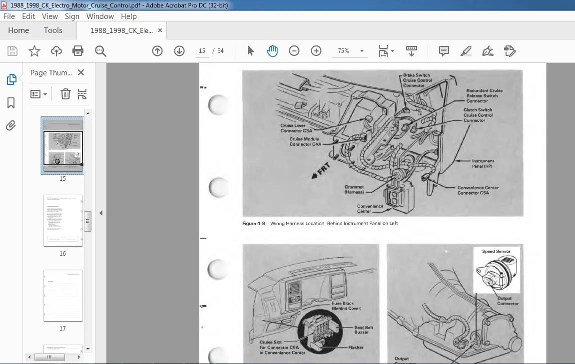
Wiring Harness Location: Behind Cable Installation (Step 6) ………………………………… . . 25
Instrument Panel on L e ft………………………………… .1 1
Cable Adjustment (Diesel L e v e r)………………………. . . 26
Convenience Center Location; Cable Adjustment (Step 4 ) ………………………………… 27
Behind Instrument Panel………………………………… . . 11
Cable Adjustment (Step 5 ) ………………………………… . . 27
PLEASE NOTE:
- This is the SAME manual used by the dealers to troubleshoot any faults in your vehicle. This can be yours in 2 minutes after the payment is made.
- Contact us at [email protected] should you have any queries before your purchase or that you need any other service / repair / parts operators manual.