Trusted Business
Verified & Licensed
Virus Free Files
100% Safe Downloads
Secure Payment
SSL Protected
Instant Delivery
Available Immediately
1998 NISSAN 240SX S14 Series Service Manual PDF DOWNLOAD
$35.95
1998 NISSAN 240SX S14 Series Service Manual PDF DOWNLOAD
Instant PDF Download
Available immediately
Save to Your Device
Download & keep forever
Antivirus Scanned
100% virus-free
Trusted Worldwide
175,000+ customers
Description
1998 NISSAN 240SX S14 Series Service Manual PDF DOWNLOAD
FILE DETAILS:
1998 NISSAN 240SX S14 Series Service Manual PDF DOWNLOAD
Language : English
Pages : 1496
Downloadable :Yes
File Type : PDF
IMAGES PREVIEW OF THE MANUAL:
TABLE OF CONTENTS:
1998 NISSAN 240SX S14 Series Service Manual PDF DOWNLOAD
fwd 1
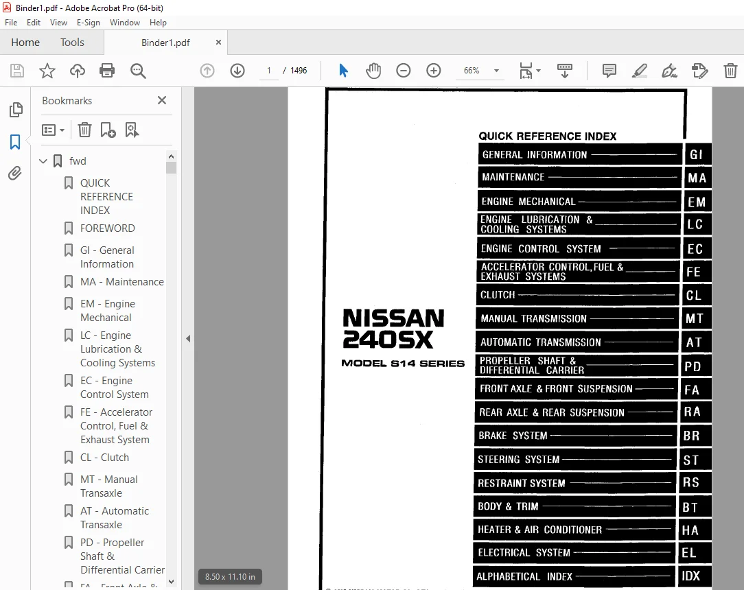
QUICK REFERENCE INDEX 1
FOREWORD 2
GI – General Information 0
MA – Maintenance 0
EM – Engine Mechanical 0
LC – Engine Lubrication & Cooling Systems 0
EC – Engine Control System 0
FE – Accelerator Control, Fuel & Exhaust System 0
CL – Clutch 0
MT – Manual Transaxle 0
AT – Automatic Transaxle 0
PD – Propeller Shaft & Differential Carrier 0
FA – Front Axle & Suspension 0
RA – Rear Axle & Suspension 0
BR – Brake System 0
ST – Steering System 0
RS – Restraint System 0
BT – Body & Trim 0
HA – Heater & Air Conditioner 0
EL – Electrical System 0
IDX – Alphabetical Index 1
Foldout 0
Comment Sheet 3
Quick Reference Chart 4
GST Mode 6 – Test Value & Test Limit Chart 5
at 6
QUICK REFERENCE INDEX 0
TABLE OF CONTENTS 6
DIAGNOSTIC TROUBLE CODE INDEX 8
Alphabetical & P No Index for DTC 8
PRECAUTIONS AND PREPARATION 9
Precautions for Supplemental Restraint System(SRS) “AIR BAG and “SEAT BELT PRE-TENSIONER” 9
Precautions for On Board Diagnostic (OBD) System of A/T and Engine 9
Precautions 10
Service Notice or Precautions 11
Special Service Tools 13
OVERALL SYSTEM 15
A/T Electrical Parts Location 15
Circuit Diagram 16
Wiring Diagram 17
Cross-sectional View 22
Hydraulic Control Circuits 23
Shift Mechanism 24
Control System 33
Control Mechanism 35
Control Valve 40
ON BOARD DIAGNOSTIC SYSTEM DESCRIPTION 42
Introduction 42
OBD-ll Function for A/T System 42
One or Two Trip Detection Logic of OBD-ll 42
OBD-ll Diagnostic Trouble Code (DTC) 42
Malfunction Indicator Lamp (MIL) 46
CONSULT 46
Diagnostic Procedure without CONSULT 52
TROUBLE DIAGNOSIS- Introduction 57
Introduction 57
Diagnostic Worksheet 57
Work Flow 61
TROUBLE DIAGNOSIS- Basic Inspection 62
A/T Fluid Check 62
Stall Test 62
Line Pressure Test 65
Road Test 67
TROUBLE DIAGNOSIS- General Description 77
Symptom Chart 77
TCM Terminals and Reference Value 80
DTC P0705, Inhibitor Switch 84
DTC P0710, A/T Fluid Temperature Sensor 88
DTC P0720, Vehicle Speed Sensor-A/T (Revolution sensor) 92
DTC P0725, Engine Speed Signal 95
DTC P0731, A/T 1ST Gear Function 98
DTC P0732, A/T 2ND Gear Function 103
DTC P0733, A/T 3RD Gear Function 107
DTC P0734, A/T 4TH Gear Function 111
DTC P0740, Torque Converter Clutch Solenoid Valve 119
DTC P0744, A/T TCC S/V Function (Lock-up) 123
DTC P0745, Line Pressure Solenoid Valve 130
DTC P0750, Shift Solenoid Valve A 134
DTC P0755, Shift Solenoid Valve B 138
DTC P1705, Throttle Position Sensor 142
DTC P1760, Overrun Clutch Solenoid Valve 148
TROUBLE DIAGNOSIS FOR BATT/FLUID TEMP SEN 152
A/T Fluid Temperature Sensor Cirsuit and TCM Power Source 152
TROUBLE DIAGNOSIS FOR VHCL SPEED SEN-MTR 156
Vehicle Speed Sensor-MTR 156
TROUBLE DIAGNOSIS FOR SYMPTOMS 159
1 O/D OFF Indicator Lamp Does Not Come On 159
2 Engine Cannot Be Started in “P” and “N” Position 160
3 In “P” Position, Vehicle Moves Forward Or Backward When Pushed 160
4 In “N” Position Vehicle Moves 161
5 Large Shock “N” – “R” Position 162
6 Vehicle Does Not Creep Backward In “R” Position 163
7 Vehicle Does Not Creep Forward In “D”, “2” Or “1” Position 164
8 Vehicle Cannot Be Started From D1 165
9 A/T Does Not Shift: D1 – D2 Or Does Not Kickdown: D4 -D2 166
10 A/T Does Not Shift : D2-D3 167
11 A/T Does Not Shift: D3-D4 168
12 A/T Does Not Perform Lock-up 169
13 A/T Does Not Hold Lock-up Condition 170
14 Lock-up Is Not Released 170
15 Engine Speed Does Not Return To Idle (light Braking D4-D3) 171
16 Vehicle Does Not Start From D, 172
17 A/T Does Not Shift: D4-D3, When Overdrive Control Switch “ON” – “OFF” 172
18 A/T Does Not Shift: D3 – 2-2, When Selector Lever “2” – “2” Position 173
19 A/T Does Not Shift: 2-2 – 1-1, When Selector Lever “2” – “1” Position 173
20 Vehicle Does Not Decelerate By Engine Brake 174
21 TCM Self-diagnosis Does Not Activate (inhibitor, Overdrive Control and Throttle Position Switch Circuit Checks) 174
TROUBLE DIAGNOSES – A/T Shift Lock System 180
Description 180
Wiring Diagram – SHIFT – 181
Diagnostic Procedure 182
Key Interlock Cable 184
Component Check 185
ON-VEHICLE SERVICE 187
Control Valve Assembly and Accumulators 187
Revolution Sensor Replacement 187
Rear Oil Seal Replacement 188
Parking Components Inspection 188
Inhibitor Switch Adjustment 189
Manual Control Linkeage Adjustment 189
REMOVAL AND INSTALLATION 190
Removal 190
Installation 192
MAJOR OVERHAUL 193
Oil Channel 195
Locations of Needle Bearings, Thust Washers and Snap Rings 196
DISASSEMBLY 197
Disassembly 197
REPAIR FOR COMPONENT PARTS 208
Oil Pump 208
Control Valve Assembly 212
Control Valve Upper Body 218
Control Valve Lower Body 223
Reverse Clutch 225
High Clutch 229
Forward and Overrun Clutches 231
Low & Reverse Brake 235
Forward Clutch Drum Assembly 239
Rear Internal Gear and Forward Clutch Hub 241
Band Servo Piston Assembly 244
Parking Pawl Components 248
ASSEMBLY 250
Assembly (1) 250
Adjustment 254
Assembly (2) 258
SERVICE DATA AND SPECIFICATIONS (SDS) 268
General Specifications 268
Specifications and Adjustment 268
br 272
QUICK REFERENCE INDEX 0
TABLE OF CONTENTS 272
PRECAUTIONS AND PREPARATION 274
Supplemental Restraint System (SRS) “AIR BAG” 274
Precautions for Brake System 274
Commercial Service Tools 274
NOISE, VIBRATION AND HARSHNESS (NVH) TROUBLESHOOTING 275
NVH Troubleshooting Chart 275
BRAKE HYDRAULIC LINE/CONTROL VALVE 276
Brake Hydraulic Line 276
Proportioning Valve 277
CHECK AND ADJUSTMENT 278
Checking Brake Fluid Level 278
Checking Brake Line 278
Changing Brake Fluid 278
Bleeding Brake System 279
BRAKE PEDAL AND BRACKET 280
Removal and Installation 280
Inspection 280
Adjustment 280
MASTER CYCLINDER 281
Removal 281
Disassembly 281
Inspection 281
Assembly 281
Installation 283
BRAKE BOOSTER/VACUUM HOSE 284
Brake Booster 284
Vacuum Hose 285
FRONT DISC BRAKE 286
Pad Replacement 286
Removal 288
Disassembly 288
Inspection – Caliper 288
Inspection – Rotor 289
Assembly 289
Installation 289
Brake Burnishing Procedure 290
REAR DISC BRAKE 291
Pad Replacement 286
Removal 293
Disassembly 293
Inspection – Caliper 294
Inspection – Rotor 295
Assembly 295
Installation 297
PARKING BRAKE CONTROL 298
Removal and Installation 298
Inspection 299
Adjustment 299
ANTI-LOCK BRAKE SYSTEM 300
Purpose 300
Operation 300
ABS Hydraulic Circuit 300
System Components 301
System Description 301
Removal and Installation 303
TROUBLE DIAGNOSIS 306
How to Perform Trouble Diagnosis for Quick and Accurate Repair 306
Preliminary Check 307
Component Parts and Harness Connector Location 308
Circuit Diagram for Quick Pinpoint Check 309
Wiring Diagram – ABS – 310
Self-diagnosis 315
CONSULT 318
CONSULT Inspection Procedure 319
Ground Circuit Check 324
TROUBLE DIAGNOSIS FOR SELF-DIAGNOSTIC ITEMS 325
Diagnostic Procedure 1 (Wheel sensor of rotor) 325
Diagnostic Procedure 2 (ABS actuator solenoid valve) 327
Diagnostic Procedure 3 (Solenoid valve relay) 328
Diagnostic Procedure 4 (Motor relay or motor) 331
Diagnostic Procedure 5 (Low Voltage) 334
Diagnostic Procedure 6 (Control unit) 335
TROUBLE DIAGNOSIS FOR SYMPTOMS 336
Diagnistic Procedure 7 (ABS works frequently ) 336
Diagnostic Procedure 8 (Unexpected pedal action) 337
Diagnostic Procedure 9 (Long stopping distance) 337
Diagnostic Procedure 10 (ABS does not work ) 338
Diagnostic Procedure 11 (Pedal vibration and noise) 338
Diagnostic Procedure 12 (Warning lamp does not come on when ignition switch is turned on ) 339
Diagnostic Procedure 13 (Warning lamp stays on when ignition switch is turned on ) 341
Electrical Component Inspection 344
SERVICE DATA AND SPECIFICATIONS (SDS) 346
General Specifications 346
Inspection and Adjustment 346
bt 347
QUICK REFERENCE INDEX 0
TABLE OF CONTENTS 347
PRECAUTIONS 348
Service Notice 348
Supplemental Restraint System (SRS) “AIR BAG” 348
GENERAL SERVICING 349
Clip and Fastener 349
BODY END 352
Body Front End 352
Body Rear End and Opener 355
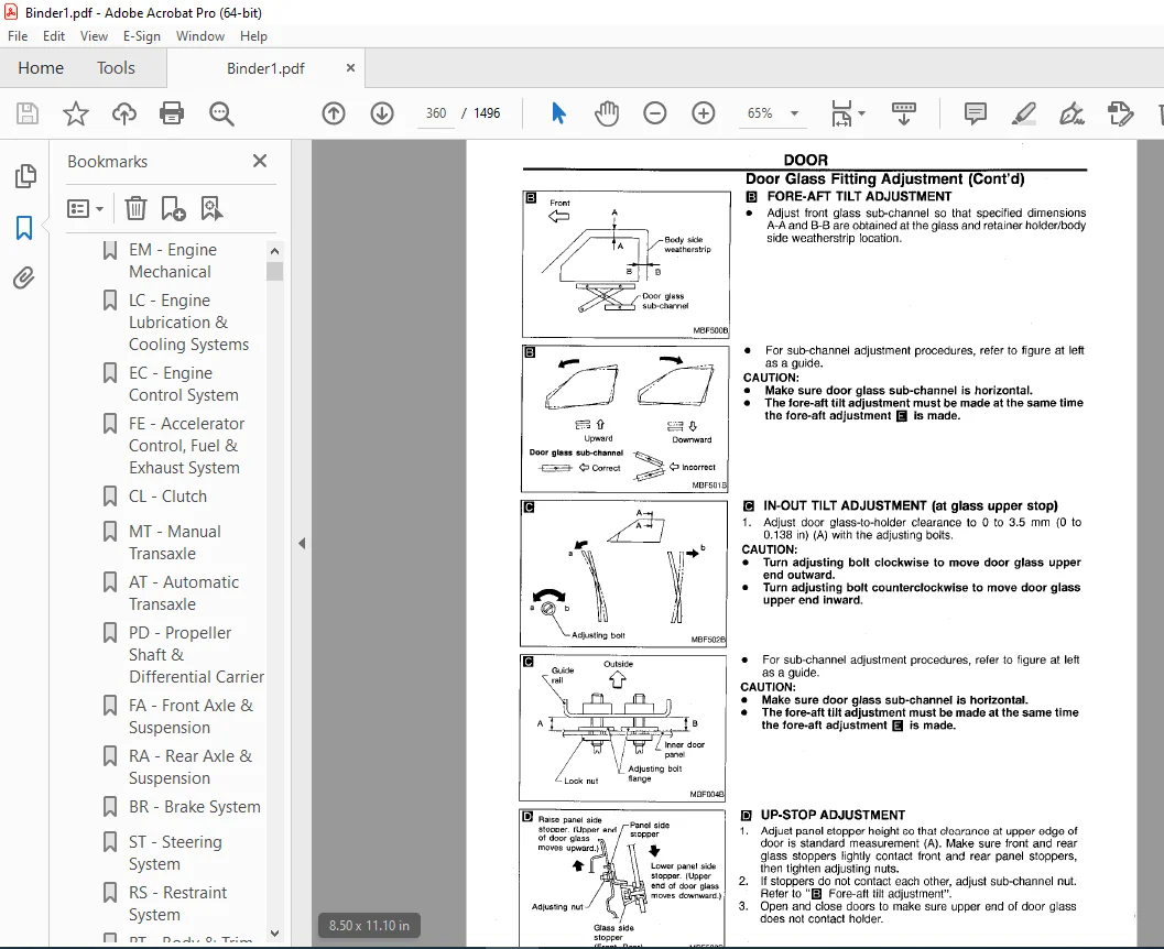
DOOR 357
Door Glass Fitting Adjustment 358
INSTRUMENT PANEL 362
INTERIOR TRIM 365
Side and Floor Trim 365
Door Trim 367
Roof Trim 368
Trunk Room Trim 369
EXTERIOR 370
SEAT 377
Front Seat 377
Rear Seat 379
SUNROOF 380
WINDSHIELD AND WINDOWS 384
Windshield and Rear Window 385
Side Window 386
MIRROR 387
Door Mirror 387
BODY ALIGNMENT 388
Engine Compartment 388
Underbody 390
cl 392
QUICK REFERENCE INDEX 0
TABLE OF CONTENTS 392
PRECAUTIONS AND PREPARATION 393
Precautions 393
Special Service Tools 393
Commercial Service Tools 393
NOISE VIBRATION AND HARSHNESS (NVH) TROUBLESHOOTING 394
NVH Troubleshooting Chart 394
CLUTCH SYSTEM 395
INSPECTION AND ADJUSTMENT 396
Adjusting Clutch Pedal 396
Air Bleeding Procedure 397
HYDRALULIC CLUTCH CONTROL 398
Clutch Master Cylinder 398
Operating Cylinder 399
CLUTCH RELEASE MECHANISM 400
CLUTCH DISC AND CLUTCH COVER 402
Clutch Disc 402
Clutch Cover and Flywheel 403
SERVICE DATA AND SPECIFICATIONS (SDS) 404
General Specifications 404
Inspection and Adjustment 404
ec 405
QUICK REFERENCE INDEX 0
TABLE OF CONTENTS 405
DIAGNOSTIC TROUBLE CODE INDEX 408
Alphabetical & P N0 Index for DTC 408
PRECAUTIONS AND PREPARATION 410
Special Service Tools 410
Commercial Service Tools 410
Supplemental Restraint System (SRS) “AIR BAG” 411
Precautions for On Board Diagnostic (OBD) 411
System of Engine and A/T 411
Engine Fuel & Emission Control System 412
Precautions 413
ENGINE AND EMISSION CONTROL OVERALL SYSTEM 415
Circuit Diagram 415
ECCS Component Parts Location 416
System Diagram 418
Vacuum Hose Drawing 419
System Chart 420
ENGINE AND EMISSION BASIC CONTROL SYSTEM DESCRIPTION 421
Multiport Fuel Injection (MFI) System 421
Distributor Ignition (D) System 423
Air Conditioning Cut Control 424
Fuel Cut Control (at no load & high engine speed) 425
EVAPORATIVE EMISSION SYSTEM 426
Description 426
Inspection 426
Evaporative Emission Line Drawing 429
POSITIVE CRANKCASE VENTILATION 431
Description 431
Inspection 431
BASIC SERVICE PROCEDURE 432
Fuel Pressure Release 432
Fuel Pressure Check 432
Fuel Pressure Regulator Check 433
Injector Removal and Installation 433
Idle Speed/Ignition Timing/Idle Mixture Ratio Adjustment 434
ON BOARD DIAGNOSTIC SYSTEM DESCRIPTION 440
Introduction 440
Two Trip Detection Logic 440
Emission-related Diagnostic Information 441
Malfunction Indicator Lamp (MIL) 452
OBD System Operation Chart 455
CONSULT 460
Generic Scan Tool (GST) 473
TROUBLE DIAGNOSIS-Introduction 475
Introduction 475
Diagnostic Worksheet 475
TROUBLE DIAGNOSIS- Work Flow 477
Work Flow 477
Description for Work Flow 478
TROUBLE DIAGNOSIS- Basic Inspection 479
Basic Inspection 479
TROUBLE DIAGNOSIS- General Description 482
Diagonstic Trouble Code (DTC) Inspection 482
Priority Chart 482
Fail Safe Chart 483
Symptom Matrix Chart 484
CONSULT Reference Graph in Data Monitor Mode 487
Major Sensor Reference Graph in Data Monitor Mode 490
ECM Terminals and Reference Value 492
TROUBLE DIAGNOSIS FOR INTERMITTENT INCIDENT 502
Description 502
Common l/l Report Situations 502
Diagnostic Procedure 502
TROUBLE DIAGNOSIS FOR POWER SUPPLY 503
Main Power Supply and Ground Circuit 503
DTC P0100, Mass Air Flow Sensor (MAFS) 508
DTC P0105, Absolute Pressure Sensor 517
DTC P0110, Intake Air Temperature Sensor 525
DTC P0115, Engine Coolant Temperature Sensor (ECTS) (Circuit) 531
DTC P0120, Throttle Position Sensor 536
DTC P0125, Engine Coolant Temperature (ECT) Sensor 547
DTC P0130, Front Heated Oxygen Sensor (Circuit) (Front HO2S) 552
DTC P0131, Front Heated Oxygen Sensor (Lean Shift Monitoring) (Front H02S) 558
DTC P0132, Front Heated Oxygen Sensor (Rich Shift Monitoring) (Front HO2S) 564
DTC P0133, Front Heated Oxygen Sensor (Response Monitoring ) (Front HO2S) 570
DTC P0134, Front Heated Oxygen Sensor (High Voltage) (Front HO2S) 578
DTC P0135, Front Heated Oxygen Sensor Heater 583
DTC P0137, Rear Heated Oxygen Sensor (Min Voltage Monitoring ) (Rear HO2S) 587
DTC P0138, Rear Heated Oxygen Sensor (Max Voltage Monitoring) (Rear H02S) 594
DTC P0139, Rear Heated Oxygen Sensor (Response Monitoring) (Rear HO2S) 601
DTC P0140, Rear Heated Oxygen Sensor (High Voltage) (Rear HO2S) 607
DTC P0141, Rear Heated Oxygen Sensor Heater 610
DTC P0171, Fuel Injection System Function (Lean side) 616
DTC P0172, Fuel Injection System Function (Rich side) 621
DTC P0180, Tank Fuel Temperature Sensor 626
DTC P0300 – P0304, No 4 – 1 Cylinder Misfire, Multiple Cylinder Misfire 630
DTC P0325, Knock Sensor (KS) 633
DTC P0335, Crankshaft Position Sensor (CKPS) (OBD) 638
DTC P0340, Camshaft Position Sensor (CMPS) 643
DTC P0400, EGR Function (Close) 649
DTC P0402, EGRC-BPT Valve Function 657
DTC P0420, Three Way Catalyst Function 662
DTC P0440, Evaporative Emssion (EVAP) Control System (Small Leak) (Negative Pressure) 666
DTC P0443, Evaporative Emssion (EVAP) Canister Purge Volume Control Valve (Circuit) 677
DTC P0446, Evaporative Emssion (EVAP) Canister Vent Control Valve (Curcuit) 683
DTC P0450, Evaporative Emssion (EVAP) Control System Pressure Sensor 688
DTC P0500, Vehicle Speed Sensor (VSS) 693
DTC P0505, Idle Air Control Valve (IACV) – Auxiliary Air Control (ACC) Valve 697
DTC P0510, Closed Trrottle Position Switch 704
DTC P0600, A/T Control 709
DTC P0605, Engine control Module (ECM)-ECCS Control Module 712
DTC P1105, Mainfold Absolute Pressure (MAP)/Barometric Pressure (BARO) Switch Solenoid Valve 714
DTC P1148, Close Loop Control 722
DTC P1320, Ignition Signal 724
DTC P1336, Crankshaft Position Sensor (CKPS) (OBD) (COG) 730
DTC P1400, EGRC-Solenoid Valve 735
DTC P1401, EGR Temperature Sensor 740
DTC P1402, EGR Function (Open) 746
DTC P1440, Evaporative Emssion (EVAP) Control System (Small Leak) (Positive Pressure) 753
DTC P1444, Evaporative Emssion (EVAP) Canister Purge Volume Control Valve 764
DTC P1446, Evaporative Emssion (EVAP) Canister Vent Control Valve (Close) 771
DTC P1447, Evaporative Emssion (EVAP) Control system Purge Flow Monitoring 776
DTC P1448, Evaporative Emssion (EVAP) Canister Vent Control Valve (Open) 784
DTC P1490, Vacuum Cut Valve Bypass Valve 789
DTC P1491, Vacuum Cut Valve Bypass Valve 794
DTC P1492, Evaporative Emssion (EVAP) Canister Purge Control Valve/Solenoid Valve (Circuit) 799
DTC P1493, Evaporative Emssion (EVAP) Canister Purge Control Valve/Solenoid Valve 804
DTC P1605, A/T Diagnosis Communication Line 811
DTC P1706, Park/Netural Position Switch 814
TROUBLE DIAGNOSIS FOR OVERHEAT 819
Overheat 819
TROUBLE DIAGNOSIS FOR NON-DETECTABLE ITEMS 831
Injector 831
Start Signal 834
Fuel Pump 837
Power Steering Oil Pressure Switch 842
IACV-Air Regulator 846
IACV-FICD Solenoid Valve 849
5th Position Switch 854
Electric Load signal 856
MIL & Data Link Connectors 858
SERVICE DATA AND SPECIFICATIONS (SDS) 859
General Specifications 859
Inspection and Adjustment 859
el 861
QUICK REFERENCE INDEX 0
TABLE OF CONTENTS 861
PRECAUTIONS 864
Supplemental Restraint System (SRS) “AIR BAG” 864
HARNESS CONNECTOR 865
Description 865
STANDARDIZED RELAY 866
Description 866
POWER SUPPLY ROUTING 868
Schematic 868
Wiring Diagram – POWER- 869
Fuse 874
Fusible Link 874
Circuit Breaker Inspection 874
GROUND DISTRIBUTION 875
BATTERY 878
How to Handle Battery 878
Service Data and Specifications (SDS) 881
STARTING SYSTEM 882
System Description 882
Wiring Diagram – START – /M/T MODELS 884
Wiring Diagram – START – /A/T MODELS 885
Construction 886
Removal and Installation 886
Pinion/Clutch Check 887
Service Data and Specifications (SDS) 887
CHARGING SYSTEM 888
System Description 888
Wiring Diagram – CHARGE – 889
Construction 890
Removal and Installation 890
Trouble Diagnoses 891
Service Data and Specifications (SDS) 892
COMBINATION SWITCH 893
Check 893
Replacement 894
STEERING SWITCH 895
Check 895
HEADLAMP 896
System Description (For USA) 896
Wiring Diagram – H/LAMP- 897
Trouble Diagnosis 898
Bulb Replacement 899
Aiming Adjustment 900
HEADLAMP – Daytime Light System – 901
System Description (For Canada) 901
Operation 902
Schematic 903
Wiring Diagram -DTRL- 904
Trouble Diagnoses 907
Bulb Replacement 908
Aiming Adjutment 908
PARKING LICENSE, TAIL AND STOP LAMPS 909
Wiring Diagram – TAIL/L – 909
BACK-UP LAMP 911
Wiring Diagram – BACK/L – 911
FRONT FOG LAMP 913
System Description 913
Wiring Diagram – F/FOG – 914
Aiming Adjustment 915
TURN SIGNAL AND HAZARD WARNING LAMPS 916
System Description 916
Wiring Diagram- TURN – 919
Trouble Diagnoses 922
Electrical Components Inspection 922
ILLUMINATION 923
System Description 923
Schematic 924
Wiring Diagram – INT/L – 925
INTERIOR SPOT AND TRUNK ROOM LAMPS 928
System Description 928
Wiring Diagram – INT/L 929
METER AND GAUGES 931
System Description 931
Combination Meter 932
Wiring Diagram – METER – 933
Trouble Diagnoses 934
Electrical Components Inspection 937
WARNING LAMPS 938
Schematic 938
Wiring Diagram – WARN- 937
Electrical Components Inspection 942
WARNING BUZZER 943
System Description 943
Wiring Diagram – BUZZER- /Models With 945
Power Door Locks 945
Wiring Diagram – BUZZER-/Models Without 946
Power Door Locks 946
Trouble Diagnoses 947
Electrical Components Inspection 951
WIPER AND WASHER 952
System Description 952
Wiring Diagram – WIPER-/Without Intermittent Wiper 954
Wiring Diagram-WIPER-/With Intermittent Wiper 955
Trouble Diagnoses/With Intermittent Wiper 957
Removal and Installation 959
Washer Nozzle Adjustment 960
Washer Tube Layout 961
HORN 962
Wiring Diagram – HORN – 962
CIGARETTE LIGHTER 963
Wiring Diagram – CIGAR – 963
CLOCK 964
Wiring Diagram – CLOCK 964
REAR WINDOW DEFOGGER 965
System Description 965
Wiring Diagram – DEF – 966
Trouble Diagnoses 968
Electrical Components Inspection 970
Filament Check 970
Filament Repair 971
AUDIO 973
System Description 973
Wiring Diagram – AUDIO – /4-speaker 974
Wiring Diagram – AUDIO – /6-speaker 975
Trouble Diagnoses 977
AUDIO ANTENNA 978
System Description 978
Wiring Diagram – P/ANT – 979
Trouble Diagnoses 980
Location of Atenna 980
Antenna Rod Replacement 980
Window Antenna Repair 981
POWER SUNROOF 983
Wiring Diagram – SROOF- 983
POWER DOOR MIRROR 984
Wiring Diagram – MIRROR – 984
AUTOMATIC SPEED CONTROL DEVICE (ASCD) 986
Component Parts and Harness Connector Location 986
System Description 987
Schematic 989
Wiring Diagram – ASCD – 990
CONSULT 995
Fail-safe System Description 997
Fail-safe System Check 998
Trouble Diagnoses 999
Electrical Components Inspection 1007
ASCD Wire Adjustment 1008
POWER WINDOW 1009
System Description 1009
Wiring Diagram – Window – 1011
Trouble Diagnoses 1013
POWER DOOR LOCK 1014
System Description 1014
Wiring Diagram – D/LOCK 1015
Trouble Diagnoses 1017
MULTI-REMOTE CONTROL SYSTEM 1020
System Description 1020
Schematic 1020
Wiring Diagram – MULTI 1023
Trouble Diagnoses 1026
Electrical Components Inspection 1032
ID Code Entry Procedure 1033
THEFT WARNING SYSTEM 1034
Component Parts and Harness Connector 1034
Location 1034
System Description 1035
Schematic 1038
Wiring Diagram – THEFT – 1039
Trouble Diagnoses 1044
SMART ENTRANCE CONTROL UNIT 1058
Description 1058
Smart Entrance Control Unit Inspection Table 1059
Schematic 1060
LOCATION OF ELECTRICAL UNITS 1062
Engine Compartment 1062
Passenger Compartment 1063
HARNESS LAYOUT 1065
Outline 1065
Main Harness 1066
Engine Room Harness 1068
Engine Harness 1071
Engine Control Harness 1072
Body Harness and Tail Harness 1074
Room Lamp Harness 1076
Air Bag Harness 1077
Door Harness LH 1080
Door Harness RH 1080
BULB SPECIFICATIONS 1079
Headlamp 1079
Exterior Lamp 1079
Interior Lamp 1079
WIRING DIAGRAM CODES (CELL codes) 1080
SUPER MULTIPLE JUNCTION (SMJ) 0
Disconnectiong and Connecting 0
Terminal Arrangement 1
ELECTRICAL UNITS 2
Terminal Arrangement 2
em 1081
QUICK REFERENCE INDEX 0
TABLE OF CONTENTS 1081
PRECAUTIONS 1082
Parts Requiring Angular Tightening 1082
Liquid Gasket Application Procedure 1082
PREPARATION 1083
Special Service Tools 1083
Commercial Service Tools 1086
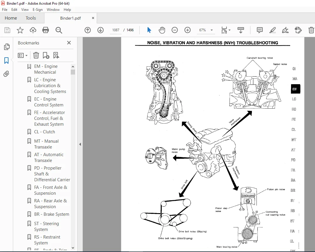
NOISE, VIBRATION AND HARSHNESS (NVH) TROUBLESHOOTING 1087
NVH Troubleshooting Chart-Engine Noise 1088
OUTER COMPONENT PARTS 1089
COMPRESSION PRESSURE 1091
Measurement of Compression Pressure 1091
OIL PAN 1092
Removal 1092
Installation 1093
TIMING CHAIN 1094
Removal 1096
Inspection 1099
Installation 1099
OIL SEAL REPLACEMENT 1103
CYLINDER HEAD 1105
Removal and Installation 1106
Disassembly 1106
Inspection 1107
Assembly 1112
Valve Clearance 1112
ENGINE REMOVAL 1115
Removal 1116
CYLINDER BLOCK 1117
Disassembly 1118
Inspection 1119
Assembly 1125
SERVICE DATA AND SPECIFICATION (SDS) 1128
General Specifications 1128
Inspection and Adjustment 1128
fa 1136
QUICK REFERENCE INDEX 0
TABLE OF CONTENTS 1136
PRECAUTIONS AND PREPARATION 1137
Precautions 1137
Special Service Tools 1137
Commercial Service Tools 1138
NOISE, VIBRATION AND HARSHNESS (NVH) TROUBLESHOOTING 1139
NVH Troubleshooting Chart 1139
FRONT SUSPENSION SYSTEM ON-VEHICLE SERVICE 1140
ON-VEHICLE SERVICE 1141
Front Axle and Front Suspension Parts 1141
Front Wheel Bearing 1141
Front Wheel Alignment 1142
FRONT AXLE 1144
Wheel Hub and Knuckle 1144
ABS Sensor Rotor 1146
Battle Plate 1147
FRONT SUSPENSION 1148
Coil Spring and Strut Assembly 1149
Tension Rod and Stabilizer Bar 1150
Transverse Link and Lower Ball Joint 1151
SERVICE DATA AND SPECIFICATIONS (SDS) 1152
General Specifications 1152
Inspection and Adjustment 1153
fe 1154
QUICK REFERENCE INDEX 0
TABLE OF CONTENTS 1154
PREPARATION/ACCELERATOR CONTROL SYSTEM 1155
Special Service Tool 1155
Accelerator Control System 1155
Adjusting Accelerator Wire 1155
FUEL SYSTEM 1156
Fuel Tank 1156
Fuel Pump and Gauge 1158
EXHAUST SYSTEM 1160
foldout 1161
QUICK REFERENCE INDEX 0
ELECTRICAL SYSTEM 2
SUPER MULTIPLE JUNCTION (SMJ) 1161
Disconnecting and Connecting 1161
Terminal Arrangement 1162
ELECTRICAL UNITS 1163
Terminal Arrangement 1163
gi 1164
QUICK REFERENCE INDEX 0
TABLE OF CONTENTS 1164
PRECAUTIONS 1165
Precautions for Supplemental Restraint System (SRS) “AIR BAG” 1165
General Precautions 1165
Precautions for Multiport Fuel Injection System or EC CS ENGINE 1167
Precautions for Three Way Catalyst 1168
Precautions for Engine Oils 1168
Precautions for Fuel 1169
Precautions for Air Conditioning 1169
HOW TO USE THIS MANUAL 1170
HOW TO READ WIRING DIAGRAMS 1172
Sample/Wiring EDiagram-EXAMPLE-Description 1172
HOW TO CHECK TERMINAL 1181
Connector and Terminal Pin Kit 1181
How to Probe Connectors 1181
How to Check Entarged Contact Spring of Terminal 1182
Waterproof Connector Inspection 1183
Terminal Lock Inspection 1183
HOW TO PERFORM EFFCIENT DIAGNOSIS FOR AN ELECTRICAL INCIDENT 1184
Work Flow 1184
Incident Simulation Tests 1185
Circuit Inspection 1188
HOW TO FOLLOW FLOW CHART IN TROUBLE DIAGNOSES 1194
CONSULT CHECKING SYSTEM 1197
Function and System Application 1197
Lithium Battery Replacement 1197
Checking Equipment 1197
Loading Procedure 1198
Consult Data Link Connector (DLC) Circuit 1198
IDENTIFICATION INFORMATION 1199
Model Variation 1199
Identification Number 1200
Dimensions 1202
Wheels and Tires 1202
LIFTING POINTS AND TOW TRUCK TOWING 1203
Preparation 1203
Board-on Lift 1203
Garage Jack and Safety Stand 1204
2-pole Lift 1205
Tow Truck Towing 1205
TIGHTENING TORQUE OF STANDARD BOSTS SAE J1930 TERMINOLOGY LIST 1207
SAE J1930 Terminology List 1208
ha 1212
QUICK REFERENCE INDEX 0
TABLE OF CONTENTS 1212
PRECAUTIONS AND PREPARATION 1213
Supplemental Restraint System (SRS) “AIR BAG” 1213
Precautions for Working with HFC-134a (R-134a) 1213
General Refrigerant Precautions 1213
Precautions for Refrigerant Connection 1214
Precautions for Servicing Compressor 1217
Special Service Tools 1217
HFC-134A (R-134a) Service Tools and Equipment 1218
Precautions for Service Equipment 1220
DESCRIPTION 1222
Refrigeration Cycle 1222
V-6 Variable Displacement Compressor 1223
Component Layout 1229
Discharge Air Flow 1230
Control Operation 1231
TROUBLE DIAGNOSIS 1232
How to Perform Trouble Diagnosis for Quick an Accurate Repair 1232
Operational Check 1233
Symptom Chart 1235
Preliminary Check 1237
Performance Test Diagnoses 1243
Performance Chart 1245
Trouble Diagnosis for Abnormal Pressure 1246
Harness Layout 1249
Circuit Diagram 1251
Wiring Diagram-A/C- 1252
Main Power Supply and Ground Circuit Check 1258
Diagnostic Procedure 1 1259
Diagnostic Procedure 2 1261
Diagnostic Procedure 3 1263
Diagnostic Procedure 4 1264
Diagnostic Procedure 5 1266
Diagnostic Procedure 6 1267
Electrical Components Inspection 1270
Control Linkage Adjustments 1272
SERVICE PROCEDURES 1274
HFC-134a (R-134a) Service Procedure 1274
Maintenance of Lubricant Quantity in Compressor 1276
Refrigerant Lines 1278
Compressor Mounting 1281
Belt Tension 1281
Past Idle Control Device (FICD) 1281
Compressor 1282
Compressor Clutch 1282
Push Control Unit 1286
SERVICE DATA AND SPECIFICATIONS 1287
General Speciifications 1287
Inspection and Adjustment 1287
idx 1288
QUICK REFERENCE INDEX 0
lc 1296
QUICK REFERENCE INDEX 0
TABLE OF CONTENTS 1296
PRECAUTION AND PREPARATION 1297
Liquid Gasket Application Procedure 1297
Special Service Tools 1297
ENGINE LUBRICATION SYSTEM 1299
Lubrication Circuit 1299
Oil Pressure Check 1299
Oil Pump 1300
ENGINE COOLING SYSTEM 1302
Cooling Circuit 1302
System Check 1302
Water Pump 1303
Thermostat 1304
Radiator 1305
Cooling Fan (Crankshaft driven) 1308
Cooling Fan Control System 1309
Overheating Cause Analysis 1310
SERVICE DATA AND SPECIFICATIONS (SDS) 1311
Engine Lubrication System 1311
Engine Cooling System 1311
ma 1312
QUICK REFERENCE INDEX 0
TABLE OF CONTENTS 1312
PRECAUTIONS AND PREPARATION 1313
Supplemental Restraint System (SRS) “AIR BAG” 1313
Special Service Tool 1313
GENERAL MAINTENANCE 1314
PERIODIC MAINTENANCE 1316
Schedule 1 1317
Schedule 2 1318
RECOMMENDED FLUIDS AND LUBRICANTS 1319
Fluids and Lubricants 1319
SAE Viscosity Number 1319
Anti-freeze Coolant Mixture Ratio 1320
ENGINE MAINTENANCE 1321
Checking Drive Belts 1321
Changing Engine Coolant 1322
Checking Fuel Lines 1323
Changing Fuel Filter 1324
Changing Air Cleaner Filter 1324
Changing Engine Oil 1325
Changing Oil Filter 1325
Changing Spark Plugs 1326
Checking EVAP Vapor Lines 1327
CHASSIS AND BODY MAINTENANCE 1328
Checking Exhaust 1328
Checking Clutch Fluid Level and Leaks 1328
Checking M/T Oil 1328
Checking M/T Oil 1328
Checking A/T FLUID 1329
Checking A/T FLUID 1329
Checking Differential Gear Oil 1330
Checking Differential Gear Oil 1330
Balancing Wheels 1330
Tire Rotation 1330
Checking Brake Fluid Level and Leaks 1330
Checking Brake Lines and Cables 1331
Checking Steering Gear and Linkage 1331
Checking Power Steering Fluid and lines 1332
Lubricationg Locks, Hinges and Hood Latches 1333
Checking Seat Belts, Buckles, Retractors, Anchors and Adjusters 1333
SERVICE DATA AND SPECIFICATIONS (SDS) 1334
Engine Maintenance 1334
Chassis and Body Maintenanace 1334
mt 1335
QUICK REFERENCE INDEX 0
TABLE OF CONTENTS 1335
PREPARATION 1336
Special Service Tools 1336
Commercial Service Tool 1338
NOISE, VIBRATION AND HARSHNESS (NVH) TROUBLESHOOTING 1339
NVH Troubleshooting Chart 1339
DESCRIPTION 1340
Cross-sectional View 1340
ON-VEHICLE SERVICE 1341
Replacing Rear Oil Seal 1341
Position Switch Check 1341
REMOVAL AND INSTALLATION 1342
Removal 1342
Installation 1343
MAJOR OVERHAUL 1344
Case components 1344
Gear Components 1345
Shift Control Components 1346
DISASSEMBLY 1347
Case Components 1347
Shift Control Components 1348
Gear Components 1348
ASSEMBLY 1353
Gear Components 1353
Shift Control Components 1359
Case Components 1360
SERVICE DATA AND SPECIFICATIONS (SDS) 1363
General Specifications 1363
Inspection and Adjustment 1363
pd 1365
QUICK REFERENCE INDEX 0
TABLE OF CONTENTS 1365
PREPARATION 1366
Special Service Tools 1366
Commercial Service Tools 1368
NOISE, VIBRATION AND HARSHNESS (NVH) TROUBLESHOOTING 1369
NVH Troubleshooting chart 1369
PROPELLER SHAFT 1370
On-vehicle Service 1371
Removal 1371
Installation 1371
Inspection 1372
Disassembly 1373
Assembly 1373
FINAL DRIVE 1374
ON-VEHICLE SERVICE/REMOVAL AND INSTALLATION 1374
Front Oil Seal Replacement 1374
Side Oil Seal Replacement 1374
Removal 1375
Installation 1376
FINAL DRIVE 1377
DISASSEMBLY 1379
Pre-inspection 1379
Differential Carrier 1379
Differential Case 1381
INSPECTION 1383
Ring Gear and Drive Pinion 1383
Bearing 1383
Differential Case Assembly 1383
ADJUSTMENT 1384
Side Bearing Preload 1384
Pinion Gear Height and Pinion Bearing Preload 1385
Tooth Contact 1390
ASSEMBLY 1391
Differential Case 1391
Differential Carrier 1393
SERVICE DATA AND SPECIFICATIONS (SDS) 1397
Propeller Shaft 1397
Final Drive 1397
ra 1399
QUICK REFERENCE 0
TABLE OF CONTENTS 1399
PRECAUTIONS AND PREPARATION 1400
Precautions 1400
Special Service Tools 1400
Commercial Service Tools 1401
NOISE, VIBRATION AND HARSHNESS (NVH) TROUBLESHOOTING 1402
NVH Troubleshooting Chart 1402
REAR SUSPENSION SYSTEM ON-VEHICLE SERVICE 1403
Rear Axle and Rear Suspension Parts 1404
Rear Wheel Bearing 1404
Rear Wheel Alignment 1404
Drive Shaft 1406
REAR AXLE 1407
Wheel Hub and Axle Housing 1407
Drive Shaft 1411
REAR SUSPENSION 1417
Removal and Installation 1418
Coil Spring and Shock Abscrber 1419
Multi-link and Lower Ball Joint 1420
Stabilizer Bar 1421
SERVICE DATA AND SPECIFICATIONS (SDS) 1422
General Specifications 1422
Inspection and Adjustment 1423
rs 1424
QUICK REFERENCE INDEX 0
TABLE OF CONTENTS 1424
PRECAUTIONS 1425
Supplemental Restraint System (SRS) “AIR BAG” 1425
SEAT BELTS 1426
Front Seat Belt 1426
Rear Seat Belt 1427
Seat Belt Inspection 1428
SUPPLEMENTAL RESTRAINT SYSTEM (SRS) 1431
Precautions for SRS “AIR BAG” Service 1431
Special Service Tools 1431
Description 1432
SRS Component Parts Location 1432
Maintenance Items 1433
Removal and Installation – Diagnosis Sensor Unit 1434
Removal- Air Bag Module and Spiral Cable 1435
Removal- Front Passenger Air Bag Module 1436
Installation-Air Bag Module and Spiral Cable 1437
Installation-Front Passenger Air Bag Module 1438
Disposal of Air Bag Module 1439
TROUBLE DIAGNOSIS – Supplemental Restraint System (SRS) 1443
Trouble Diagnosis Introduction 1443
How to Perform Trouble Diagnoisis for Quick and Accurate Repair 1445
Schematic 1447
Wiring Diagram- SRS- 1448
Self-diagnosis 1450
Trouble Diagnosis for Air Bag Warning Lamp 1464
COLLISION DIAGNOSIS 1466
st 1468
QUICK REFERENCE INDEX 0
TABLE OF CONTENTS 1468
PRECAUTIONS AND PREPARATION 1469
Supplemental Restraint System (SRS) “AIR BAG” 1469
Precautions for Steering 1469
Special Service Tools 1469
Commercial Service Tools 1471
NOISE, VIBRATION AND HARSHNESS (NVH) TROUBLESHOOTING 1472
NVH Troubleshooting Chart 1472
ON-VEHICLE SERVICE 1473
Checking Steering Wheel Play 1473
Checking Neutral Position on Steering Wheel 1473
Front Wheel Turning Angle 1473
Checking Gear Housing Movement 1474
Adjusting Rack Retainer 1474
Checking and Adjusting Drive Belts 1474
Checking Fluid Level 1474
Checking Fluid Leakage 1474
Bleeding Hydraulic System 1475
Checking Steering Wheel Turning Force 1475
Checking Hydraulic System 1476
STEERING WHEEL AND STEERING COLUMN 1478
Removal and Installation 1478
Disassembly and Assembly 1480
Inspection 1481
POWER STEERING GEAR AND LINKAGE (MODEL PR24AC 1482
Removal and Installation 1482
Disassembly and Assembly 1484
Disassembly 1485
Inspection 1485
Assembly 1486
Adjustment 1490
POWER STEERING OIL PUMP 1492
Disassembly and Assembly 1492
Pre-disassembly Inspection 1492
Disassembly 1493
Inspection 1493
Assembly 1494
SERVICE DATA AND SPECIFICATIONS (SDS) 1495
General Specifications 1495
Inspection and Adjustment 1495
Questions? Email us: [email protected]
https://vimeo.com/849411162?share=copy
DESCRIPTION:
1998 NISSAN 240SX S14 Series Service Manual PDF DOWNLOAD
FOREWORD
- This manual contains maintenance and repair procedures for the 1998 Nissan 240SX. In order to assure your safety and the efficient functioning of the vehicle, this manual should be read thoroughly.
- It is especially important that the PRECAUTIONS in the GI section be completely understood before starting any repair task.
- All information in this manual is based on the latest product information at the lime of publication. The right is reserved to make changes in specifications and methods al any time without notice.
PRECAUTIONS:
• Before proceeding with disassembly, thoroughly clean the outside of the transaxle. It is important to prevent the internal parts from becoming contaminated by dirt or other foreign matter.
• Disassembly should be done in a clean work area.
• Use lint-free cloth or towels for wiping parts clean. Common shop rags can leave fibers that could interfere with the operation of the transaxle.
• Place disassembled parts in order for easier and proper assembly.
• All parts should be carefully cleaned with a general purpose, non-flammable solvent before inspection or reassembly. • Gaskets, seals and O-rings should be replaced any time the transaxle is disassembled.
• It is very important to perform functional tests whenever they are indicated.
• The valve body contains precision parts and requires extreme care when parts are removed and serviced. Place disassembled valve body parts in order for easier and proper assembly. Care will also prevent springs and small parts from becoming scattered or lost.
• Properly installed valves, sleeves, plugs, etc. will slide along bores in valve body under their own weight.
• Before assembly, apply a coat of recommended ATF to all parts. Apply petroleum jelly to protect O-rings and seals, or hold bearings and washers in place during assembly. Do not use grease.
• Extreme care should be taken to avoid damage to O-rings, seals and gaskets when assembling.
• Replace ATF cooler if excessive foreign material is found in oil pan or clogging strainer. Refer to “ATF COOLER SERVICE” (Refer to AT-6).
• After overhaul, refill the transmission with new ATF.
• When the Arr drain plug is removed, only some of the fluid is drained. Old Arr fluid will remain in torque converter and ATF cooling system. Always follow the procedures under “Changing Arr Fluid” in the MA section when changing Arr fluid.
PLEASE NOTE:
- This is the same manual used by the dealers to diagnose and troubleshoot your vehicle
- You will be directed to the download page as soon as the purchase is completed. The whole payment and downloading process will take anywhere between 2-5 minutes
- Need any other service / repair / parts manual, please feel free to contact [email protected] . We still have 50,000 manuals unlisted
G.P