Trusted Business
Verified & Licensed
Virus Free Files
100% Safe Downloads
Secure Payment
SSL Protected
Instant Delivery
Available Immediately
1998 NISSAN MAXIMA A32 Series Service Manual PDF DOWNLOAD
$24.95
1998 NISSAN MAXIMA A32 Series Service Manual PDF DOWNLOAD
Instant PDF Download
Available immediately
Save to Your Device
Download & keep forever
Antivirus Scanned
100% virus-free
Trusted Worldwide
175,000+ customers
Description
1998 NISSAN MAXIMA A32 Series Service Manual PDF DOWNLOAD
FILE DETAILS:
1998 NISSAN MAXIMA A32 Series Service Manual PDF DOWNLOAD
Language : English
Pages : 1695
Downloadable :Yes
File Type : PDF
IMAGES PREVIEW OF THE MANUAL:
Contact us: [email protected]
https://vimeo.com/852068870?share=copy
TABLE OF CONTENTS:
1998 NISSAN MAXIMA A32 Series Service Manual PDF DOWNLOAD
fwd 1
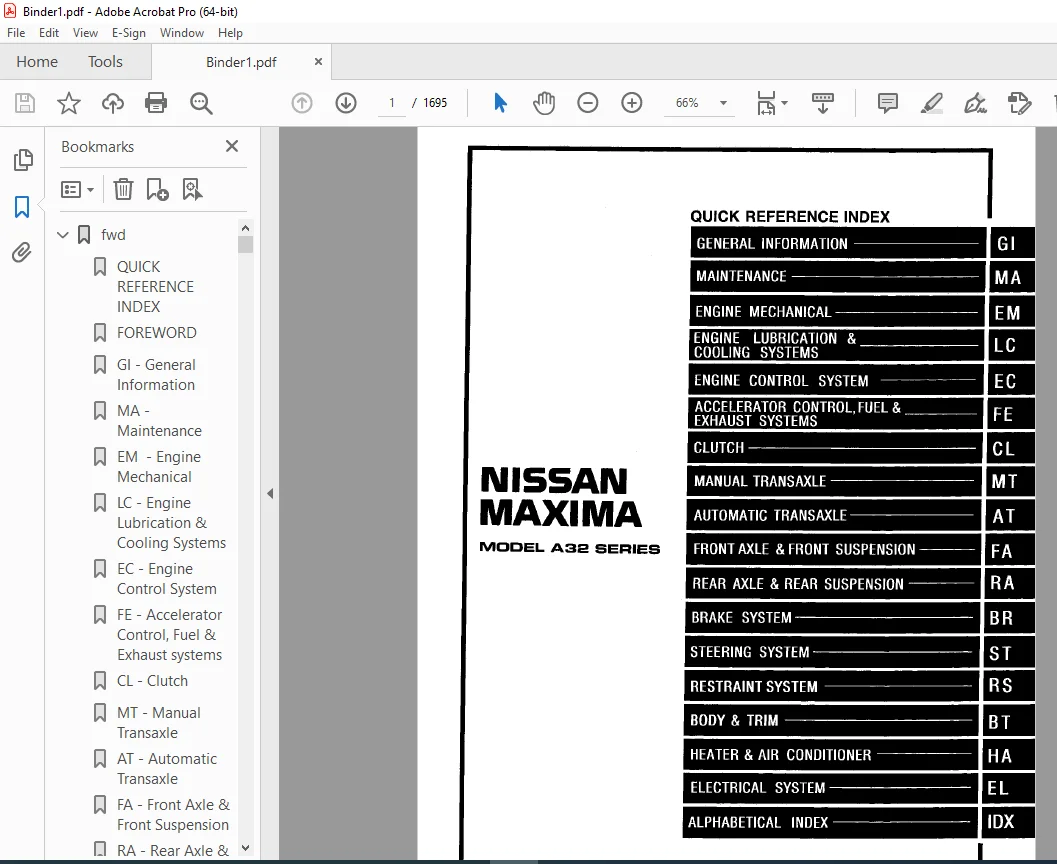
QUICK REFERENCE INDEX 1
FOREWORD 2
GI – General Information 0
MA – Maintenance 0
EM – Engine Mechanical 0
LC – Engine Lubrication & Cooling Systems 0
EC – Engine Control System 0
FE – Accelerator Control, Fuel & Exhaust systems 0
CL – Clutch 0
MT – Manual Transaxle 0
AT – Automatic Transaxle 0
FA – Front Axle & Front Suspension 0
RA – Rear Axle & Rear Suspension 0
BR – Brake System 0
ST – Steering System 0
RS Restraint System 0
BT – Body & Trim 0
HA – Heater & Air Conditioner 0
EL – Electrical System 0
IDX – Alphabetical Index 1
Foldout 0
Comment Sheet 3
Quick Reference Chart 4
GST Mode 6 – Test Value & Test Limit Chart 5
AT 6
QUICK REFERENCE INDEX 0
TABLE OF CONTENTS 6
DIAGNOSTIC TROUBLE CODE INDEX 8
Alphatbetical & P No Index for DTC 8
PRECAUTIONS AND PREPARATION 9
Supplemental Restraint System (SRS) “AIR BAG” 9
Precautions for On Board Diagnostic (OBD) System of A/T and Engine 9
Precautions 10
Service Notice or Precautions 11
Special Service Tools 13
Commercial Service Tools 16
OVERALL SYSTEM 17
A/T Electrical Parts Location 17
Circuit Diagram for Quick Pinpoint Check 18
Wiring Diagram – AT – 19
Cross-sectional View 26
Hydraulic Control Circuit 27
Shift Mechanism 28
Control System 37
Control Mechanism 39
Control Valve 44
ON BOARD DIAGNOSTIC SYSTEM DESCRIPTION 45
Introduction 45
OBD-II Function for A/T System 45
One or Two Trip Detection Logic of OBD-II 45
OBD-II Diagnostic Trouble Code (DTC) 45
Malfunction Indicator Lamp (MIL) 49
CONSULT 49
Diagnostic Procedure without CONSULT 56
TROUBLE DIAGNOSIS – Introduction 60
Introduction 60
Diagnostic Worksheet 61
Work Flow 64
TROUBLE DIAGNOSIS – Basic Inspection 65
A/T Fluid Check 65
Stall Test 65
Line Pressure Test 68
Road Test 69
TROUBLE DIAGNOSIS – General Description 80
Symptom Chart 80
TCM Terminals and Reference Value 83
TROUBLE DIAGNOSIS FOR POWER SUPPLY 87
Main Power Supply and Ground Circuit 87
DTC P0705, Inhibitor Switch 88
DTC P0710, A/T Fluid Temperature Sensor 92
DTC P0720, Vehicle Speed Sensor-A/T (REVOLUTION SENSOR) 96
DTC P0725, Engine Speed Signal 99
DTC P0731, A/T 1st Gear Function 102
DTC P0732, A/T 2nd Gear Function 107
DTC P0733, A/T 3rd Gear Function 112
DTC P0734, A/T 4th Gear Function 117
DTC P0740, Torque converter Clutch Solenoid Valve 125
DTC P0744, A/T TCC S/V Function (Lock-up) 129
DTC P0745, Line Pressure Solenoid Valve 136
DTC P0750, Shift Solenoid Valve A 140
DTC P0755, Shift Solenoid Valve B 144
DTC P1705, Throttle Position Sensor 148
DTC P1760, Overrun Clutch Solenoid Valve 154
TROUBLE DIAGNOSIS FOR BATT/FLUID TEMP SEN 158
A/T Fluid Temperature Sensor Circuit and TCM Power Source 158
TROUBLE DIAGNOSIS FOR VHCL SPEED SEN-MTR 162
Vehicle Speed Sensor-MTR 162
TROUBLE DIAGNOSES FOR SYMPTOMS 165
1 O/D OFF Indicator Lamp Does Not Come On 165
2 Engine Cannot Be Started in “P” and “N” Position 166
3 In “P” Position, Vehicle Moves Forward Or Backward When Pushed 166
4 In “N” Position, Vehicle Moves 167
5 Large Shock, “N” – “R” Position 168
6 Vehicle Does Not Creep Backward In “R” Position 169
7Vehicle Does Not Creep Forward In “D”, “2” or “1” Position 170
8 Vehicle Cannot Be Started Form D, 171
9 A/T Does Not Shift: D1 – D2 Or Does Not Kickdown: D4 – D2 172
10 A/T Does Not Shift: D2 – D3 173
11 A/T Does Not Shift: D3 – D4 174
12 A/T Does Not Perform Lock-up 175
13 A/T Does Not Hold Lock-up condition 176
14 Lock-up Is Not Released 176
15 Engine Speed Does Not Return To Idle (Light Braking D4 – D3) 177
16 Vehicle Does Not Start Form D1 178
17 A/T Does Not Shift: D4 – D3, When Overdrive Control Switch “ON” – “OFF” 178
18 A/T Does Not Shift: D3 – 22, When Selector Lever “D” – “2” Position 179
19 A/T Does Not Shift: 22 – 11, When Selector Lever “2” – “1” Position 179
20 Vehicle Does Not Decelerate By Engine Brake 180
21 TCM Self-diagnosis Does Not Activate (Inhibitor, Overdrive Control and Throttle Position Switch Circuit Checks) 180
TROUBLE DIAGNOSES – A/T SHIFT LOCK SYSTEM 186
Description 186
Shift Lock System Electrical Parts Location 186
Wiring Diagram – SHIFT – 187
Diagnostic Procedure 188
Key Interlock Cable 190
Component Check 191
ON-VEHICLE SERVICE 193
Control Valve Assembly and Accumulator 193
Revolution Sensor Replacement 194
Inhibitor Switch Adjustment 194
Control Cable Adjustment 195
Differential Side Oil Seal Replacement 195
REMOVAL AND INSTALLATION 196
Removal 196
Installation 197
MAJOR OVERHAUL 199
Locations of Adjusting Shims, Needle Bearings, Thrust Washers and Snap Rings 202
Oil Channel 203
DISASSEMBLY 204
REPAIR FOR COMPONENT PARTS 218
Manual Shaft 218
Oil Pump 220
Control Valve Assembly 224
Control Valve Upper Body 232
Control Valve Lower Body 236
Reverse Clutch 238
High Clutch 241
Forward Clutch and Overrun Clutch 245
Low & Reverse Brake 251
Rear Internal Gear, Forward Clutch Hub and Overrun Clutch Hub 253
Output Shaft, Idler Gear, Reduction Pinion Gear and Bearing Retainer 257
Band Servo Pistion Assembly 262
Final Drive 267
ASSEMBLY 271
Assembly 1 271
Adjustment 1 271
Assembly 2 276
Adjustment 2 282
Assembly 3 284
SERVICE DATA AND SPECIFICATIONS (SDS) 290
General Specifications 290
Specifications and Adjustments 290
BR 297
QUICK REFERENCE INDEX 0
TABLE OF CONTENTS 297
PRECAUTIONS AND PREPARATION 299
Supplemental Restraint System (SRS) “AIR BAG” 299
Precautions for Brake System 299
Commercial Service Tools 299
NOISE, VIBRATION AND HARSHNESS (NVH) TROUBLESHOOTING 300
NVH Troubleshooting Chart 300
CHECK AND ADJUSTMENT 301
Checking Brake Fluid Level 301
Checking Brake Line 301
Changing Brake Fluid 301
Bleeding Brake System 301
BRAKE HUDRAULIC LINE/CONTROL VALVE 302
Brake Hydraulic Line 302
Dual Proportioning Valve 303
BRAKE PEDAL AND BRACKET 304
Removal and Installation 304
Inspection 304
Adjustment 304
MASTER CYLINDER 305
Removal 305
Disassembly 305
Inspection 306
Assembly 306
Installation 306
BRAKE BOOSTER/VACUUM HOSE 307
Brake Booster 307
Vacuum Hose 308
FRONT DISC BRAKE 309
Pad Replacement 309
Component 310
Removal 310
Disassembly 310
Inspection – Caliper 311
Inspection – Rotor 311
Assembly 312
Installation 312
Brake Burnishing Procedure 312
REAR DISC BRAKE 313
Pad Replacement 313
Component 314
Removal 315
Disassembly 315
Inspection – Caliper 316
Inspection – Rotor 317
Assembly 317
Installation 318
PARKING BRAKE CONTROL 319
Removal and Installation 319
Inspection 320
Adjustment 320
ANTI-LOCK BRAKE SYSTEM 321
Purpose 321
Operation 321
ABS Hydraulic Circuit 321
System Components 322
System Description 322
Removal and Installation 324
TROUBLE DIAGNOSES 326
How to Perform Trouble Diagnoses for Quick and Accurate Repari 326
Preliminary Check 327
Component Parts and Harness Connector Location 328
Circuit Diagram for Quick Pinpoint Check 329
Wiring Diagram – ABS – 330
Self-diagnosis 333
CONSULT 336
CONSULT Inspection Procedure 337
Ground Circuit Check 342
TROUBLE DIAGNOSES FOR SELF-DIAGNOSTIC ITEMS 343
Diagnostic Procedure 1 (ABS actuator solenoid valve) 343
Diagnostic Procedure 2 (Wheel sensor or rotor) 345
Diagnostic Procedure 3 (Motor relay or motor) 347
Diagnostic Procedure 4 (Solenoid valve relay) 350
Diagnostic Procedure 5 (Low voltage) 352
Diagnostic Procedure 6 (Control unit) 353
TROUBLE DIAGNOSES FOR SYMPTOMS 354
Diagnostic Procedure 7 (Pedal vibration and noise) 354
Diagnostic Procedure 8 (Long stopping distance) 355
Diagnostic Procedure 9 (Unexpected pedal action) 355
Diganostic Procedure 10 (ABS does not work) 356
Diagnostic Procedure 11 (ABS work frequently) 356
Diagnostic Procedure 12 (Warning lamp does not work before engine starts) 357
Diagnostic Procedure 13 (Warning lamp stays on continuously) 358
SERVICE DATA AND SPECIFICATIONS (SDS) 361
General Specifications 361
Inspection and Adjustment 361
BT 362
QUICK REFERENCE INDEX 0
TABLE OF CONTENTS 362
PRECAUTIONS 363
Precaution 363
Supplemental Restraint System (SRS) “AIR BAG” 363
GENERAL SERVICING 364
Clip and Fastener 364
BODY END 367
Body Front End 367
Body Rear End and Opener 370
DOOR 372
Front Door 372
Rear Door 373
INSTRUMENT PANEL 374
INTERIOR TRIM 377
Side and Floor Trim 377
Door Trim 380
Roof Trim 381
Trunk Room Trim 382
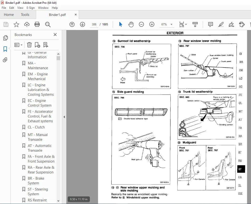
EXTERIOR 383
SEAT 388
Front Seat 388
Heated Seat 392
Rear Seat 393
SUNROOF 394
Trouble Diagnoese 398
WINDSHIELD AND WINDOWS 402
Windshield and Rear Window 403
MIRROR 404
Door Mirror 404
BODY ALIGNMENT 405
Engine Compartment 405
Underbody 407
CL 409
QUICK REFERENCE INDEX 0
TABLE OF CONTENTS 409
PRECAUTIONS AND PREPARATION 410
Precautions 410
Special Service Tools 410
NOISE, VIBRATION AND HARSHNESS (NVH) TROUBLESHOOTING 411
NVH Troubleshooting Chart 411
CLUTCH SYSTEM – Hydraulic Type 412
INSPECTION AND ADJUSTMENT 413
Adjusting Clutch Pedal 413
Bleeding Procedure 414
HYDRAULIC CLUTCH CONTROL 415
Clutch Master Cylinder 415
Operating Cylinder 416
CLUTCH RELEASE MECHANISM 417
CLUTCH DISC AND CLUTCH COVER 418
Clutch Disc 418
Clutch Cover and Flywheel 419
SERVICE DATA AND SPECIFICATIONS (SDS) 420
General Specifications 420
Inspection and Adjustment 420
EC 421
QUICK REFERENCE INDEX 0
TABLE OF CONTENTS 421
DIAGNOSTIC TROUBLE CODE INDEX 424
Alphabetical & P No Index for DTC 424
PRECAUTIONS AND PREPARATION 428
Special Service Tools 428
Commercial Service Tools 428
Supplemental Restraint System (SRS) “AIR BAG” 429
Precautions for On Board Diagnostic (OBD) System of Engine and A/T 429
Engine Fuel & Emission Control System 430
Precautions 431
ENGINE AND EMISSION CONTROL OVERALL SYSTEM 433
Circuit Diagram 433
System Diagram 434
ECCS Component Parts Location 435
Vacuum Hose Drawing 438
System Chart 439
ENGINE AND EMISSION BASIC CONTROL SYSTEM DESCRIPTION 440
Multiport Fuel Injection (MFI) System 440
Electronic Ignition (EI) System 442
Air Conditioning Cut Control 443
Fuel Cut Control (at no load & high engine speed) 444
EVAPORATIVE EMISSION SYSTEM 445
Description 445
Inspection 445
Evaporative Emission Line Drawing 448
POSITIVE CRANKCASE VENTILATION 450
Description 450
Inspection 450
BASIC SERVICE PROCEDURE 451
Fuel Pressure Release 451
Fuel Pressure Check 451
Injector Removal and and Installation 452
Fast Idle Cam (FIC) Inspection and Adjustment 453
Direct Ignition System – How to Check Idle Speed and Ignition Timing 453
Idle Speed/Ignition Timing/Idle Mixture Ration Adjustment 456
ON BOARD DIAGNOSTIC SYSTEM DESCRIPTION 463
Introduction 463
Two Trip Detection Logic 463
Emission-related Diagnostic Information 464
Malfunction Indicator Lamp (MIL) 476
OBD System Operation Chart 480
CONSULT 485
Generic Scan Tool (GST) 496
TROUBLE DIAGNOSIS – General Description 500
Introduction 500
Diagnostic Worksheet 500
Work Flow 502
Description for Work Flow 503
Basic Inspection 504
Diagnostic Trouble Code (DTC) Inspection Priority Chart 507
Fail-Safe Chart 508
Symptom Matrix Chart 509
CONSULT Reference Value in Data Monitor Mode 512
Major Sensor Reference Graph in Data Monitor Mode 515
ECM Terminals and Reference Value 517
TROUBLE DIAGNOSIS FOR INTERMITTENT INCIDENT 526
Description 526
Common I/I Report Situations 526
Diagnostic Procedure 526
TROUBLE DIAGNOSIS FOR POWER SUPPLY 527
Main Power Supply and Ground Circuit 527
DTC P0100, Mass Air Flow Sensor (MAFS) 532
DTC P0105, Absolute Pressure Sensor 539
DTC P0110, Intake Air Temperature Sensor 548
DTC P0115, Engine Coolant Temperature Sensor (ECTS) 554
DTC P0120, Throttle Position Sensor 559
DTC P0125, Engine Coolant Temperature Sensor (ECTS) 567
DTC P0130 (-B1), P0150 (-B2), Front Heated Oxygen Sensors (Front HO2S) (P0130: Right bank) (P0150: Left bank) (Circuit) 572
DTC P0131 (-B1), P0151 (-B2), Front Heated Oxygen Sensor (Lean shift monitoring) (Front HO2S) (P0131: Right bank), (P0151: Le 579
DTC P0132 (-B1), P0152 (-B2), Front Heated Oxygen Sensor (Rich shift monitoring) (Front HO2S) P0132: Right bank), (P0152: Lef 585
DTC P0133 (-B1), P0153 (-B2), Front Heated Oxygen Sensor (Response monitoring) (Front HO2S) (P0133: Right bank), (P0153: Left 591
DTC P0134 (-B1), P0154 (-B2), Front Heated Oxygen Sensor (High voltage) (Front HO2S) (P0134: Right bank), P0154: Left bank) 600
DTC P0135 (-B1), P0155 (-B2), Front Heated Oxygen Sensor (P0135: Right bank), (P0155: Left bank) 606
DTC P0137, Rear Heated Oxygen Sensor (Min Voltage Monitoring) (Rear HO2S) 611
DTC P0138, Rear Heated Oxygen Sensor (Max Voltage Monitoring) (Rear H2OS) 618
DTC P0139, Rear Heated Oxygen Sensor (Response Monitoring) (Rear HO2S) 625
DTC P0140, Rear Heated Oxygen Sensor (High Voltage) (Rear HO2S) 631
DTC P0141, Rear Heated Oxygen Sensor Heater 636
DTC P0171 (-B1), P0174 (-B2), Fuel Injection System Function (Lean side) (P0171: Right bank), (P0174: Left bank) 641
DTC P0172 (-B1), P0175 (-B2) Fuel Injection System Function (Rich side) (P0172: Right bank), (P0175: Left bank) 647
DTC P0180, Tank Fuel Temperature Sensor 653
DTC P0306 – P0300, No 6 – 1 Cylinder Misfire, Multiple Cylinder Misfire 657
DTC P0325, Knock Sensor (KS) 662
DTC P0335, Crankshaft Position Sensor (CKPS) (POS) 665
DTC P0340, Camshaft Position Sensor (CMPS) (PHASE) 671
DTC P0400, EGR Function (Close) 676
DTC P0402, EGRC-BPT Valve Funtion 685
DTC P0420, Three Way Catalyst Function 690
DTC P0440, Evaporative Emission (EVAP) Control System (Small Leak) (Negative Pressure) 694
DTC P0443, Evaporative Emission (EVAP) Canister Purge Volume Control Valve (Circuit) 704
DTC P0446, Evaporative Emission (EVAP) Canister Vent Volume Control Valve (Circuit) 710
DTC P0450, Evaporative Emission (EVAP) Control System Pressure Sensor 715
DTC P0500, Vehicle Speed Sensor (VSS) 721
DTC P0505, Idle Air Control Valve (IACV) – Auxiliary Air Control (AAC) Valve 725
DTC P0510 Closed Throttle Position Switch 731
DTC P0600, A/T Control 736
DTC P0605, Engine Control Module (ECM)-ECCS Control Module 740
DTC P1105, Manifold Absolute Pressure (MAP)/Barometric Pressure (BARO) Switch Solenoid Valve 742
DTC P1148 (-B1), P1168 (-B2), Closed Loop Control 749
DTC P1320, Ignition Signal 751
DTC P1335, Crankshaft Position Sensor (CKPS) (REF) 758
DTC P1336, Crankshaft Position Sensor (CKPS) (POS) (COG) 763
DTC P1400, EGRC-Solenoid Valve 769
DTC P1401, EGR Temperature Sensor 774
DTC P1402, EGR Function (Open) 779
DTC P1440, Evaporative Emission (EVAP) Control System (Small Leak) (Positive Pressure) 786
DTC P1444, Evaporative Emission (EVAP) Canister Purge Volume Control Valve 796
DTC P1446, Evaporative Emission (EVAP) Canister Vent Control Valve (Close) 803
DTC P1447, Evaporative Emission (EVAP) Control System Purge Flow Monitoring 808
DTC P1448, Evaporative Emission (EVAP) Canister Vent Control Valve (Open) 815
DTC P1490, Vacuum Cut Valve Bypass Valve (Circuit) 821
DTC P1491, Vacuum Cut Valve Bypass Valve 826
DTC P1492, Evaporative Emission (EVAP) Canister Purge Control Valve/Solenoid Valve (Circuit) 831
DTC P1493, Evaporative Emission (EVAP) Canister Purge Control Vlave/Solenoid Valve 837
DTC P1605, A/T Diagnosis Communication Line 844
DTC P1706, Park/Neutral Position Switch 847
TROUBLE DIAGNOSIS FOR OVERHEAT, Overheat 852
TROUBLE DIAGNOSIS FOR NON-DETECTABLE ITEMS 865
Injector 865
Start Signal 870
Fuel Pump Control 872
Front Engine Mounting Control 876
Power Steering Oil Pressure Switch 879
IACV-FICD Solenoid Valve 884
Electrical Load Signal 887
MIL & Data Link Connectors 890
SERVICE AND DATA SPECIFICATIONS (SDS) 891
General Specifications 891
Inspection and Adjustment 891
EL 893
QUICK REFERENCE INDEX 0
TABLE OF CONTENTS 893
PRECAUTIONS 896
Supplemental Restraint System (SRS) “AIR BAG” 896
HARNESS CONNECTOR 897
Description 897
STANDARDIZED RELAY 898
Description 898
POWER SUPPLY ROUTING 900
Schematic 900
Wiring Diagram – POWER – 901
Fuse 908
Fusible Link 908
Circuit Breaker Inspection 908
GROUND DISTRIBUTION 909
BATTERY 913
How to Handle Battery 913
Service Data and Specifications (SDS) 916
STARTING SYSTEM 917
System Description 917
Wiring Diagram – START – /M/T Models 919
Wiring Diagram – START – /A/T Models 920
Construction 921
Removal and Installation 921
Pinion/Clutch Check 922
Service Data and Specifications (SDS) 922
CHARGING SYSTEM 923
System Description 923
Wiring Diagram – CHARGE – 924
Trouble Diagnoses 925
Construction 925
Removal and Installation 925
Service Data and Specifications (SDS) 927
COMBINATION SWITCH 928
Check 928
Replacement 929
STEERING SWITCH 930
Check 930
HEADLAMP 931
System Description (For USA) 931
Wiring Diagram – H/LAMP – 932
Trouble Diagnoses 933
Bulb Replacement 934
Bulb Specifications 934
Aiming Adjustment 934
HEADLAMP – Daytime Light System – 936
System Description (For Canada) 936
Operation (For Canada) 937
Schematic 937
Wiring diagram – DTRL – 938
Trouble Diagnoses 941
Bulb Replacement 942
Aiming Adjustment 942
PARKING, LICENSE AND TAIL LAMPS 943
Wiring Diagram – TAIL/L– 943
STOP LAMPS 945
Wiring Diagram – STOP/L – 945
BACK-UP LAMP 947
Wiring Diagram – BACK/L – 947
FRONT FOG LAMP 948
System Description 948
Wiring Diagram – F/FOG – 949
Aiming Adjustment 950
Bulb Specifications 950
TURN SIGNAL AND HAZARD WARNING LAMPS 951
System Description 951
Wiring Diagram – TURN – 952
Trouble Diagnoses 954
Electrical Components Inspection 954
ILLUMINATION 955
System Description 955
Schematic 956
Wiring Diagram – ILL – 957
SPOT, VANITY MIRROR AND TRUNK ROOM LAMP 961
Wiring Diagram – INT/L – 961
METER AND GAUGES 962
System Description 962
Combination Meter 964
Wiring Diagram – METER – 965
Meter/Gauge Operation and Odo/Trip Meter Segment Check in Diagnosis Mode 966
Flexible Print Circuit (FPC) 967
Trouble Diagnoses 968
Electrical Components Inspection 972
WARNING LAMPS 974
Schematic 974
Wiring Diagram – WARN – 975
Electrical Components Inspection 979
WARN BUZZER 980
System Description 980
Wiring Diagram – BUZZER – 981
CONSULT 983
Trouble Diagnoses 984
WIPER AND WASHER 989
System Description 989
Wiring Diagram – WIPER – 991
CONSULT 993
Trouble Diagnoses 994
Removal and Installation 999
Washer Nozzle Adjustment1000
Check Valve (Built in washer nozzles)1000
HORN1001
Wiring Diagram – HORN –1001
CIGARETTE LIGHTER1002
Wiring Diagram – CIGAR –1002
CLOCK1003
Wiring Diagram – CLOCK –1003
REAR WINDOW DEFOGGER1004
System Description1004
Wiring Diagram – DEF –1005
CONSULT1007
Trouble Diagnoses1008
Filament Check1011
Filament Repair1012
AUDIO1013
System Description1013
Schematic/BOSE System1014
Wiring Diagram – AUDIO –/BOSE System1015
Wiring Diagram – AUDIO –/Base System1018
Trouble Diagnoses1020
AUDIO ANTENNA1022
System Description1022
Wiring Diagram – P/ANT –1023
Trouble Diagnoses1021
Location of Antenna1022
Antenna Rod Replacement1022
Window Antenna Repair1025
TELEPHONE (Pre wire)1027
Wiring Diagram – PHONE –1027
ELECTRIC SUNROOF1028
Wiring diagram – SROOF –1028
POWER SEAT1029
Wiring Diagram – SEAT –1029
HEATED SEAT1031
Wiring Diagram – HSEAT –1031
POWER DOOR MIRROR1032
Wiring Diagram – MIRROR –1032
TRUNK LID OPENER1033
Wiring Diagram – TLID –1033
AUTOMATIC SPEED CONTROL DEVICE (ASCD)1034
Component Parts and Harness Connector Location1034
System Description1035
Schematic/M/T Models1037
Schematic/A/T Models1038
Wiring Diagram – ASCD –1039
CONSULT1044
Fail-safe System1046
Trouble Diagnoses1048
Electrical Components Inspection1056
ASCD Wire Adjustment1057
IVMS (LAN)1058
Overall Description1058
Component Parts Location1059
System Diagram1060
Sleep/Wake-up Control1061
Fail-safe System1061
CONSULT1062
On-board Diagnosis1069
On-board Diagnosis – Mode I (IVMS communication diagnosis)1070
On-board Diagnosis – Mode II (Switch monitor)1072
Wiring Diagram – COMM –1074
Trouble Diagnoses1077
BCM (Body Control Module)1081
Schematic1081
Input/Output Operation Signal1082
DRIVER DOOR CONTROL UNIT (LCU01)1084
Schematic1084
Input/Output Operation Signal1085
PASSENGER DOOR CONTROL UNIT (LCU02)1086
Schematic1086
Input/Output Operation Signal1087
REAR PH/LH DOOR CONTROL UNIT (LCU03/04)1088
Schematic1088
Input/Output Operation Signal1090
MULTI-REMOTE CONTROL UNIT (LCU05)1091
Schematic1091
Input/Output Operation Signal1091
POWER WINDOW – IVMS1092
System Description1092
Schematic1093
Wiring Diagram – WINDOW –1093
CONSULT1098
On-board Diagmosis – Mode IV (Power window monitor)1099
Trouble Diagnoses1101
POWER DOOR LOCK – IVMS1107
System Description1107
Schematic1108
Wiring Diagram – D/LOCK –1109
CONSULT1113
On-board Diagnosis – Mode III (Power door lock operation)1116
Trouble Diagnoses1118
MULTI-REMOTE CONTROL SYSTEM – IVMS1126
System Description1126
Schematic1128
Wiring Diagram – MULTI –1129
CONSULT1134
Trouble Diagnoses1135
ID Code Entry Procedure1143
THEFT WARNING SYSTEM – IVMS1144
Component Parts and Harness Connector Location1144
System Description1144
Schematic1148
Wiring Diagram – THEFT –1150
CONSULT1157
Trouble Diagnoses1158
REAR POWER WINDOW SWITCH ILLUMINATION – IVMS1172
System Description1172
Wiring Diagram – SW/ILL –1173
CONSULT1173
Trouble Diagnoses1175
INTERIOR LAMP CONTROL – IVMS1176
System Desciption1176
Wiring Diagram – ROOM/L –1177
CONSULT1179
Trouble diagnoses1180
STEP LAMP – IVMS1184
System Description1184
Wiring Diagram – STEP/L –1185
CONSULT1187
Trouble Diagnoses1188
INTEGRATED HOMELINK TRANSMITTER1190
Wiring Diagram – TRNSMT –1190
Trouble Diagnoses1191
LOCATION OF ELECTRICAL UNITS1192
Engine Compartment1192
Passenger Compartment1193
Luggage Compartment1194
HARNESS LAYOUT1195
Outline1195
How to Read Harness Layout1196
Engine Room Harness1197
Main Harness1200
Engine Control Harness1202
Body Harness1204
Body No 2 Harness1206
Tail Hanress1206
Room Lamp Harness1207
Air Bag Harness1207
Door Harness (LH side)1208
Door Harness (RH side)1199
BULB SPECIFICATIONS1210
Headlamp1210
Exterior Lamp1210
Interior Lamp1210
WIRING DIAGRAM CODES (Cell codes)1211
SUPER MULTIPLE JUNCTION (SMJ) 0
Terminal Arrangement 1
FUSE BLOCK – Junction Box (J/B) 2
FUSE AND FUSIBLE LINK BOX 3
Terminal Arrangement 3
ELECTRICAL UNITS 4
Terminal Arrangement 4
JOIN CONNECTOR (J/C) 4
Terminal Arrangement 4
EM1213
QUICK REFERENCE INDEX 0
TABLE OF CONTENTS1213
PRECAUTIONS1214
Parts Requiring Angular Tightening1214
Liquid Gasket Application Procedure1214
PREPARATION1215
Special Service Tools1215
Commercial Service Tools1217
NOISE, VIBRATION AND HARSHNESS (NVH) TROUBLESHOOTING1218
NVH Troubleshooting Chart – Engine Noise1219
OUTER COMPONENT PARTS1220
COMPRESSION PRESSURE1224
Measurement of Compression Pressure1224
OIL PAN1225
Removal1225
Installation1228
TIMING CHAIN1231
Removal1233
Inspection1240
Installation1240
OIL SEAL REPLACEMENT1245
CYLINDER HEAD1248
Removal1249
Disassembly1249
Inspection1251
Assembly1256
Installation1256
VALVE CLEARANCE1261
Checking1261
Adjusting1262
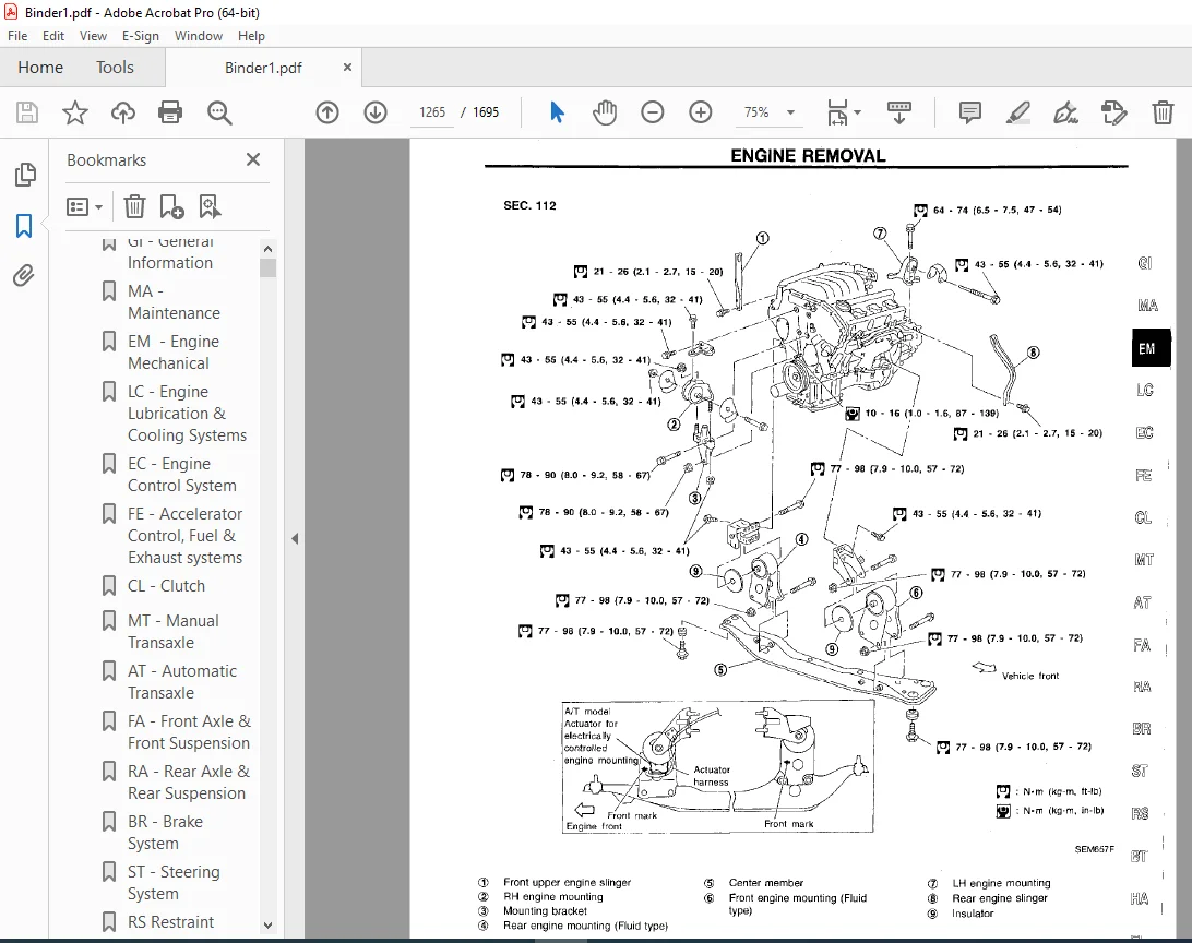
ENGINE REMOVAL1265
Removal1266
Installation1267
CYLINDER BLOCK1268
Disassembly1269
Inspection1269
Assembly1276
SERVICE DATA AND SPECIFICATIONS (SDS)1279
General Specifications1279
Inspection and Adjustment1279
FA1287
QUICK REFERENCE INDEX 0
TABLE OF CONTENTS1287
PRECAUTIONS AND PREPARATION1288
Precautions1288
Special Service Tools1288
Commercial Service Tools1289
NOISE, VIBRATION AND HARSHNESS (NVH) TROUBLESHOOTING1290
NVH Troubleshooting Chart1290
FRONT SUSPENSION SYSTEM1291
Components1291
ON-VEHICLE SERVICE1292
Front Axle and Front suspension Parts1292
Front Wheel Bearing1293
Front Wheel Alignment1293
Drive Shaft1294
FRONT AXLE1295
Wheel Hub and Knuckle1295
Drive Shaft1299
FRONT SUSPENSION1307
Components1307
Coil Spring and Strut Assembly1308
Stabilizer Bar1309
Transverse Link and Lower Ball Joint1310
SERVICE DATA AND SPECIFICATIONS (SDS)1312
General Specifications1312
Inspection and Adjustment1313
FE1314
QUICK REFERENCE INDEX 0
TABLE OF CONTENTS1314
PREPARATION/ACCELERATOR CONTROL SYSTEM1315
Special Service Tool1315
Adjusting Accelerator Wire1315
FUEL SYSTEM1316
EXHAUST SYSTEM1317
Foldout1318
QUICK REFERENCE INDEX 0
ELECTRICAL SYSTEM 2
SUPER MULTIPLE JUNCTION (SMJ)1318
INSTALLATION1318
Terminal Arrangement1319
FUSE BLOCK – Junction Box (J/B)1320
FUSE AND FUSIBLE LINK BOX1321
Terminal Arrangement1321
ELECTRICAL UNITS 1322
Terminal Arrangement1322
JOINT CONNECTOR (J/C)1323
Terminal Arrangement1323
GI1324
QUICK REFERENCE INDEX 0
TABLE OF CONTENTS1324
PRECAUTIONS1325
Supplemental Restraint System (SRS) “AIR BAG”1325
General Precautions1325
Precautions for Multiport Fuel Injection System or ECCS Engine1327
Precautions for Three Way Catalyst1328
Precautions for Engine Oils1328
Precautions for Fuel1329
Precautions for Air Conditioning1329
HOW TO USE THIS MANUAL1330
HOW TO READ WIRING DIAGRAMS1332
Sample/Wiring Diagram – EXAMPLE -1332
Description1334
HOW TO CHECK TERMINAL1339
Connector and Terminal Pin Kit1339
How to Probe Connectors1339
How to Check Enlarged Contact Spring of Terminal1340
Waterproof Connector Inspection1341
Terminal Lock Inspection1341
HOW TO PERFORM EFFICIENT DIAGNOSIS FOR AN ELECTRICAL INCIDENT1342
Work Flow1342
Incident Simulation Tests1343
Circuit Inspection1346
HOW TO FOLLOW FLOW CHART IN TROUBLE DIAGNOSES1352
How to Follow This Flow chart1353
CONSULT CHECKING SYSTEM1355
Function and System Application1355
Lithium Battery Replacement1355
Checking Equipment1355
Loading Procedure1356
CONSULT Data Link Connector (DLC) Circuit1356
INDENTIFICATION INFORMATION1357
Model Variation1357
Identification Number1358
Dimension1360
Wheels and Tires1360
LIFTING POINTS AND TOW TRUCK TOWING1361
Preparation1361
Board-on Lift1361
Garage Jack and Safety Stand1362
2-pole Lift1363
Tow Truck Towing1364
TIGHTENING TORQUE OF STANDARD BOLTS1365
SAE J1930 TERMINOLOGY LIST1366
SAE J1930 Terminology List1366
HA1370
QUICK REFERENCE INDEX 0
TABLE OF CONTENTS1370
MANUAL AND AUTO1372
PRECAUTIONS AND PREPARATION1372
Supplemental Restraint System (SRS) “AIR BAG”1372
Precautions for Working with HFC-134a (R134a)1373
General Refrigerant Precautions1373
Precautions for Refrigerant Connection1374
Precautions for Servicing Compressor1377
Special Service Tools1377
HFC-134A (R-134a) Service Tools and Equipment1378
Precautions for Service Equipment1380
DESCRIPTION1382
Refrigeration Cycle1382
V-6 Variable Displacement compressor1383
Component Layout1387
Discharge Air Flow1388
MANUAL1389
DESCRIPTION1389
Control Operation1389
TROUBLE DIAGNOSES1391
How to Perform Trouble Diagnoses for Quick and Accurate Repair1391
Operational Check1392
Symptom Chart1394
Preliminary Check1396
MANUAL AND AUTO1401
TROUBLE DIAGNOSES1401
Performance Test Diagnoses1401
Performance Chart1403
Trouble Diagnoses for Abnormal Pressure1404
MANUAL1407
TROUBLE DIAGNOSES1407
Harness Layout1407
Circuit Diagram1409
Wiring Diagram – A/C, M –1410
Main Power Supply and Ground Circuit Check1414
Diagnostic Procedure 11415
Diagnostic Procedure 21417
Diagnostic Procedure 31419
Diagnostic Procedure 41420
Diagnostic Procedure 51422
Electrical Components Inspection1425
Control Linkage Adjustment1426
AUTO1428
DESCRIPTION1428
Introduction1428
Features1428
Control Operation1431
TROUBLE DIAGNOSES1434
How to Perform Trouble Diagnoses for Quick and Accurate Repair1434
Operational Check1435
Symptom Chart1438
Self-diagnosis1440
Preliminary Check1450
Harness Layout1458
Circuit Diagram1460
Wiring Diagram – A/C, A –1461
Main Power Supply and Ground Circuit Check1464
Diagnostic Procedure 11465
Diagnostic Procedure 21466
Diagnostic Procedure 31467
Diagnostic Procedure 41468
Diagnostic Procedure 51469
Diagnostic Procedure 61470
Diagnostic Procedure 71472
Diagnostic Procedure 81473
Electrical Components Inspection1477
Control Linkage Adjustment1478
SYSTEM DESCRIPTION1479
Overview of Control System1479
Control System Input Components1480
Control System Automatic Amplifier (auto amp)1483
Control System Output Components1483
MANUAL AND AUTO1491
SERVICE PROCEDURES1491
HFC-134A (R134-a) Service Procedure1491
Maintenance of Lubricant Quantity in Compressor1492
Refrigerant Lines1495
Checking Refrigerant Leaks1498
Compressor Mounting1498
Belt Tension1498
Fast Idle Control Device (FICD)1498
Compressor1499
Compressor Clutch1499
SERVICE DATA AND SPECIFICATIONS (SDS)1503
General Specifications1503
Inspection and Adjustment1503
IDX1504
QUICK REFERENCE INDEX 0
LC1512
QUICK REFERENCE INDEX 0
TABLE OF CONTENTS1512
PRECAUTIONS AND PREPARATION1513
Liquid Gasket Application Procedure1513
Special Service Tools1514
ENGINE LUBRICATION SYSTEM1515
Lubrication Circuit1515
Oil Pressure Check1516
Oil Pump1516
ENGINE COOLING SYSTEM1519
Cooling Circuit1519
System Check1520
Water Pump1520
Thermostat1525
Radiator1526
Cooling Fan Control System1526
Radiator (Aluminum type)1527
Overheating Cause Analysis1530
SERVICE DATA AND SPECIFICATIONS (SDS)1531
Engine Lubrication System1531
Engine Cooling System1531
MA1532
QUICK REFERENCE INDEX 0
TABLE OF CONTENTS1532
PRECAUTIONS AND PREPARATION1533
Supplemental Restrain system (SRS) “AIR BAG”1533
Special Service Tool1533
GENERAL MAINTENANCE1534
PERIODIC MAINTENANCE1536
Schedule 11537
Schedule 21538
RECOMMENDED FLUIDS AND LUBRICANTS1539
Fluids and Lubricants1539
SAE Viscosity Number1539
Anti-freeze Coolant Mixture Ratio1540
ENGINE MAINTENANCE1541
Checking Drive Belts1541
Changing Engine Coolant1542
Checking Fuel Lines1543
Changing Fuel Filter1543
Changing Air Cleaner Filter1544
Changing Engine Oil1545
Changing Oil Filter1545
Changing Spark Plugs1546
Checking EVAP Vapor Lines1547
CHASSIS AND BODY MAINTENANCE1548
Checking Exhaust system1548
Checking Clutch Fluid Level and Leaks1548
Checking M/T Oil1548
Changing M/T Oil1548
Checking A/T Fluid1549
Changing A/T Fluid1549
Balancing Wheels1550
Tire Rotation1550
Checking Brake fluid Level and Leaks1550
Checking Brake Lines and Cables1550
Checking Disc Brake1550
Checking Steering Gear and Linkage1551
Checking Power Steering Fluid and Lines1551
Lubricating Locks, Hinges and Hood Latches1552
Checking Seat Belts, Buckles, Retractors, Anchors and Adjusters1552
SERVICE DATA AND SPECIFICATIONS (SDS)1553
Engine Maintenance1553
Chassis and Body Maintenance1553
MT1554
QUICK REFERENCE INDEX 0
TABLE OF CONTENTS1554
PREPARATION1555
Special Service Tools1555
Commercial Service Tools1557
NOISE, VIBRATION AND HARSHNESS (NVH) TROUBLESHOOTING1558
NVH Troubleshooting Chart1558
DESCRIPTION1559
Cross-sectional View1559
ON-VEHICLE SERVICE/REMOVAL AND INSTALLATION1560
Replacing Oil Seal1560
Position Switch Check1561
Viscous Coupling Check1561
Removal 1561
Installation1562
TRANSAXLE GEAR CONTROL1563
MAJOR OVERHAUL1564
Case Components1564
Gear Components1565
Shift Control Components1566
DISASSEMBLY1567
REPAIR FOR COMPONENT PARTS1570
Input Shaft and Gears1570
Mainshaft and Gears1575
Final Drive1579
Shift Control components1585
Case Components1585
ADJUSTMENT1586
Input Shaft End Play and Differential Side Bearing Preload1586
Mainshaft Bearing Preload1587
ASSEMBLY1590
SERVICE DATA AND SPECIFICATIONS (SDS)1594
General Specifications1594
Inspection and Adjustment1594
RA1599
QUICK REFERENCE INDEX 0
TABLE OF CONTENTS1599
PRECAUTIONS AND PREPARATION1600
Precautions1600
Special Service Tools1600
Commercial Service Tools1600
NOISE, VIBRATION AND HARSHNESS (NVH) TROUBLESHOOTING1601
NVH Troubleshooting Chart1601
REAR SUSPENSION SYSTEM1602
Components1602
ON-VEHICLE SERVICE1603
Rear Axle and Rear Suspension Parts1603
Rear Wheel Bearing1603
Rear Wheel Alignment1604
REAR AXLE1605
Wheel Hub1605
REAR SUSPENSION1608
Components1608
Removal and Installation1609
Coil Spring and Shock Absorber1609
Torsion Beam, Lateral Link and Control Rod1611
SERVICE DATA AND SPECIFICATIONS (SDS)1612
General Specifications1612
Inspection and Adjustment1612
RS1613
QUICK REFERENCE INDEX 0
TABLE OF CONTENTS1613
PRECAUTION1614
Supplemental Restraint System (SRS) “AIR BAG”1614
SEAT BELTS1615
Front Seat Belt1615
Rear Seat Belt1616
Seat Belt Inspection1617
SUPPLEMENTAL RESTRAINT SYSTEM (SRS)1620
Precaution for SRS “AIR BAG”1620
Special Service Tools1620
Description1621
SRS Component Parts Location1622
Maintenance Items1622
Removal and Installation – Diagnosis Sensor Unit and Satellite Sensor 1624
Removal – Air Bag Module and Spiral Cable1626
Removal – Front Passenger Air Bag Module1627
Removal – Side Air Bag Module1628
Installation – Air Bag Module and Spiral Cable1629
Installation – Front Passenger Air Bar Module1630
Installation – Side Air Bag Module1631
Disposal of Air Bag Module1631
TROUBLE DIAGNOSES – Supplemental Restrain System (SRS)1637
Trouble Diagnoses Introduction1637
How to Perform Trouble Diagnoses for Quick and Accurate Repair1639
Schematic1641
Wiring Diagram – SRS –1642
Self-diagnosis1645
Trouble diagnoses for Air Bag Warning Lamp1663
COLLISION DIAGNOSIS1665
ST1668
QUICK REFERENCE INDEX 0
TABLE OF CONTENTS1668
PRECAUTIONS AND PREPARATION1669
Supplemental Restraint System (SRS) “AIR BAG”1669
Precautions for Steering System1669
Special Service Tools1670
Commercial Service Tools1671
NOISE, VIBRATION AND HARSHNESS (NVH) TROUBLESHOOTING1672
NVH Troubleshooting Chart1672
ON-VEHICLE SERVICE1673
Checking Steering Wheel Play1673
Checking Neutral Position on Steering Wheel1673
Front Wheel Turning Angle1673
Checking Gear Housing Movement1673
Checking and Adjusting Drive Belts1674
Checking Fluid Level1674
Checking Fluid Leakage1674
Bleeding Hydraulic System1674
Checking Steering Wheel Turning Force1675
Checking Hydraulic System1676
STEERING WHEEL AND STEERING COLUMN1677
Removal and Installation1677
Disassembly and Assembly1679
Inspection1680
POWER STEERING GEAR AND LINKAGE1681
Removal and Installation1681
Components1683
Disassembly1684
Inspection1685
Assembly1685
Adjustment1690
POWER STEERING OIL PUMP1691
Pre-disassembly Inspection1691
Disassembly1692
Inspection1692
Assembly1693
SERVICE DATA AND SPECIFICATIONS (SDS)1694
General Specifications1694
Inspection and Adjustment1694
DESCRIPTION:
1998 NISSAN MAXIMA A32 Series Service Manual PDF DOWNLOAD
FOREWORD
- This manual contains maintenance and repair procedures for the 1998 Nissan MAXIMA.
- In order to assure your safety and the efficient functioning of the vehicle, this manual should be read thoroughly.
- It is especially important that the PRECAUTIONS in the GI section be completely understood before starting any repair task.
- All information in this manual is based on the latest product information at the time of publication. The right is reserved to make changes in specifications and methods at any time without notice.
IMPORTANT SAFETY NOTICE
- The proper performance of service is essential for both the safety of the technician and the efficient functioning of the vehicle.
- The service methods in this Service Manual are described in such a manner that the service may be performed safely and accurately.
- Service varies with the procedures used, the skills of the technician and the tools and parts available.
- Accordingly, anyone using service procedures, tools or parts which are not specifically recommended by NISSAN must first be completely satisfied that neither personal safety nor the vehicle’s safety will be jeopardized by the service method selected.
PLEASE NOTE:
- This is the same manual used by the dealers to diagnose and troubleshoot your vehicle
- You will be directed to the download page as soon as the purchase is completed. The whole payment and downloading process will take anywhere between 2-5 minutes
- Need any other service / repair / parts manual, please feel free to contact [email protected] . We still have 50,000 manuals unlisted
G.P