Trusted Business
Verified & Licensed
Virus Free Files
100% Safe Downloads
Secure Payment
SSL Protected
Instant Delivery
Available Immediately
1998 NISSAN QUEST V40 Series Service Manual PDF DOWNLOAD
$24.95
1998 NISSAN QUEST V40 Series Service Manual PDF DOWNLOAD
Instant PDF Download
Available immediately
Save to Your Device
Download & keep forever
Antivirus Scanned
100% virus-free
Trusted Worldwide
175,000+ customers
Description
1998 NISSAN QUEST V40 Series Service Manual PDF DOWNLOAD
FILE DETAILS:
1998 NISSAN QUEST V40 Series Service Manual PDF DOWNLOAD
Language : English
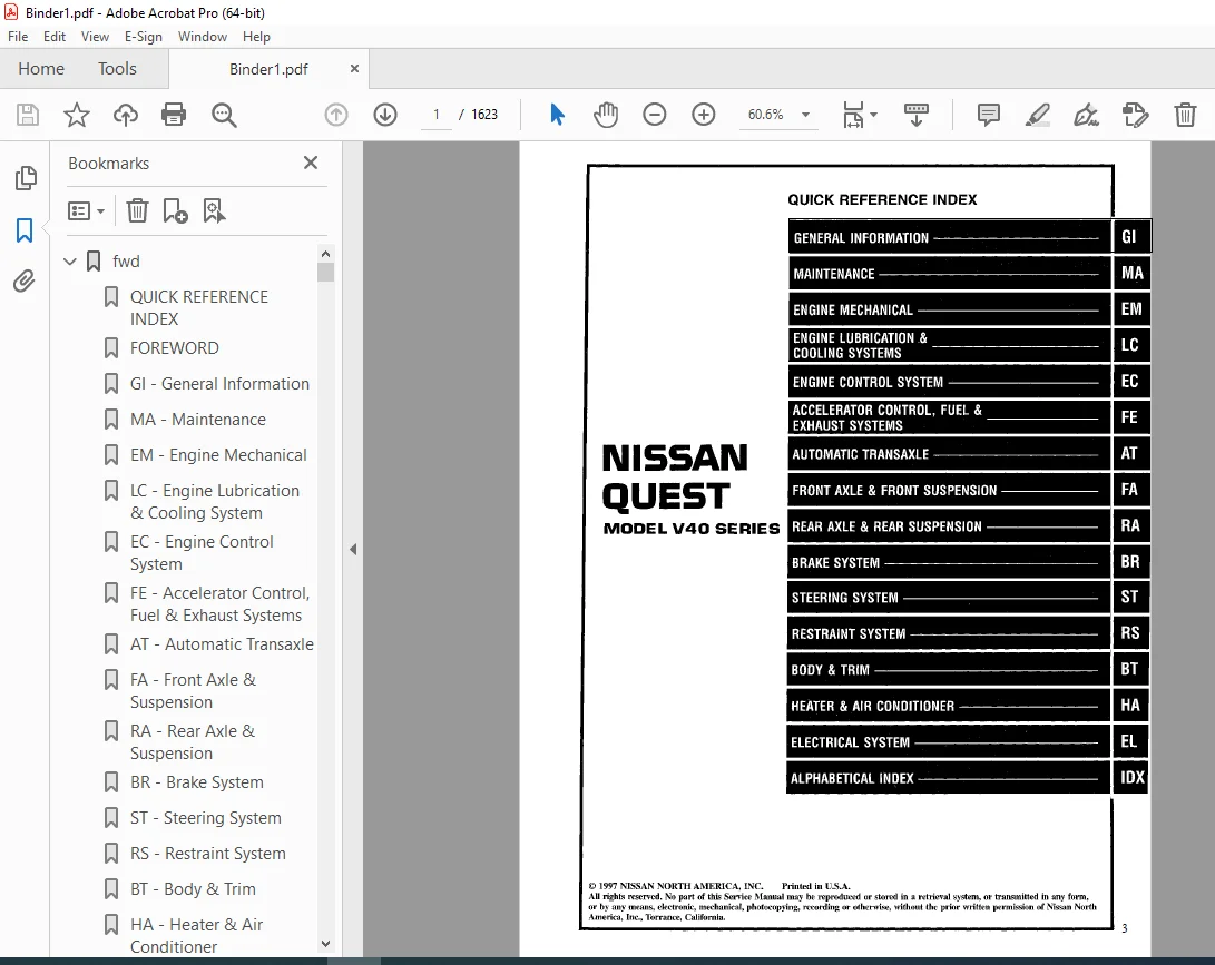
Pages : 1623
downloadable : Yes
File type : PDF
IMAGES PREVIEW OF THE MANUAL:
TABLE OF CONTENTS:
1998 NISSAN QUEST V40 Series Service Manual PDF DOWNLOAD
fwd............................................................................................................................   1
	QUICK REFERENCE INDEX......................................................................................................   1
	FOREWORD...................................................................................................................   2
	GI - General Information...................................................................................................   0
	MA - Maintenance...........................................................................................................   0
	EM - Engine Mechanical.....................................................................................................   0
	LC - Engine Lubrication & Cooling System...................................................................................   0
	EC - Engine Control System.................................................................................................   0
	FE - Accelerator Control, Fuel & Exhaust Systems...........................................................................   0
	AT - Automatic Transaxle...................................................................................................   0
	FA - Front Axle & Suspension...............................................................................................   0
	RA - Rear Axle & Suspension................................................................................................   0
	BR - Brake System..........................................................................................................   0
	ST - Steering System.......................................................................................................   0
	RS - Restraint System......................................................................................................   0
	BT - Body & Trim...........................................................................................................   0
	HA - Heater & Air Conditioner..............................................................................................   0
	EL - Electrical System.....................................................................................................   0
	IDX - Alphabetical Index...................................................................................................   1
	Foldout....................................................................................................................   0
	Comment Sheet..............................................................................................................   3
	Quick Reference Chart......................................................................................................   4
	GST Mode 6 - Test Value & Test Limit Chart.................................................................................   5
at.............................................................................................................................   6
	QUICK REFERENCE INDEX......................................................................................................   0
	TABLE OF CONTENTS..........................................................................................................   6
	DIAGNOSTIC TROUBLE CODE INDEX..............................................................................................   8
		Alphabetical & P No. Index For DTC.....................................................................................   8
	PRECAUTIONS AND PREPARATION................................................................................................   9
		Supplemental Restraint System (SRS) "AIR BAG"..........................................................................   9
		Precautions for On Board Diagnostic (OBD) System of A/T and Engine.....................................................   9
		Precautions............................................................................................................  11
		Service Notice or Precautions..........................................................................................  11
		Special Service Tools..................................................................................................  13
		Commercial Service Tools...............................................................................................  16
	OVERALL SYSTEM.............................................................................................................  17
		A/T Electrical Parts Location..........................................................................................  17
		Circuit Diagram for Quick Pinpoint check...............................................................................  18
		Wiring Diagram - A/T -.................................................................................................  19
		Cross-sectional View...................................................................................................  25
		Hydraulic Control Circuit..............................................................................................  26
		Shift Mechanism........................................................................................................  27
		Control System.........................................................................................................  36
		Control Mechanism......................................................................................................  38
		Control Valve..........................................................................................................  43
	ON BOARD DIAGNOSTIC SYSTEM DESCRIPTION.....................................................................................  44
		Introduction...........................................................................................................  44
		OBD-II Function for A/T System.........................................................................................  44
		One or Two Trip Detection Logic of OBD-II..............................................................................  44
		OBD - II Diagnostic Trouble Code (DTC).................................................................................  44
		Malfunction Indicator Lamp (MIL).......................................................................................  48
		CONSULT................................................................................................................  48
		Self-diagnosis.........................................................................................................  56
			SELF-DIAGNOSTIC PROCEDURE - (No Tools).............................................................................  56
		Diagnostic Procedure without CONSULT...................................................................................  57
	TROUBLE DIAGNOSIS - Introduction...........................................................................................  59
		Introduction...........................................................................................................  59
		Diagnostic Worksheet...................................................................................................  60
		Work Flow..............................................................................................................  63
	TROUBLE DIAGNOSIS - Basic Inspeciton.......................................................................................  64
		A/T Fluid Check........................................................................................................  64
		Stall Test.............................................................................................................  64
		Pressure Test..........................................................................................................  67
		Road Test..............................................................................................................  68
	TROUBLE DIAGNOSES - General Description....................................................................................  79
		Symptoms Chart.........................................................................................................  79
		TCM Terminals and Reference Value......................................................................................  82
	DTC P0705, Inhibitor Switch................................................................................................  87
	DTC P0710, A/T Fluid Temperature Sensor....................................................................................  91
	DTC P0720, Vehicle Speed Sensor-A/T (Revolution sensor)....................................................................  95
	DTC P0725, Engine Speed Signal.............................................................................................  99
	DTC P0731, A/T 1st Gear Function...........................................................................................  44
	DTC P0732, A/T 2nd Gear Function........................................................................................... 108
	DTC P0733, A/T 3rd Gear Function........................................................................................... 113
	DTC P0734, A/T 4TH Gear Function........................................................................................... 118
	DTC P0740, Torque Converter Clutch Solenoid Valve.......................................................................... 126
	DTC P0744, A/T TCC S/V Function (Lock-up).................................................................................. 130
	DTC P0745, Line Pressure Solenoid Valve.................................................................................... 137
	DTC P0750, Shift Solenoid Valve A.......................................................................................... 141
	DTC P0755, Shift Solenoid Valve B.......................................................................................... 145
	DTC P1705, Throttle Position Sensor........................................................................................ 149
	DTC P1760, Overrun Clutch Solenoid Valve................................................................................... 156
	TROUBLE DIAGNOSES FOR BATT/FLUID TEM SEN................................................................................... 160
		A/T Fluid Temperature Sensor Circuit ;and TCM Power Source............................................................. 160
	TROUBLE DIAGNOSES FOR VHCL SPEED SEN-MTR................................................................................... 164
		Vehicle Speed Sensor-MTR............................................................................................... 164
		1. O/D OFF Indicator Lamp does Not Come On............................................................................. 167
		2. Engine Cannot Be Started in "P" and "N" Position.................................................................... 168
		3. In "P" Position Vehicle Moves Forward or Backward When Pushed....................................................... 168
		4. In "N" Position Vehicle Moves....................................................................................... 169
		5. Large Shock "N"  -  "R" Position.................................................................................... 170
		6.  Vehicle Does Not Creep Forward In "D", "2" or "1" Position......................................................... 171
		7. Vehicle Does Not Creep Forward in "D", "2" or "1" Position.......................................................... 172
		8. Vehicle Cannot Be Started From D1................................................................................... 173
		9. A/T Does Not Shift: D1 - D2 or Does Not Kickdown: D4 - D2........................................................... 174
		10. A/T Does Not Shift D2 - D3......................................................................................... 175
		11. A/T Does Not Shift: D3 - D4........................................................................................ 176
		12. A/T Does Not Perform Lock-up....................................................................................... 177
		13. A/T Does Not Hold Lock-up condition................................................................................ 179
		14. Lock - up Is Not Released.......................................................................................... 179
		15. Engine Speed Does Not Return To Idle (Light Braking D4 - D3)....................................................... 179
		16. Vehicle Does Not Start: D4 - 22, When Selector Lever "D" - "2" Position............................................ 180
		17. A/T Does Not Shift: D4 - D3, When Overdrive Control Switch " ON" - "OFF"........................................... 180
		18. A/T Does Not Shift: D3 - 22. When Selector Lever "D" - "2" Position................................................ 181
		19. A/T Does Not Shift: 22 - 11, When Selector Lever "2" - "1" Position................................................ 181
		20. Vehicle Does Not Decelerate By Engine Brake........................................................................ 182
		21. TCM Self-diagnosis Does Not Activate (inhibitor, Overdrive Control and Throttle Position Switch Circuit Checks).... 182
	TROUBLE DIAGNOSES - A/T Shift Lock System.................................................................................. 190
		Description............................................................................................................ 190
		Shift Lock System Electrical Parts Location Removal - Shift Lock Solenoid.............................................. 190
		Wiring Diagram - SHIFT................................................................................................. 191
		Diagnostic Procedure................................................................................................... 192
		Shift Lock Rod......................................................................................................... 194
		Component Check........................................................................................................ 195
	ON -VEHICLE SERVICE........................................................................................................ 196
		Control Valve Assembly and Accumulator................................................................................. 196
		Revolution Sensor Replacement.......................................................................................... 197
		Inhibitor Switch Adjustment............................................................................................ 197
		Control Cable Adjustment............................................................................................... 198
		Differential Side Oil Seal Replacement................................................................................. 198
	REMOVAL AND INSTALLATION................................................................................................... 199
		Removal................................................................................................................ 199
		Installation........................................................................................................... 200
	MAJOR OVERHAUL............................................................................................................. 202
		Locations of Adjusting Shims, Needle Bearings, Thrust Washers and Snap Rings........................................... 205
		Oil Channel............................................................................................................ 206
	DISASSEMBLY................................................................................................................ 207
	REPAIR FOR COMPONENT PARTS................................................................................................. 221
		Manual Shaft........................................................................................................... 221
		Oil Pump............................................................................................................... 223
		Control Valve Assembly................................................................................................. 227
		Control Valve Upper Body............................................................................................... 235
		Control Valve Lower Body............................................................................................... 239
		Reverse Clutch......................................................................................................... 241
		High Clutch............................................................................................................ 244
		Forward Clutch and Overun Clutch....................................................................................... 248
		Low & Reverse Brake.................................................................................................... 254
		Rear Internal Gear, Forward Clutch Hub and Overun Clutch Hub........................................................... 256
		Output Shaft, Idler Gear, Reduction Pinion Gear and Bearing Retainter.................................................. 260
		Band Servo Piston Assembly............................................................................................. 265
		Final Drive............................................................................................................ 270
	ASSEMBLY................................................................................................................... 274
		Assembly 1............................................................................................................. 274
		Adjustment 1........................................................................................................... 274
		Assembly 2............................................................................................................. 279
		Adjustment 2........................................................................................................... 285
		Assembly 3............................................................................................................. 287
	SERVICE DATA AND SPECIFICATIONS (SDS)...................................................................................... 293
br............................................................................................................................. 300
	QUICK REFERENCE INDEX......................................................................................................   0
	TABLE OF CONTENTS.......................................................................................................... 300
	PRECAUTIONS AND PREPARATION................................................................................................ 301
		Supplemental Restraint System (SRS) "AIR BAG".......................................................................... 301
		Precautions for Brake System........................................................................................... 301
		Commercial Service Tools............................................................................................... 301
	NOISE, VIBRATION AND HARSHNESS (NVH) TROUBLESHOOTING....................................................................... 302
		NVH Troubleshooting Chart.............................................................................................. 302
	CHECK AND ADJUSTMENT....................................................................................................... 303
		Checking Brake Fluid Level............................................................................................. 303
		Checking Brake Line.................................................................................................... 303
		Changing Brake Fluid................................................................................................... 303
	AIR BLEEDING............................................................................................................... 304
		Bleeding Procedure..................................................................................................... 304
	BRAKE HYDRAULIC LINE....................................................................................................... 305
	CONTROL VALVE.............................................................................................................. 307
		Dual Load Sensing Valve................................................................................................ 307
	BRAKE PEDAL AND BRACKET.................................................................................................... 310
		Removal and Installation............................................................................................... 310
		Inspection............................................................................................................. 310
		Adjustment............................................................................................................. 311
	MASTER CYLINDER............................................................................................................ 312
	BRAKE BOOSTER.............................................................................................................. 315
	VACUUM HOSE................................................................................................................ 317
	FRONT DISC BRAKE........................................................................................................... 318
	REAR DRUM BRAKE............................................................................................................ 322
	PARKING BRAKE CONTROL...................................................................................................... 336
	ANTI-LOCK BRAKE SYSTEM..................................................................................................... 328
		Purpose................................................................................................................ 328
		Operation.............................................................................................................. 328
		System Components...................................................................................................... 329
		System Description..................................................................................................... 329
		Removal and Installation............................................................................................... 330
			Front Wheel Sensor................................................................................................. 330
			Rear Wheel Sensor.................................................................................................. 330
			ABS Actuator....................................................................................................... 331
			Control Unit....................................................................................................... 333
			ABS Relays......................................................................................................... 333
	TROUBLE DIAGNOSES.......................................................................................................... 334
		How to Perform Trouble Diagnoses for Quick and Accurate Repair......................................................... 334
		Preliminary Check...................................................................................................... 335
		Component Parts Location and Harness Layout............................................................................ 336
		Circuit Diagram........................................................................................................ 337
		Wiring Diagram - ABS -................................................................................................. 338
		Self-diagnosis......................................................................................................... 342
			Function........................................................................................................... 342
			Self-Diagnosis Procedure........................................................................................... 342
			How to Read Self-Diagnostic Results (Malfunction Codes)............................................................ 343
			How to Erase Self-Diagnostic Results (Malfunction Codes)........................................................... 343
			Malfunction Code/Symptom Chart..................................................................................... 344
		Ground Circuit Check................................................................................................... 345
	TROUBLE DIAGNOSES FOR SELF-DIAGNOSTIC ITEM................................................................................. 346
		Diagnostic Procedure 1. ABS Control Actuator Solenoid Valve............................................................ 346
		Diagnostic Procedure 2. Wheel Sensor or Rotor.......................................................................... 348
		Diagnostic Procedure 3. Motor Relay or Motor........................................................................... 350
		Diagnostic Procedure 4. Solenoid Valve Relay........................................................................... 353
		Diagnostic Procedure 5. Control Unit................................................................................... 355
	TROUBLE DIAGNOSES FOR SYMPTOM.............................................................................................. 356
		Diagnostic Procedure 6. Warning Lamp Does Not Come On.................................................................. 356
		Diagnostic Procedure 7. Warning Lamp Stays On.......................................................................... 358
		Diagnostic Procedure 8. Pedal Vibration and Noise...................................................................... 361
		Diagnostic Procedure 9. Long Stopping Distance......................................................................... 362
		Diagnostic Procedure 10. Unexpected Pedal Action....................................................................... 362
		Diagnostic Procedure 11. ABS Does Not Work............................................................................. 363
		Diagnostic Procedure 12. ABS Works Frequently.......................................................................... 363
	SERVICE DATA AND SPECIFICATIONS (SDS)...................................................................................... 364
bt............................................................................................................................. 365
	QUICK REFERENCE INDEX......................................................................................................   0
	TABLE OF CONTENTS.......................................................................................................... 365
	PRECAUTIONS................................................................................................................ 366
		Supplemental Restraint System (SRS) "AIR BAG".......................................................................... 365
	GENERAL SERVICING.......................................................................................................... 367
		Clip and Fastener...................................................................................................... 370
	BODY END................................................................................................................... 370
		Body Front End......................................................................................................... 370
			Removal - Front bumper assembly.................................................................................... 370
			Bumper Shock Absorber Inspection................................................................................... 373
		Body Rear End and Opener............................................................................................... 374
			Removal - Rear bumper assembly..................................................................................... 374
			Bumper Shock Absorber Inspection - Rear............................................................................ 374
	DOOR....................................................................................................................... 377
		Front Door............................................................................................................. 377
		Sliding Door........................................................................................................... 378
		Rear Door.............................................................................................................. 380
	INSTRUMENT PANEL........................................................................................................... 382
	INTERIOR TRIM.............................................................................................................. 386
		Side and Floor Trim.................................................................................................... 386
		Roof Trim.............................................................................................................. 390
	EXTERIOR................................................................................................................... 392
		)1) Hood front sealing rubber.......................................................................................... 393
		(2) (3) Hood rear sealing rubber and cowl top grille................................................................... 393
		(4) Sun roof frame weatherstrip and sun roof lid weatherstrip.......................................................... 393
		(5) Windshield upper molding........................................................................................... 393
		(6) Windshield side molding............................................................................................ 393
		(7) Body side drip molding............................................................................................. 394
		(8) Waist rail finisher................................................................................................ 394
		(9) Front door weatherstrip............................................................................................ 394
		(10) Sliding door weatherstrip......................................................................................... 394
		(11) Sliding door lower seal........................................................................................... 394
		(12) Back door opening weatherstrip.................................................................................... 394
		(13) Luggage rack...................................................................................................... 395
		(14) Outside door molding.............................................................................................. 396
		(15) Front door corner covers.......................................................................................... 397
		(16) Side guard molding................................................................................................ 397
	SEAT....................................................................................................................... 398
		Front Seat............................................................................................................. 398
		Front Power Seat....................................................................................................... 399
		2nd Seat............................................................................................................... 400
		3rd Seat............................................................................................................... 402
	SUNROOF.................................................................................................................... 407
		Trouble Diagnoses...................................................................................................... 410
	WINDSHIELD AND WINDOWS..................................................................................................... 415
		Windshield and Rear Window............................................................................................. 416
			Repairing Water Leaks For Windshield............................................................................... 416
		Side Window (1st)...................................................................................................... 417
		Side Window (2nd)...................................................................................................... 418
	MIRROR..................................................................................................................... 419
		Door Mirror............................................................................................................ 419
		Rearview Mirror........................................................................................................ 420
	BODY ALIGNMENT............................................................................................................. 421
		Engine Compartment..................................................................................................... 422
		Underbody.............................................................................................................. 424
ec............................................................................................................................. 427
	QUICK REFERENCE INDEX......................................................................................................   0
	TABLE OF CONTENTS.......................................................................................................... 427
	DIAGNOSTIC TROUBLE CODE INDEX.............................................................................................. 430
		Alphabetical & P No. Index for DTC..................................................................................... 430
	PRECAUTIONS AND PREPARATION................................................................................................ 432
		Special Service Tool................................................................................................... 432
		Commercial Service Tools............................................................................................... 432
		Supplemental Restraint System (SRS) "AIR BAG" ......................................................................... 433
		Precautions for On Board Diagnostic (OBD) System of Engine and  A/T.................................................... 433
		Engine Fuel & Emission Control System.................................................................................. 432
		Precautions............................................................................................................ 435
	ENGINE AND EMISSION CONTROL OVERALL SYSTEM................................................................................. 437
		Circuit Diagram........................................................................................................ 437
		ECCS Component Parts Location.......................................................................................... 438
		System Diagram......................................................................................................... 441
		Vacuum Hose Drawing.................................................................................................... 443
		System Chart........................................................................................................... 445
	ENGINE AND EMISSION BASIC CONTROL SYSTEM DESCRIPTION....................................................................... 446
		Multiport Fuel Injection (MFI) System ................................................................................. 446
		Distributor Ignition (DI) System....................................................................................... 448
		Air Conditioning Cut Control........................................................................................... 449
		Fuel Cut Control....................................................................................................... 450
	EVAPORATIVE EMISSION SYSTEM................................................................................................ 451
		Description............................................................................................................ 451
		Inspection............................................................................................................. 452
		Evaporative Emission Line Drawing (for California)..................................................................... 455
	POSITIVE CRANKCASE VENTILATION............................................................................................. 457
		Description............................................................................................................ 457
		Inspection............................................................................................................. 457
	BASIC SERVICE PROCEDURE.................................................................................................... 458
		Fuel Presssure Release................................................................................................. 458
		Fuel Pressure Check.................................................................................................... 458
		Fuel Presssure Regulator Check......................................................................................... 459
		Injector Removal and Installation...................................................................................... 459
		Fast Idle Cam (FIC).................................................................................................... 460
		Idle Speed/Ignition Timing/Idle Mixture Ratio Adjustment............................................................... 462
	ON BOARD DIAGNOSTIC SYSTEM DESCRIPTION..................................................................................... 468
		Introduction........................................................................................................... 468
		Two Trip Detection Logic............................................................................................... 468
		Emission-related Diagnostic Information................................................................................ 469
		Malfunction Indicatior Lamp (MIL)...................................................................................... 478
		OBD System Operation Chart............................................................................................. 483
		CONSULT................................................................................................................ 488
		Generic Scan Tool (GST)................................................................................................ 500
	TROUBLE DIAGNOSIS - Introduction........................................................................................... 502
		Introduction........................................................................................................... 502
		Diagnosis Worksheet.................................................................................................... 502
	TROUBLE DIAGNOSIS - Basic Inspection....................................................................................... 506
		Basic Inspection....................................................................................................... 506
	TROUBLE DIAGNOSIS - General Description.................................................................................... 509
		Diagnositc Trouble Code (DTC) Inspection Priority Chart................................................................ 509
		Fail-Safe Chart........................................................................................................ 510
		Symptom Matrix Chart................................................................................................... 511
		CONSULT Reference Value in Data Monitor Mode........................................................................... 514
		Major Sensor Reference Graph in Data Monitor Mode...................................................................... 516
		ECM Terminals and Reference Value...................................................................................... 518
	TROUBLE DIAGNOSIS FOR INTERMITTENT INCIDENT................................................................................ 527
		Description............................................................................................................ 527
		Common I/I Report Situations........................................................................................... 527
		Diagnostic Procedure................................................................................................... 527
	TROUBLE DIAGNOSIS FOR POWER SUPPLY......................................................................................... 528
		Main Power Supply and Ground Circuit................................................................................... 528
	DTC P0100, Mass Air Flow Sensosr (MAFS).................................................................................... 532
	DTC P0105, Absolute Pressure Sensor (For California)....................................................................... 541
	DTC P0110, Intake Air Temperature Sensor................................................................................... 549
	DTC P0115, Engine Coolant Temperature Sensor (ECTS) Circuit................................................................ 555
	DTC P0120, Throttle Position Sensor........................................................................................ 560
	DTC P0125, Engine Coolant Temperture (ECT) Sensor.......................................................................... 572
	DTC P0130, Front Heated Oxygen Sensor (Circuit) Front H02S)................................................................ 577
	DTC P0131, Front Heated Oxygen Sensor (Lean Shift Monitioring) (Front HO2S)................................................ 583
	DTC P0132, Front Heated Oxygen Sensor (Rich Shift Moitoring) (Front HO2S).................................................. 589
	DTC P0133, Front Heated Oxygen Sensor (Response Monitoring) (Front H02S)................................................... 595
	DTC P0134, Front Heated Oxygen Sensor (High Voltage) (Front H02S).......................................................... 603
	DTC P0135, Fron Heated Oxygen Sensor Heater................................................................................ 608
	DTC P0137, Rear Heated Oxygen Sensor (Min. Voltage Monitoring) (Rear H02S)................................................. 612
	DTC P0138, Rear Heated Oxygen Sensor (Max. Voltage Monitoring) (Rear H02S)................................................. 619
	DTC P0139, Rear Heated Oxygen Sensor (Response Monitoring) (Rear H02S)..................................................... 626
	DTC P0140, Rear Heated Oxygen Sensor (High Voltage) (Rear H02S)............................................................ 632
	DTC P0141, Rear Heated Oxygen Sensor Heater................................................................................ 637
	DTC P0171, Fuel Injection System Function (Lean side)...................................................................... 641
	DTC P0172, Fuel Injection System Function (Rich side)...................................................................... 647
	DTC P0180 Tank Fuel Temperature Sensor (For California).................................................................... 653
	DTC P0300 - P0306, No.6 - 1 Cylinder Misfire, Multiple Cylinder Misfire.................................................... 657
	DTC P0325, Knock Sensor (KS)............................................................................................... 662
	DTC P0335, Crankshaft Position Sensor (CKPS) (OBD)......................................................................... 666
	DTC P0340, Camshaft Position Sensor (CMPS)................................................................................. 671
	DTC P0400, EGR Funcion (Close)............................................................................................. 677
	DTC P0402, EGRC-BPT Valve Function......................................................................................... 685
	DTC P0420, Three Way Catalyst Function..................................................................................... 690
	DTC P0440, Evaporative Emission (EVAP) Control System (Small Leak) (Negative Pressure) (For California).................... 695
	DTC P0443, Evaporative Emission (EVAP) Canister Purge Volume Contol Valve (for California)................................. 704
	DTC P0446, Evaporative Emission (EVAP) Canister Vent Control Valve (Circuit) (For California).............................. 710
	DTC P0450, Evaporative Emission (EVAP) Control System Presssure Sensor (For Calfornia)..................................... 715
	DTC P0500, Vehicle Speed Sensor (VSS)...................................................................................... 721
	DTC P0505, Idle Air Control Valve (IACV) - Auxiliary Air Control (AAC) Valve............................................... 725
	DTC P0510, Closed Throttle Position Switch................................................................................. 731
	DTC P0600, A/T Control..................................................................................................... 736
	DTC P0605, Engine Control Module (ECM)..................................................................................... 739
	DTC P1105, Manifold Absolute Pressure (MAP)/ Barometric Pressure (BARO) Switch Solenoid Valve (For California)............. 741
	DTC P1148, Closed Loop Control............................................................................................. 749
	DTC P1320, Ignition Signal................................................................................................. 751
	DTC P1336, Crankshaft Position Sensor (CKPS) (OBD) (COG)................................................................... 757
	DTC P1400, EGRC -Solenoid Valve............................................................................................ 762
	DTC P1401, EGR Temperature Sensor.......................................................................................... 766
	DTC P1402, EGR Function (Open)............................................................................................. 772
	DTC P1440, Evaporative Emission (EVAP) Control System (Small Leak) (Positive Pressure) (For California).................... 779
	DTC P1444, Evaporative Emission (EVAP) Canister Purge Volume Control Valve (for California)................................ 789
	DTC P1446, Evaporative Emission (EVAP) Canister Vent Control Valve (Close) (For California)................................ 797
	DTC P1447, Evaporative Emission (EVAP) Control System Purge Flow Monitoring (For Calfornia)................................ 801
	DTC P1448, Evaporative Emission (EVAP) Canister Vent Control Valve (Open) (For California)................................. 808
	DTC P1490, Vacuum Cut Valve Bypass Valve (For California).................................................................. 813
	DTC P1491, Vacuum Cut Valve Bypass Valve (For California).................................................................. 818
	DTC P1492, Evaporative Emission (EVAP) Canister Purge Control Valve/Solenoid Valve (Circuit) (For California).............. 823
	DTC P1493, Evaporative Emission (EVAP) Canister Purge Contol Valve Solenoid Valve (For California)......................... 828
	DTC P1605, A/T Diagnosis Commuinication Line............................................................................... 835
	DTC P1706, Park/Neutral Position Switch.................................................................................... 838
	TROUBLE DIAGNOSIS FOR NON-DETECTABLE ITEMS................................................................................. 854
		Injector............................................................................................................... 854
		Start Signal........................................................................................................... 857
		Fuel Pump.............................................................................................................. 860
		Power Steering Oil Pressure Switch..................................................................................... 866
		IACV-FICD Solenoid Valve/Air Conditioning System Input................................................................. 870
		Air Conditioner High Pressure Switch................................................................................... 875
		MIL & Data Link Connectors............................................................................................. 878
	SERVICE DATA AND SPECIFICATIONS (SDS)...................................................................................... 879
		General Specifications................................................................................................. 879
		Inspection and Adjustment.............................................................................................. 879
el............................................................................................................................. 881
	QUICK REFERENCE INDEX......................................................................................................   0
	TABLE OF CONTENTS.......................................................................................................... 881
	PRECAUTIONS AND PREPARATIONS............................................................................................... 884
		Supplemental Restraint System (SRS) "AIR BAG".......................................................................... 884
	HARNESS CONNECTOR.......................................................................................................... 885
	STANDARDIZED RELAY......................................................................................................... 886
	POWER SUPPLY ROUTING....................................................................................................... 888
		Schematic.............................................................................................................. 888
		Wiring Diagram - POWER -............................................................................................... 890
		Fuse................................................................................................................... 897
		Fusible Link........................................................................................................... 897
		Circuit Breaker........................................................................................................ 897
	GROUND DISTRIBUTION........................................................................................................ 898
	BATTERY.................................................................................................................... 902
		How to Handle Battery.................................................................................................. 902
		Service Data and Specifications (SDS).................................................................................. 903
	STARTING SYSTEM............................................................................................................ 906
		System Description..................................................................................................... 906
		Wiring Diagram - START-................................................................................................ 907
		Starter................................................................................................................ 908
		Removal and Installation............................................................................................... 911
		Pinion/Clutch Check.................................................................................................... 911
		Service Data and Specifications (SDS).................................................................................. 911
	CHARGING SYSTEM............................................................................................................ 912
		System Description..................................................................................................... 912
		Wiring Diagram - CHARGE -.............................................................................................. 913
		Trouble Diagnoses...................................................................................................... 914
	CHARGING SYSTEM - Generator -.............................................................................................. 915
		Construction........................................................................................................... 915
		Removal and Installation............................................................................................... 915
		Diode Check............................................................................................................ 916
		Assembly............................................................................................................... 916
		Service Data and Specifications (SDS).................................................................................. 917
	COMBINATION SWITCH......................................................................................................... 918
		Check.................................................................................................................. 918
		Replacement............................................................................................................ 917
	STEERING SWITCH............................................................................................................ 920
		Check.................................................................................................................. 920
	HEADLAMP................................................................................................................... 921
		System Description (For USA)........................................................................................... 921
		Schematic (For USA).................................................................................................... 922
		Wiring Diagram (For USA) - H/LAMP -.................................................................................... 924
		Trouble Diagnoses (For USA)............................................................................................ 926
		System Description (For Canada)........................................................................................ 928
		Operation (Daytime light system for Canada)............................................................................ 930
		Schematic (For Canada)................................................................................................. 931
		Wiring Diagram (For Canada) - DTRL -................................................................................... 932
		Trouble Diagnoses (For Canada.......................................................................................... 935
		Bulb Replacement....................................................................................................... 937
		Aiming Adjustment...................................................................................................... 937
	AUTOLAMP................................................................................................................... 939
		System Description..................................................................................................... 939
		Trouble Diagnoses...................................................................................................... 940
	BACK-UP LAMP............................................................................................................... 943
		Wiring Diagram - BACK/L -.............................................................................................. 943
	PARKING, LICENSE, TAIL AND STOP LAMPS...................................................................................... 944
		Wiring Diagram - TAIL/L -.............................................................................................. 944
	TURN SIGNAL AND HAZARD WARNING LAMPS....................................................................................... 946
		System Description..................................................................................................... 946
		Wiring Diagram - TURN -................................................................................................ 948
		Trouble Diagnoses...................................................................................................... 950
		Electrical Component Inspection........................................................................................ 950
	CORNERING LAMP............................................................................................................. 951
		System Description..................................................................................................... 951
		Wiring Diagram - CORNER -.............................................................................................. 952
	TRAILER TOW................................................................................................................ 953
		System Description..................................................................................................... 953
		Wiring Diagram - T/TOW -............................................................................................... 954
		Trouble Diagnoses...................................................................................................... 955
	ILLUMINATION............................................................................................................... 956
		System Description..................................................................................................... 956
		Schematic.............................................................................................................. 958
		Wiring Diagram - ILL -................................................................................................. 960
	INTERIOR ROOM LAMP......................................................................................................... 964
		System Description..................................................................................................... 964
		Schematic.............................................................................................................. 967
		Wiring Diagram - INT/L -............................................................................................... 968
	METERS AND GAUGES.......................................................................................................... 971
		System Description..................................................................................................... 971
		Combination Meter...................................................................................................... 972
		Speedometer, Tachometer, Temp. and Fuel Guages/Wiring Diagram - METER -................................................ 973
		Inspection/Water Temperature Gauge..................................................................................... 974
		Inspection/Fuel Gauge.................................................................................................. 975
		Inspection/Tachometer.................................................................................................. 976
		Inspection/Speedometer and Vehicle Speed Sensor........................................................................ 977
		Inspection/Speedometer and Fuse........................................................................................ 978
		Fuel Tank Gauge Unit Check............................................................................................. 979
		Thermal Transmitter Check.............................................................................................. 979
		Vehicle Speed Sensor Signal Check...................................................................................... 979
	WARNING LAMPS.............................................................................................................. 980
		System Description..................................................................................................... 980
		Schematic.............................................................................................................. 982
		Wiring Diagram - WARN -................................................................................................ 984
		Low Fuel Level Warning Lamp............................................................................................ 988
		Oil Pressure Switch Check.............................................................................................. 988
		Diode Check............................................................................................................ 988
	WARNING CHIME.............................................................................................................. 989
		System Description..................................................................................................... 989
		Wiring Diagram - CHIME -............................................................................................... 990
		Trouble Diagnoses...................................................................................................... 991
		Electrical Component Inspection........................................................................................ 997
	FRONT WIPER AND WASHER..................................................................................................... 998
		System Description..................................................................................................... 998
		Wiring Diagram - WIPER -............................................................................................... 999
		Trouble Diagnoses......................................................................................................1000
		Front Wiper............................................................................................................1002
	REAR WIPER AND WASHER......................................................................................................1003
		System Description (Except for Glass Hatch Model)......................................................................1003
		Wiring Diagram - WIP/R - (Except for Glass Hatch Model)................................................................1004
		System Description (For Glass Hatch Model).............................................................................1005
		Wiring Diagram - WIP/R - (For Glass Hatch Moel)........................................................................1006
		Rear Wiper.............................................................................................................1007
		Washer Fluid and Check Valve...........................................................................................1008
	HORN.......................................................................................................................1009
		Wiring Diagram - HORN -................................................................................................1009
	CIGARETTE LIGHTER..........................................................................................................1010
		Wiring Diagram - CIGAR -...............................................................................................1010
	REAR WINDOW DEFOGGER.......................................................................................................1011
		System Description.....................................................................................................1011
		Wiring Diagram - DEF -.................................................................................................1012
		Trouble Diagnoses......................................................................................................1013
		Electrical Components Inspection.......................................................................................1014
		Filament Check.........................................................................................................1014
		Filament Repair........................................................................................................1015
	AUDIO......................................................................................................................1017
		System Description.....................................................................................................1017
		Schematic..............................................................................................................1018
		Wiring Diagram - AUDIO -...............................................................................................1020
		Trouble Diagnoses......................................................................................................1024
	POWER ANTENNA..............................................................................................................1027
		System Description.....................................................................................................1027
		Wiring Diagram - P/ANT-................................................................................................1028
		Trouble Diagnoses......................................................................................................1029
		Location of Antenna....................................................................................................1030
		Antenna Rod Replacement................................................................................................1030
	ELECTRIC SUNROOF...........................................................................................................1032
		System Description.....................................................................................................1032
		Wiring Diagram - SROOF -...............................................................................................1033
	POWER DOOR MIRROR..........................................................................................................1034
		Wiring Diagram - MIRROR -..............................................................................................1034
	HEATED MIRROR..............................................................................................................1035
		Wiring Diagram - H/MIRR -..............................................................................................1035
	POWER SEAT.................................................................................................................1036
		Power Seat/Wiring Diagram - SEAT -.....................................................................................1036
	AUTOMATIC SPEED CONTROL DEVICE (ASCD)......................................................................................1038
		Component Parts and Harness Connector Location.........................................................................1038
		System Description.....................................................................................................1039
		Schematic..............................................................................................................1041
		Wiring Diagram - ASCD -................................................................................................1042
		Fail-Safe System Description...........................................................................................1047
		Fail-Safe System Check.................................................................................................1048
		Trouble Diagnoses......................................................................................................1049
	POWER WINDOW...............................................................................................................1059
		Component Layout.......................................................................................................1059
		System Description.....................................................................................................1060
		Wiring Diagram - WINDOW -..............................................................................................1064
		Trouble Diagnoses......................................................................................................1066
	POWER DOOR LOCK............................................................................................................1067
		System Description.....................................................................................................1067
		Schematic..............................................................................................................1070
		Wiring diagram - D/LOCK - .............................................................................................1071
		Trouble Diagnoses......................................................................................................1076
	MULTI-REMOTE CONTROL SYSTEM................................................................................................1083
		System Description.....................................................................................................1083
		Schematic..............................................................................................................1085
		Wiring Diagram - MULTI -...............................................................................................1086
		Trouble Diagnoses......................................................................................................1090
		Electrical Components Inspection.......................................................................................1096
		ID Code Entry Procedure................................................................................................1097
	THEFT WARNING SYSTEM.......................................................................................................1098
		Component Parts and Harness Connector Location.........................................................................1098
		System Description.....................................................................................................1100
		Schematic..............................................................................................................1104
		Wiring Diagram - THEFT -...............................................................................................1105
		Trouble Diagnosis......................................................................................................1114
	SMART ENTRANCE CONTROL UNIT................................................................................................1130
		Description............................................................................................................1130
		Input/Output Operation Signal..........................................................................................1131
	LOCATION OF ELECTRICAL UNITS...............................................................................................1133
		Engine Compartment.....................................................................................................1133
		Passenger Compartment..................................................................................................1134
		Luggage Compartment....................................................................................................1135
	HARNESS LAYOUT.............................................................................................................1136
		How To Read Harness Layout.............................................................................................1136
		Outline................................................................................................................1137
		Main Harness...........................................................................................................1138
		Body Harness...........................................................................................................1142
		Engine Control Harness.................................................................................................1144
		Engine Control Sub-Harness.............................................................................................1147
		Engine Room Harness....................................................................................................1148
		A/T Control Harness....................................................................................................1151
		Room Lamp Harness......................................................................................................1152
		Air Bag Harness........................................................................................................1153
		Front Door Harness.....................................................................................................1154
		Back Door Harness......................................................................................................1155
		Sliding door Harness...................................................................................................1156
	BULB SPECIFICATIONS........................................................................................................1157
	WIRING DIAGRAM CODES (CELL CODES)..........................................................................................1158
em.............................................................................................................................1160
	QUICK REFERENCE INDEX......................................................................................................   0
	TABLE OF CONTENTS..........................................................................................................1160
	PRECAUTIONS................................................................................................................1161
		Parts Requiring Angular Tightening.....................................................................................1161
		Liquid Gasket Application Procedure....................................................................................1161
	PREPARATION................................................................................................................1162
		Special Service Tools..................................................................................................1162
		Commercial Service Tools...............................................................................................1163
	NOISE, VIBRATION AND HARSHNESS (NVH) TROUBLESHOOTING.......................................................................1165
		NVH Troubleshooting - Engine Noise.....................................................................................1166
	OUTER COMPONENT PARTS......................................................................................................1167
	COMPRESSION PRESSURE.......................................................................................................1170
		Measurement of Compression Pressure....................................................................................1170
	OIL PAN....................................................................................................................1171
		Removal................................................................................................................1171
		Installation...........................................................................................................1172
	TIMING BELT................................................................................................................1174
		Removal................................................................................................................1175
		Inspection.............................................................................................................1177
		Installation...........................................................................................................1178
	OIL SEAL REPLACEMENT.......................................................................................................1181
	CYLINDER HEAD..............................................................................................................1183
		Removal................................................................................................................1184
		Disassembly............................................................................................................1187
		Inspection.............................................................................................................1188
		Assembly...............................................................................................................1195
		Installation...........................................................................................................1196
	ENGINE REMOVAL.............................................................................................................1200
		Removal................................................................................................................1201
		Installation...........................................................................................................1202
	CYLINDER BLOCK.............................................................................................................1203
		Disassembly............................................................................................................1204
		Inspection.............................................................................................................1204
		Assembly...............................................................................................................1211
	SERVICE DATA AND SPECIFICATIONS (SDS)......................................................................................1214
		General Specifications.................................................................................................1214
		Inspection and Adjustment..............................................................................................1214
fa.............................................................................................................................1221
	QUICK REFERENCE INDEX......................................................................................................   0
	TABLE OF CONTENTS..........................................................................................................1221
	PRECAUTIONS AND PREPARATION................................................................................................1222
		Precautions............................................................................................................1222
		Special Service Tools..................................................................................................1222
		Commercial Service Tools...............................................................................................1223
	NOISE, VIBRATION AND HARSHNESS (NVH) TROUBLESHOOTING.......................................................................1224
		NVH Troubleshooting Chart..............................................................................................1224
	FRONT AXLE AND FRONT SUSPENSION............................................................................................1225
	ON-VEHICLE SERVICE.........................................................................................................1226
		Front Axle and Front Suspension Parts..................................................................................1226
		Front Wheel Bearing....................................................................................................1227
		Front Wheel Alignment..................................................................................................1227
		Drive Shaft............................................................................................................1229
	FRONT AXLE.................................................................................................................1230
		Wheel Hub and Knuckle..................................................................................................1231
		Drive Shaft............................................................................................................1234
	FRONT SUSPENSION...........................................................................................................1242
		Coil Spring and Strut Assenbly.........................................................................................1243
		Stabilizer Bar.........................................................................................................1244
		Transverse Link and Transverse Link Gusset.............................................................................1245
		Lower Ball Joint.......................................................................................................1245
	SERVICE DATA AND SPECIFICATIONS (SDS)......................................................................................1247
		General Specifications.................................................................................................1247
		Inspection and Adjustment..............................................................................................1248
fe.............................................................................................................................1249
	QUICK REFERENCE INDEX......................................................................................................   0
	TABLE OF CONTENTS..........................................................................................................1249
	ACCELERATOR CONTROL SYSTEM.................................................................................................1250
		Adjusting Accelerator Wire.............................................................................................1250
	FUEL SYSTEM................................................................................................................1251
		Fuel Tank..............................................................................................................1251
		Fuel Pump and Gauge....................................................................................................1254
	EXHAUST SYSTEM.............................................................................................................1255
foldout........................................................................................................................1257
	QUICK REFERENCE INDEX......................................................................................................   0
	SUPER MULTIPLE JUNCTION (SMJ)..............................................................................................1257
		INSTALLATION...........................................................................................................1257
		Terminal Arrangement...................................................................................................1258
	JOINT CONNECTOR............................................................................................................1259
		Terminal Arrangement...................................................................................................1259
	FUSE BLOCK/FUSE AND FUSIBLE LINK BOX.......................................................................................1260
		Terminal Arrangement...................................................................................................1260
	CONTROL UNITS..............................................................................................................1261
		Terminal Arrangement...................................................................................................1261
gi.............................................................................................................................1262
	QUICK REFERENCE INDEX......................................................................................................   0
	TABLE OF CONTENTS..........................................................................................................1262
	PRECAUTIONS AND PREPARATION................................................................................................1263
		Supplemental Restraint System (SRS) "AIR BAG"..........................................................................1263
		General Precautions....................................................................................................1264
		Precautions for Multiport Fuel Injection System or ECCS Engine.........................................................1266
		Precautions for Three Way Catalyst.....................................................................................1266
		Precautions for Engine Oils............................................................................................1266
		Precauitons for Air Conditioning.......................................................................................1267
	HOW TO USE THIS MANUAL.....................................................................................................1268
	HOW TO READ WIRING DIAGRAMS................................................................................................1270
		Sample/Wiring Diagram - EXAMPL - ......................................................................................1270
		Description............................................................................................................1272
	HOW TO CHECK TERMINAL......................................................................................................1278
		Connector and Terminal Pin Kit.........................................................................................1278
		How to Probe Connectors................................................................................................1278
		How to Check Enlarged Contact Spring of Terminal.......................................................................1279
		Waterproof Connector Inspection........................................................................................1280
		Terminal Lock Inspection...............................................................................................1280
	HOW TO PERFORM EFFICIENT DIAGNOSIS FOR AN ELECTRICAL INCIDENT..............................................................1281
		Work Flow..............................................................................................................1281
		Incident Simulation Tests..............................................................................................1282
		Circuit Inspection.....................................................................................................1284
	HOW TO FOLLOW FLOW CHART IN TROUBLE DIAGNOSES..............................................................................1291
		How To Follow This Flow Chart..........................................................................................1293
	CONSULT CHECKING SYSTEM....................................................................................................1294
		Function and System Application........................................................................................1294
		Lithium Battery Replacement............................................................................................1294
		Checking Equipment.....................................................................................................1294
		Loading Procedure......................................................................................................1295
		CONSULT Data Link Connector (DLC) CIRCUIT..............................................................................1295
	IDENTIFICATION INFORMATION.................................................................................................1296
		Model Variation........................................................................................................1296
		Identification Number..................................................................................................1297
		Dimensions.............................................................................................................1298
		Wheels and Tires.......................................................................................................1298
	LIFTING POINTS AND TOW TRUCK TOWING........................................................................................1299
		Preparation............................................................................................................1299
		Board-on Lift..........................................................................................................1300
		Garage Jack and Safety Stand...........................................................................................1300
		2-pole Lift............................................................................................................1300
		Tow Truck Towing.......................................................................................................1301
	TIGHTENING TORQUE OF STANDARD BOLTS........................................................................................1302
	SAE J1930 TERMINOLOGY LIST.................................................................................................1303
ha.............................................................................................................................1307
	QUICK REFERENCE INDEX......................................................................................................   0
	TABLE OF CONTENTS..........................................................................................................1307
	MANUAL AND AUTO............................................................................................................1309
		PRECAUTIONS AND PREPARATION............................................................................................1309
			Supplemental Restraing System (SRS) "AIR BAG"......................................................................1309
			Identification.....................................................................................................1309
			Precautions for Working with R-134a................................................................................1310
			General Refrigerant Precautions....................................................................................1310
			Precautions for Refrigerant Connections............................................................................1311
			Precautions for Servicing Connections..............................................................................1312
			R-134a Service Tools and Euipment..................................................................................1313
			Commercial Service Tools...........................................................................................1315
			Precautions for Service Equipment..................................................................................1317
		DESCRIPTION............................................................................................................1319
			Refrigeration Cycle................................................................................................1319
			Component Layout...................................................................................................1321
			Discharge Air Flow.................................................................................................1322
	MANUAL.....................................................................................................................1324
		DESCRIPTION............................................................................................................1324
			Control Operation..................................................................................................1324
		TROUBLE DIAGNOSES......................................................................................................1325
			How to Perform Trouble Diagnoses for Quick and Accurate Repair.....................................................1325
			Operational Check..................................................................................................1326
			Symptom Chart......................................................................................................1329
			Preliminary Check..................................................................................................1330
			Performance Test Diagnoses.........................................................................................1337
			Harness Layout.....................................................................................................1341
			Circuit Diagram....................................................................................................1344
			Wiring Diagram - A/C, M -..........................................................................................1345
			Main Power Supply and Ground Circuit Check.........................................................................1349
			Diagnostic Procedure...............................................................................................1351
			Electrical Components Inspection...................................................................................1370
			Control Linkage Adjustment.........................................................................................1372
	AUTO.......................................................................................................................1374
		DESCRIPTION............................................................................................................1374
			Introduction.......................................................................................................1374
			Features...........................................................................................................1374
			Discharge Air Flow.................................................................................................1375
			Control Operation..................................................................................................1377
		TROUBLE DIAGNOSES......................................................................................................1379
			How to Perform Trouble Diagnoses for Quick and Accurate Repair.....................................................1379
			Operational Check..................................................................................................1380
			Symptom Chart......................................................................................................1383
			Self-diagnosis.....................................................................................................1384
			Preliminary Check..................................................................................................1386
			Performance Test Diagnoses.........................................................................................1393
			Harness Layout.....................................................................................................1396
			Circuit Diagram....................................................................................................1400
			Wiring Diagram - A/C, A -..........................................................................................1401
			Main Power Supply and Ground Circuit Check.........................................................................1406
			Diagnostic Procedure...............................................................................................1408
			Electrical Components Inspection...................................................................................1436
			Control Linkage Adjustment.........................................................................................1438
		SYSTEM DESCRIPTION.....................................................................................................1440
			Overview of Control System.........................................................................................1440
			Control System Input Components....................................................................................1441
			Control System Electronic Automatic Temperature Control Unit (EATC Unit)...........................................1443
			Control System Output Components...................................................................................1444
	MANUAL AND AUTO............................................................................................................1456
		SERVICE PROCEDURES.....................................................................................................1456
			Refrigerant Lines..................................................................................................1456
			Checking Refrigerant Leaks.........................................................................................1458
			R-134a Service Procedure...........................................................................................1461
			Compressor Lubricant Quantity......................................................................................1463
			Compressor (Ford Model FS-10)......................................................................................1465
			Clutch Hub and Pulley..............................................................................................1466
			Clutch Air Gap Adjustment..........................................................................................1467
			Magnet Clutch Coil.................................................................................................1468
			Shaft Seal.........................................................................................................1469
			Belt Tension.......................................................................................................1471
			Fast Idle Control Service (FICD)...................................................................................1471
			Front Heater Core..................................................................................................1471
			Front Evaporator Core..............................................................................................1473
			Rear Heater Core and Evaporator Core...............................................................................1474
			Fan Switch and Illumination Bulbs..................................................................................1475
			Spring Lock Coupling...............................................................................................1477
		SERVICE DATA AND SPECIFICATIONS (SDS)..................................................................................1478
			General Specifications.............................................................................................1478
			Inspection and Adjustment..........................................................................................1478
idx............................................................................................................................1480
	QUICK REFERENCE INDEX......................................................................................................   0
lc.............................................................................................................................1489
	QUICK REFERENCE INDEX......................................................................................................   0
	TABLE OF CONTENTS..........................................................................................................1489
	PRECAUTIONS................................................................................................................1490
		Supplemental Restraing System (SRS) "AIR BAG"..........................................................................1490
		Liquid Gasket Application Procedure....................................................................................1490
	PREPARATION................................................................................................................1491
		Special Service Tools..................................................................................................1491
	ENGINE LUBRICATION SYSTEM..................................................................................................1492
		Lubrication Circuit....................................................................................................1492
		Oil Pressure Check.....................................................................................................1493
		Oil Pump...............................................................................................................1493
	ENGINE COOLING SYSTEM......................................................................................................1497
		Cooling Circuit........................................................................................................1497
		System Check...........................................................................................................1497
		Water Pump.............................................................................................................1499
		Thermostat.............................................................................................................1501
		Radiator...............................................................................................................1503
		Cooling Fan Control System.............................................................................................1504
		Overheating Cause Analysis.............................................................................................1505
	SERVICE DATA AND SPECIFICATIONS (SDS)......................................................................................1506
		Engine Lubrication System..............................................................................................1506
		Engine Cooling System..................................................................................................1506
ma.............................................................................................................................1507
	QUICK REFERENCE INDEX......................................................................................................   0
	TABLE OF CONTENTS..........................................................................................................1507
	PRECAUTIONS AND PREPARATION................................................................................................1508
		Supplemental Restraint System (SRS) "AIR BAG"..........................................................................1508
	GENERAL MAINTENANCE........................................................................................................1509
	PERIODIC MAINTENANCE.......................................................................................................1511
		Schedule 1.............................................................................................................1512
		Schedule 2.............................................................................................................1513
	RECOMMENDED FLUIDS AND LUBRICANTS..........................................................................................1514
		Fluids  and Lubricants.................................................................................................1514
		SAE Viscosity Number...................................................................................................1515
		Antifreeze Coolant Mixture Ratio.......................................................................................1515
	ENGINE MAINTENEANCE........................................................................................................1516
		Checking Drive Belts...................................................................................................1516
		Changing Engine Coolant................................................................................................1517
		Checking Fuel Lines....................................................................................................1522
		Changing Fuel Filter...................................................................................................1522
		Changing Air Cleaner Filter............................................................................................1523
		Changing Engine Oil....................................................................................................1524
		Changing Oil Filter....................................................................................................1524
		Chaniging Spark Plugs..................................................................................................1525
		Checking EVAP Vapor Purge Lines........................................................................................1526
	CHASSIS AND BODY MAINTENANCE...............................................................................................1527
		Checking Exhaust System................................................................................................1527
		Checking A/T Fluid.....................................................................................................1527
		Changing A/T Fluid.....................................................................................................1528
		Checking Brake Fluid Level and Leaks...................................................................................1528
		Checking Brake Lines and Cables........................................................................................1528
		Checking Disc Brake....................................................................................................1528
		Checking Drum Brake....................................................................................................1529
		Balancing Wheels.......................................................................................................1530
		Tire Rotation..........................................................................................................1530
		Checking Steering Gear and Linkage.....................................................................................1530
		Checking Power Steering Fluid and Lines................................................................................1530
		Lubricating Hood Latches, Locks, Hinges, Sliding Door Rollers and Links................................................1531
		Checking Seat Belts, Buckles, Retractors, Anchors and Adjusters........................................................1532
	SERVICE DATA AND SPECIFICATIONS (SDS)......................................................................................1533
		Engine Maintenance.....................................................................................................1533
		Chassis and Body Maintenance...........................................................................................1533
ra.............................................................................................................................1534
	QUICK REFERENCE INDEX......................................................................................................   0
	TABLE OF CONTENTS..........................................................................................................1534
	PRECAUTIONS AND PREPARATION................................................................................................1535
		Precautions............................................................................................................1535
		Commercial Service Tools...............................................................................................1535
	NOISE, VIBRATION AND HARSHNESS (NVH) TROUBLESHOOTING.......................................................................1536
		NVH Troubleshooting Chart..............................................................................................1536
	REAR SUSPENSION SYSTEM.....................................................................................................1537
	ON-VEHICLE SERVICE.........................................................................................................1538
		Rear Axle and Rear Suspension Parts....................................................................................1538
		Rear Wheel Hub Bearing.................................................................................................1538
		Rear Wheel Alignment...................................................................................................1539
	REAR AXLE..................................................................................................................1540
		Wheel Hub..............................................................................................................1540
	REAR SUSPENSION AND AXLE...................................................................................................1542
		Removal and Installation...............................................................................................1542
	REAR SUSPENSION............................................................................................................1543
		Leaf Spring............................................................................................................1544
		Shock Absorber.........................................................................................................1546
		Stabilizer Bar.........................................................................................................1546
	SERVICE DATA AND SPECIFICATIONS (SDS)......................................................................................1548
		General Specifications.................................................................................................1548
		Inspection and Adjustment..............................................................................................1549
rs.............................................................................................................................1550
	QUICK REFERENCE INDEX......................................................................................................   0
	TABLE OF CONTENTS..........................................................................................................1550
	PRECAUTIONS AND PREPARATION................................................................................................1551
		Supplemental Restraint System (SRS) "AIR BAG"..........................................................................1551
	SEAT BELTS.................................................................................................................1552
		Front Seat Belt........................................................................................................1553
		Rear Seat Belts........................................................................................................1555
		Built-in Child Seat....................................................................................................1557
		Seat Belt Inspection...................................................................................................1559
	SUPPLEMENTAL RESTRAINT SYSTEM (SRS)........................................................................................1562
		Precautions for SRS "Air Bag" Service..................................................................................1562
		Special Service Tools..................................................................................................1562
		Description............................................................................................................1563
		SRS Component Parts Location...........................................................................................1563
		Maintenance Items......................................................................................................1564
		Diagnosis Sensor Unit..................................................................................................1565
			Removal and Installation...........................................................................................1565
		Driver Air Bag Module and Spiral Cable.................................................................................1567
			Removal............................................................................................................1567
			Installation.......................................................................................................1568
		Front Passenger Air Bag Module.........................................................................................1569
			Removal ...........................................................................................................1569
			Installation.......................................................................................................1570
		Disposal of Air Bag Module.............................................................................................1571
	TROUBLE DIAGNOSES - Supplemental Restraint System (SRS)....................................................................1575
		How to Perform Trouble Diagnoses for Quick and Accurate Repair.........................................................1575
		Schematic..............................................................................................................1577
		Wiring diagram - SRS -.................................................................................................1578
		Self-diagnosis.........................................................................................................1580
			Diagnostic Procedure...............................................................................................1580
		Trouble Diagnoses for Air Bag Warning Lamp.............................................................................1593
			Diagnostic Procedure...............................................................................................1593
	COLLISION DIAGNOSIS........................................................................................................1595
st.............................................................................................................................1598
	QUICK REFERENCE INDEX......................................................................................................   0
	TABLE OF CONTENTS..........................................................................................................1598
	PRECAUTIONS AND PREPARATION................................................................................................1599
		Supplemental Restraint System (SRS) "AIR BAG"..........................................................................1599
		Special Service Tools..................................................................................................1599
		Commercial Service Tools...............................................................................................1601
	NOISE, VIBRATION AND HARSHNESS (NVH) TROUBLESHOOTING.......................................................................1602
		NVH Troubleshooting Chart..............................................................................................1602
	ON-VEHICLE SERVICE.........................................................................................................1603
		Checking and Adjusting Drive Belts.....................................................................................1603
		Checking Fluid Level...................................................................................................1603
		Checking Fluid Leakage.................................................................................................1603
		Bleeding Hydraulic System..............................................................................................1603
		Checking Steering Wheel Turning Force (For power steering).............................................................1604
		Checking Steering Wheel Play...........................................................................................1604
		Checking Neutral Position on Steering Wheel............................................................................1605
		Checking Front Wheel Turning Angle.....................................................................................1605
		Checking Gear Housing Movement.........................................................................................1605
		Checking Hydraulic System..............................................................................................1606
	STEERING WHEEL AND STEERING COLUMN.........................................................................................1607
		Steering Wheel.........................................................................................................1607
		Turn Signal Cancel Cam.................................................................................................1608
		Steering Column........................................................................................................1609
		Disassembly and Assembly...............................................................................................1610
		Inspection.............................................................................................................1612
	POWER STEERING GEAR AND LINKAGE............................................................................................1613
		Removal and Installation...............................................................................................1613
		Disassembly............................................................................................................1616
		Inspection.............................................................................................................1616
		Assembly...............................................................................................................1617
	POWER STEERING OIL PUMP....................................................................................................1619
		Pre-disassembly Inspection.............................................................................................1619
		Inspection.............................................................................................................1620
		Disassembly............................................................................................................1620
		Assembly...............................................................................................................1620
	SERVICE DATA AND SPECIFICATIONS (SDS)......................................................................................1622
		General Specifications.................................................................................................1622
		Inspection and Adjustment..............................................................................................1622
Need help? Contact: [email protected]
https://vimeo.com/853580349?share=copy
DESCRIPTION:
1998 NISSAN QUEST V40 Series Service Manual PDF DOWNLOAD
FOREWORD
- This manual contains maintenance and repair procedures for the 1998 Nissan QUEST.
- In order to assure your safety and the efficient functioning of the vehicle, this manual should be read thoroughly.
- It is especially important that the PRECAUTIONS in the GI section be completely understood before starting any repair task.
- All information in this manual is based on the latest product information at the time of publication. The right is reserved to make changes in specifications and methods at any time without notice.
PLEASE NOTE:
- This is the same manual used by the dealers to diagnose and troubleshoot your vehicle
- You will be directed to the download page as soon as the purchase is completed. The whole payment and downloading process will take anywhere between 2-5 minutes
- Need any other service / repair / parts manual, please feel free to contact [email protected] . We still have 50,000 manuals unlisted
G.P