Trusted Business
Verified & Licensed
Virus Free Files
100% Safe Downloads
Secure Payment
SSL Protected
Instant Delivery
Available Immediately
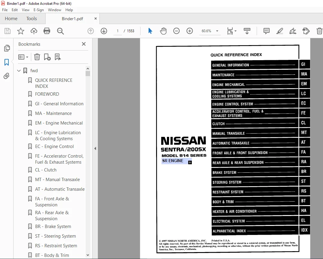
1998 NISSAN SENTRA 200SX B14 Series (SR Engine) Service Manual PDF DOWNLOAD
$24.95
1998 NISSAN SENTRA 200SX B14 Series (SR Engine) Service Manual PDF DOWNLOAD
Instant PDF Download
Available immediately
Save to Your Device
Download & keep forever
Antivirus Scanned
100% virus-free
Trusted Worldwide
175,000+ customers
Description
1998 NISSAN SENTRA 200SX B14 Series (SR Engine) Service Manual PDF DOWNLOAD
FILE DETAILS:
1998 NISSAN SENTRA 200SX B14 Series (SR Engine) Service Manual PDF DOWNLOAD
Language : English
Pages : 1553
Downloadable : Yes
File Type : PDF
IMAGES PREVIEW OF THE MANUAL:
VIDEO PRVIEW:
https://vimeo.com/853252954?share=copy
TABLE OF CONTENTS:
1998 NISSAN SENTRA 200SX B14 Series (SR Engine) Service Manual PDF DOWNLOAD
fwd 1
QUICK REFERENCE INDEX 1
FOREWORD 2
GI – General Information 0
MA – Maintenance 0
EM – Engine Mechanical 0
LC – Engine Lubrication & Cooling Systems 0
EC – Engine Control 0
FE – Accelerator Control, Fuel & Exhaust Systems 0
CL – Clutch 0
MT – Manual Transaxle 0
AT – Automatic Transaxle 0
FA – Front Axle & Suspension 0
RA – Rear Axle & Suspension 0
BR – Brake System 0
ST – Steering System 0
RS – Restraint System 0
BT – Body & Trim 0
HA – Heat & Air Conditioner 0
EL – Electrical System 0
IDX – Alphabetical Index 1
Foldout 0
Comment Sheet 3
Quick Reference Chart 4
GST Mode 6 – Test Value & Test Limit Chart 5
at 6
QUICK REFERENCE INDEX 0
TABLE OF CONTENTS 6
DIAGNOSTIC TROUBLE CODE INDEX 8
Alphabetical & P No Index for DTC 8
PRECAUTIONS AND PREPARATION 9
Precautions For Supplemental Restraint System (SRS) “AIR BAG” 9
Precautions 10
Service Notice or Precautions 11
Special Service Tools 13
Commercial Service Tools 16
OVERALL SYSTEM 17
Circuit Diagram for Quick Pinpoint Check 18
Wiring Diagram – AT- 19
Cross-sectional View 25
Hydraulic Control Circuit 26
Shift Mechanism 27
Control System 36
Control Mechanism 38
Control Valve 43
ON BOARD DIAGNOSTIC SYSTEM DESCRIPTION 44
Introduction 44
OBD-II Function for A/T System 44
One or Two Trip Detection Logic of OBD-ll 44
OBD-ll Diagnostic Trouble Code (DTC) 44
Malfunction Indicator Lamp (MIL) 48
CONSULT 48
Diagnostic Procedure without CONSULT 55
TROUBLE DIAGNOSIS- Introduction 59
Introduction 59
Diagnosis Worksheet 60
Work Flow 63
TROUBLE DIAGNOSIS – Basic Inspection 64
A/T Fluid Check 64
Stall Test 64
Line Pressure Test 67
Road Test 68
TROUBLE DIAGNOSIS – General Description 79
Symptom Chart 79
TCM Terminals and Reference Value 82
TROUBLE DIAGNOSIS FOR POWER SUPPLY 86
Main Power Supply and Ground Circuit 86
DTC P0705, Inhibitor Switch 87
DTC P0710, A/T Fluid Temperature Sensor 91
DTC P0720, Vehicle Speed Sensor A/T (Revolution sensor) 95
DTC P0725, Engine Speed Signal 99
DTC P0731, A/T 1st Gear Function 102
DTC P0732, A/T 2nd Gear Function 108
DTC P0733, A/T 3rd Gear Function 113
DTC P0734, A/T 4th Gear Function 118
DTC P0740, Torque Converter Clutch Solenoid Valve 126
DTC P0744, A/T TCC S/V Function (Lock-up) 130
DTC P0745, Line Pressure Solenoid Valve 137
DTC P0750, Shift Solenoid Valve A 141
DTC P0755, Shift Solenoid Valve B 145
DTC P1705, Throttle Position Sensor 149
DTC P1760, Overrun Clutch Solenoid Valve 156
TROUBLE DIAGNOSIS FOR BATT/FLUID TEM SEN 160
A/T Fluid Temperature Sensor Circuit and TCM Power Source 6
TROUBLE DIAGNOSIS FOR VHCL SPEED SEN-MTR 164
Vehicle Speed Sensor-MTR 164
TROUBLE DIAGNOSIS FOR SYMPTOMS 167
1 O/D OFF Indicator Lamp Does Not Come On 167
2 Engine Cannot Be Started In “P” and “N” Position 168
3 In “P” Position, Vehicle Moves Forward or Backward When Pushed 168
4 In “N” Position, Vehicle Moves 169
5 Large Shock “N” – “R” Position 170
6 Vehicle Does Not Creep Backward In “R” Position 171
7 Vehicle Does Not Creep Forward In “D”, “2” or “1” Position 172
8 Vehicle Cannot Be Started From D1 173
9 A/T Does Not Shift: D1 – D2 or Does Not Kickdown: D4 – D2 174
10 A/T Does Not Shift: D2 – D3 175
11 A/T Does Not Shift: D3 – D4 176
12 A/T Does Not Perform Lock-up 177
13 A/T Does Not Hold Lock-up Condition 178
14 Lock-up Is Not Released 178
15 Engine Speed Does Not Return To Idle (Light Braking D4 – D3) 179
16 Vehicle Does Not Start from D1 180
17 A/T Does Not Shift: D4 – D3, When Overdrive Control Switch “ON” – “OFF” 180
18 A/T Does Not Shift: D3 – 2,2 – 1,1 When Selector Lever “2” – “1” Position 181
19 A/T Does Not Shift: 2,2 – 1,1 When Selector Lever “2” – “1” Position 181
20 Vehicle Does Not Decelerate By Engine Brake 182
21 TCM Self-diagnosis Does Not Activate (Inhibitor, Overdrive Control and Throttle Position Switch Circuit Checks 182
TROUBLE DIAGNOSES – A/T Shift Lock System 188
Shift Lock System Electrical Parts Location 188
Wiring Diagram – SHIFT 189
Diagnostic Procedure 190
Key Interlock Cable 192
Component Check 194
ON-VEHICLE SERVICE 195
Control Valve Assembly and Accumulator 195
Control Cable Adjustment 196
Inhibitor Switch Adjustment 196
Differential Side Oil Seal Replacement 197
Revolution Sensor Replacement 197
REMOVAL AND INSTALLATION 198
MAJOR OVERHAUL 201
Locations of Adjusting Shims, Needle Bearings,Thrust Washers and Snap Rings 201
Oil Channel 202
DISASSEMBLY 206
REPAIR FOR COMPONENT PARTS 220
Manual Shaft 220
Oil Pump 223
Control Valve Assembly 227
Control Valve Upper Body 236
Control Valve Lower Body 240
Reverse Clutch 242
High Clutch 246
Forward Clutch and Overrun Clutch 251
Low & Reverse Brake 257
Rear Internal Gear, Forward Clutch Hub and Overrun Clutch Hub 261
Output Shaft, Idler Gear, Reduction Pinion Gear and Bearing Retainer 265
Band Servo Piston Assembly 270
Final Drive 275
ASSEMBLY 279
Assembly 1 279
Adjustment 1 280
Assembly 2 285
Adjustment 2 289
Assembly 3 293
Assembly 4 295
SERVICE DATA AND SPECIFICATIONS (SDS) 300
General Specifications 300
Specifications and Adjustments 300
br 307
QUICK REFERENCE INDEX 0
TABLE OF CONTENTS 307
PRECAUTIONS AND PREPARATION 309
Supplemental Restraint System (SRS) “AIR BAG” 309
Precautions for Brake System 309
Commercial Service Tools 309
NOISE, VIBRATION AND HARSHNESS (NVH) TROUBLESHOOTING 310
NVH Troubleshooting Chart 310
CHECK AND ADJUSTMENT 311
Checking Brake Fluid Level 311
Checking Brake Line 311
Checking Brake Fluid 311
AIR BLEEDING 312
Bleeding Procedure 312
BRAKE HYDRAULIC LINE 313
CONTROL VALVE 315
Proportioning Valve 315
BRAKE PEDAL AND BRACKET 317
Removal and Installation 317
Inspection 317
Adjustment 317
MASTER CYLINDER 319
Removal 319
Disassembly 319
Inspection 320
Assembly 320
Installation 321
BRAKE BOOSTER 322
On-vehicle Service 322
Removal 322
Inspection 322
Installation 323
VACUUM HOSE 324
Removal and Installation 324
Inspection 324
FRONT DISC BRAKE 325
Pad Replacement 325
Components 326
Removal 327
Disassembly 327
Inspection – Caliper 327
Inspection – Rotor 328
Assembly 328
Installation 328
Brake Burnishing Procedure 329
REAR DISC BRAKE 330
Pad Replacement 330
Components 332
Removal 333
Disassembly 333
Inspection – Caliper 334
Inspection – Rotor 335
Assembly 335
Installation 337
PARKING BRAKE CONTROL 338
Removal and Installation 338
Inspection 338
Adjustment 339
ANTI-LOCK BRAKE SYSTEM 340
Purpose 340
Operation 340
ABS Hydraulic Circuit 340
System Components 341
System Description 341
Removal and Installation 343
TROUBLE DIAGNOSES 347
How to Perform Trouble Diagnoses for Quick and Accurate Repair 347
Preliminary Check 348
Component Parts and Harness Connector Location 349
Schematic 350
Wiring Diagram -ABS- 351
Self-diagnosis 355
CONSULT 358
CONSULT Inspection Procedure 359
Ground Circuit Check 364
TROUBLE DIAGNOSES FOR SELF-DIAGNOSTIC ITEM 365
Diagnostic Procedure 1 (ABS Actuator Solenoid Valve) 365
Diagnostic Procedure 2 (Wheel Sensor or Rotor) 367
Diagnostic Procedure 3 (Motor Relay or Motor) 369
Diagnostic Procedure 4 (Solenoid Valve Relay) 372
Diagnostic Procedure 5 (Low Voltage) 375
Diagnostic Procedure 6 (Control Unit) 375
TROUBLE DIAGNOSES FOR SYMPTOM 376
Diagnostic Procedure 7 (Warning Lamp Does Not Come On) 376
Diagnostic Procedure 8 (Warning Lamp Stays On) 378
Diagnostic Procedure 9 (Pedal Vibration and Noise) 381
Diagnostic Procedure 10 (Long Stopping Distance) 382
Diagnostic Procedure 11 (Unexpected Pedal Action) 382
Diagnostic Procedure 12 (ABS Does Not Work) 383
Diagnostic Procedure 13 (ABS Works Frequently) 383
SERVICE DATA AND SPECIFICATIONS (SDS) 384
General Specifications 384
Inspection and Adjustment 385
bt 386
QUICK REFERENCE INDEX 0
TABLE OF CONTENTS 386
PRECAUTIONS AND PREPARATION 387
Precautions 387
Supplemental Restraint System (SRS) “AIR BAG” 387
Clip and Fastener 387
BODY END 390
Body Front End 390
Sedan 390
Removal – Front bumper assembly 390
Coupe 390
Removal – Front bumper assembly 390
Sedan 391
Coupe 392
Body Rear End and Opener 393
DOOR 395
Front Door 395
Rear Door 397
INSTRUMENT PANEL 398
INTERIOR TRIM 401
Side and Floor Trim 401
Door Trim 404
Roof Trim 406
Trunk Room Trim 407
EXTERIOR 408
(1) Hood front seal 408
(2) (3) Cowl top seal and cowl top grille 408
(4) Windshield side molding 408
(5) Windshield upper molding 409
(6) Drip weatherstrip 409
(7) Body side welt 409
(8) Door weatherstrip 409
(9) Rear window upper molding and side molding 409
(10) Rear window lower molding 409
(11) Door sash molding 410
(12) Rear door parting seal 410
(13) Rear door corner molding 410
(14) Door outside molding 410
(15) Sunroof lid weatherstrip 411
(16) Side ruard molding 411
(17) Trunk lid weatherstrip 411
(18) Trunk lid finisher 411
(19) Rear combination lamp 412
(20) Fender and center mudguard 413
(21) Rear air spoiler and high-mounted stop lamp 414
SEAT 415
Front Seat 415
Rear Seat 416
SUNROOF 417
Removal 418
Trouble Diagnoses 419
Drain Hoses 420
Weatherstrip 420
Link and Wire Assembly 420
Adjustment 421
WINDSHIELD AND WINDOWS 422
Windshield and Rear Window 423
Quarter Window 424
Coupe 424
Sedan 425
MIRROR 426
Door Mirror 426
BODY ALIGNMENT 427
Engine Compartment 427
Underbody 429
cl 431
QUICK REFERENCE INDEX 0
TABLE OF CONTENTS 431
PRECAUTIONS AND PREPARATION 432
Precaution 432
Special Service Tools 432
NOISE, VIBRATION AND HARSHNESS (NVH) TROUBLESHOOTING 433
NVH Troubleshooting Chart 433
CLUTCH SYSTEM 434
INSPECTION ADJUSTMENT 435
Adjusting Clutch Pedal 435
CLUTCH RELEASE MECHANISM 436
CLUTCH DISC AND CLUTCH COVER 437
Clutch Disc 437
Clutch Cover and Flywheel 438
SERVICE DATA AND SPECIFICATIONS (SDS) 439
General Specifications 439
Inspection and Adjustment 439
ec 440
QUICK REFERENCE INDEX 0
TABLE OF CONTENTS 440
DIAGNOSTIC TROUBLE CODE INDEX 443
Alphabetical & P No Index for DTC 443
PRECAUTIONS AND PREPARATION 445
Special Service Tools 445
Commercial Service Tools 445
Supplemental Restraint System (SRS) “AIR BAG” 446
Precautions for On Board Diagnostic (OBD) 446
System of Engine and A/T 446
Engine Fuel & Emission Control System 447
Precautions 448
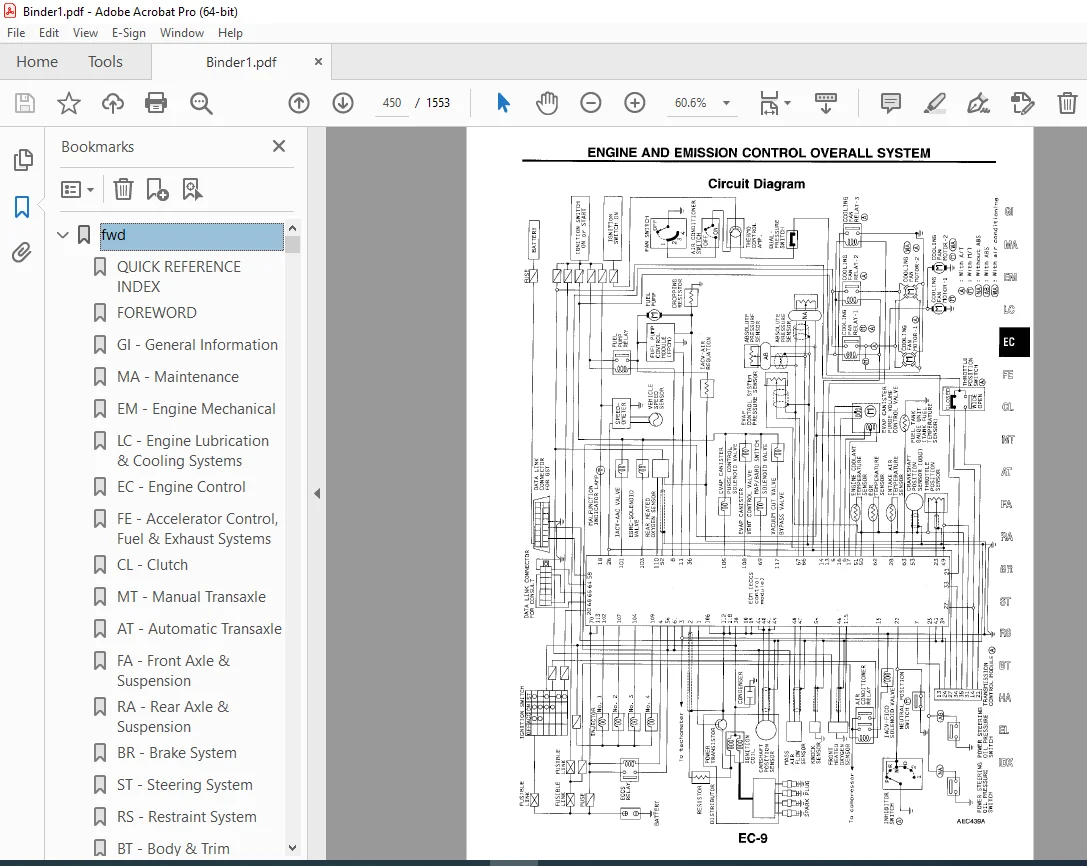
ENGINE AND EMISSION CONTROL OVERALL SYSTEM 458
Circuit Diagram 450
System Diagram 451
ECCS Component Parts Location 452
Vacuum Hose Drawing 456
System Chart 457
ENGINE AND EMISSION BASIC CONTROL SYSTEM DESCRIPTION 458
Multiport Fuel Injection (MFI) System 458
Distributor Ignition (DI) System 460
Air Conditioning Cut Control 461
Fuel Cut Control 462
EVAPORATIVE EMISSION SYSTEM 463
Description 463
Inspection 463
Evaporative Emission Line Drawing 466
On Board Refueling Vapor Recovery (ORVR) 468
POSITIVE CRANKCASE VENTILATION 473
Description 473
Inspection 473
BASIC SERVICE PROCEDURE 474
Fuel Pressure Release 474
Fuel Pressure Check 474
Fuel Pressure Regulator Check 475
Injector Removal and Installation 475
Idle Speed/Ignition Timing Mixture Ratio Adjustment 476
ON BOARD DIAGNOSTIC SYSTEM DESCRIPTION 483
Introduction 483
Two Trip Detection Logic 483
Emission-related Diagnostic Information 484
Malfunction Indicator Lamp (MIL) 495
OBD System Operation Chart 498
CONSULT 503
Generic Scan Tool (GST) 517
TROUBLE DIAGNOSIS – Introduction 519
Introduction 519
Diagnostic Worksheet 519
TROUBLE DIAGNOSIS – Work Flow 521
Work Flow 521
Description for Work Flow 522
TROUBLE DIAGNOSIS – Basic Inspeciton 523
Basic Inspeciton 523
TROUBLE DIAGNOSIS – General Description 528
Diagnostic Trouble Code (DTC) Inspection Priority Chart 528
Priority Chart 528
Fail-Safe Chart 529
Symptom Matrix Chart 530
CONSULT Reference Value in Data Monitor Mode 533
Major Sensor Reference Graph in Data Monitor Mode 536
ECM Terminals and Reference Value 538
TROUBLE DIAGNOSIS FOR INTERMITTENT INCIDENT 547
Description 547
Common l/l Report Situations 547
Diagnostic Procedure 547
TROUBLE DIAGNOSIS FOR POWER SUPPLY 548
Main Power Supply and Ground Circuit 548
DTC P0100, Mass Air Flow Sensor (MAFS) 553
DTC P0105, Absolute Pressure Sensor 562
DTC P0110, Intake Air Temperature Sensor 570
DTC P0115, Engine Coolant Temperature Sensor (ECTS) (Circurit) 576
DTC P0120, Throttle Position Sensor 581
DTC P0125, Engine Coolant Temperature (ECT) Sensor 593
DTC P0130, Front Heated Oxygen Sensor (Circuit) (Front HO2S) 598
DTC P0131, Front Heated Oxygen Sensor (Lean Shift Monitoring) (Front HO2S) 604
DTC P0132, Front Heated Oxygen Sensor (Rich Shift Moniorint) (Front H02S) 610
DTC P0133, Front Heated Oxygen Sensor (Response Monitoring) (Front H02S) 616
DTC P0134, Front Heated Oxygen Sensor (High Voltage) (Front H02S) 624
DTC P0135, Front Heated Oxygen Sensor Heater 629
DTC P0137, Rear Heated Oxygen Sensor (Min Voltage Monitoring) (Rear H02S) 633
DTC P0138, Rear Heated Oxygen Sensor (Max Voltage Monitoring) (Rear H02S) 640
DTC P0139, Rear Heated Oxygen Sensor (Response Moitoring) (Rear H02S) 647
DTC P0140, Rear Heated Oxygen Sensor (High Voltage) (Rear H02S) 653
DTC P0141, Rear Heated Oxygen Sensor Heater 658
DTC P0171, Fuel Injection System Function (Lean side) 662
DTC P0172, Fuel Injection System Function (Rich side) 668
DTC P0180, Tank Fuel Temperature Sensor 673
DTC P0300-P0304, No 4-1 Cylinder Misfire, Multiple Cylinder Misfire 677
DTC P0325, Knock Sensor (KS) 682
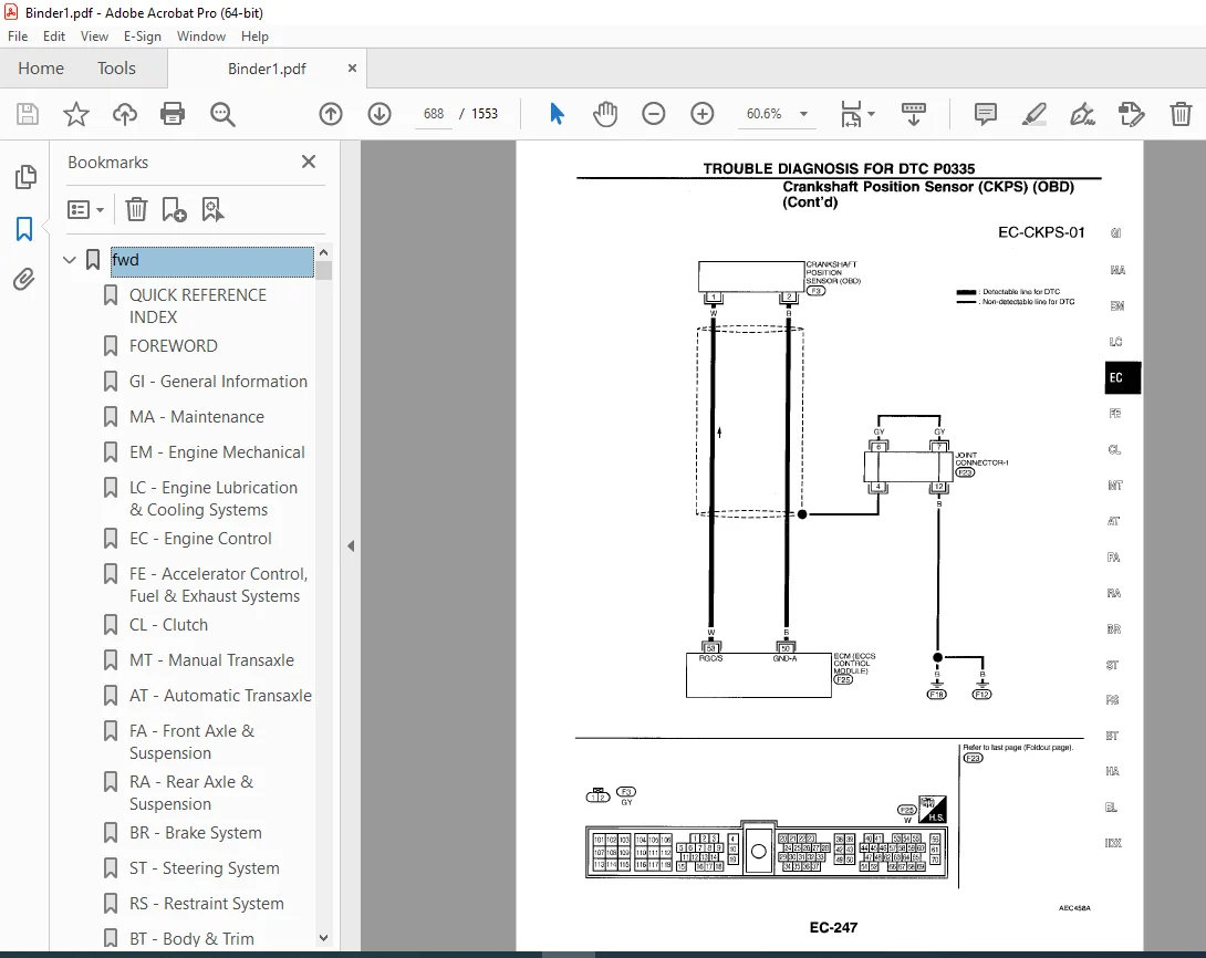
DTC P0335, Crankshaft Position Sensor (CKPS) (OBD) 686
DTC P0340, Camshaft Position Sensor (CMPS) 691
DTC P0400, EGR Function (Close) 697
DTC P0402, EGRC-BPT Valve Function 706
DTC P0420, Three Way Catalyst Function 711
DTC P0440, Evaporate Emission (EVAP) Control System (Small Leak) (Negative Pressure) 715
DTC P0443, Evaporate Emission (EVAP) Canister Purge Volume Control Valve 726
DTC P0446, Evaporate Emission (EVAP) Control System Pressure Sensor 732
DTC P0450, Evaporative Emission (EVAP) Control System Pressure Sensor 737
DTC P0500, Vehicle Speed Sensor (VSS) 743
DTC P0505, Idle Air Control Valve (IACV) – Auxiliary Air Control (AAC) Valve 747
DTC P0510, Closed Throttle Postion Switch 752
DTC P0605, Engine Control Module (ECM) 757
DTC P1105, Manifold Absolute Pressure (MAP)/ Barometric Pressure (BARO) Switch Solenoid Valve 759
DTC P1148, Closed Loop Control 767
DTC P1220, Fuel Pump Control Module (FPCM) 769
DTC P1320, Ignition Signal 776
DTC P1336, Crankshift Position Sensor (CKPS) (OBD) (COG) 783
DTC P1400, EGRC- Solenoid Valve 788
DTC P1401, EGR Temperature Sensor 793
DTC P1402, EGR FUNCTION (Open) 799
DTC P1440, Evaporate Emission (EVAP) Control System (Small Leak) (Positive Pressure) 806
DTC P1444, Evaporate Emission (EVAP) Control System (Small Leak) (Positive Pressure) 817
DTC P1446, Evaporate Emission (EVAP) Canister Vent Control Valve (Close) 826
DTC P1447, Evaporate Emission (EVAP) Control System Purge Flow Moitoring 831
DTC P1448, Evaporate Emission (EVAP) Canister Vent Control Valve (Open) 840
DTC P1490, Vacuum Cut Valve Bypass Valve (Circuit) 846
DTC P1491, Vacuum Cut Valve Bypass Valve 851
DTC P1492, Evaporative Emission (EVAP) Canister Purge Conrol valve/Solenoid Valve (Circuit) 857
DTC P1493, Evaporative Emission (EVAP) Canister Purge Control Valve/Solenoid Valve 863
DTC P1605, A/T Diagnosis Communication Line 871
DTC P1706, Park/Neutral Position Switch 874
TROUBLE DIAGNOSIS FOR OVERHEAT 879
Overheat 879
TROUBLE DIAGNOSIS FOR NON-DETECTABLE ITEMS 893
Injector 893
Start Signal 896
Fuel Pump 899
Power Steering Oil Pressure Switch 903
IACV-Air Regulator 907
IACV-FICD Solenoid Valve 911
MIL & Data Link Connectors 915
SERVICE DATA AND SPECIFICATIONS (SDS) 916
General Specifications 916
Inspection and Adjustment 916
el 918
QUICK REFERENCE INDEX 0
TABLE OF CONTENTS 918
PRECAUTIONS AND PREPARATION 921
Supplemental Restraint System (SRS) “AIR BAG” 921
HARNESS CONNECTOR 922
STANDARD RELAY 923
POWER SUPPLY ROUTING 925
Schematic 925
Wiring Diagram – POWER – 927
Fuse 933
Fusible Link 933
Circuit Breaker Inspection 933
GROUND DISTRIBUTION 934
BATTERY 937
How to Handle Battery 937
Service Data and Specifications (SDS) 940
STARTING SYSTEM 942
System Description 942
Wiring Diagram – START – 944
Construction 947
Pinion/Clutch Check 949
Service Data and Specifications (SDS) 949
CHARGING SYSTEM 950
System Description 950
Wiring Diagram – CHARGE – 951
Trouble Diagnoses 952
Construction 953
Diode Check 954
Disassembly and Assembly 955
Service Data and Specifications (SDS) 956
COMBINATION SWITCH 957
Check 957
Replacement 958
STEERING SWITCH 959
Check 959
HEADLAMP 960
System Description (For USA) 960
Wiring Diagram – H/LAMP – 961
Trouble Diagnoses (For USA) 962
Bulb Replacement 963
Aiming Adjustment 963
HEADLAMP – Daytime Light System – 964
System Description (For Canada) 964
Operation (For Canada) 965
Schematic (For Canada) 966
Wiring Diagram (For Canada) – DTRL – 967
Trouble Diagnoses (For Canada) 970
Bulb Replacement 971
Aiming Adjustment 971
BACK-UP LAMP 972
Wiring Diagram – BACK/L- 972
LICENSE, TAIL AND STOP LAMPS 973
Wiring Diagram – TAIL/L – 973
FRONT FOG LAMP 975
System Description 975
Wiring Diagram – F/FOG – 976
Aiming Adjustment 977
TURN SIGNAL AND HAZARD WARNING LAMPS 979
System Description 979
Wiring Diagram – TURN – 981
Trouble Diagnosis 983
Electrical Component Inspection 983
ILLUMINATION 984
System Description 984
Wiring Diagram – ILL – 985
INTERIOR AND TRUNK ROOM LAMPS 987
System Description 987
Wiring Diagram – INT/L – 989
Trouble Diagnoses 991
METERS AND GUAGES 992
System Description 992
Combination Meter 993
Wiring Diagram – METER – 994
Trouble Diagnoses 995
WARNING LAMPS 1001
System Description 1001
Schematic 1003
Wiring Diagram – WARN – 1004
Electrical Component Inspection 1007
WARNING CHIME 1009
System Description 1009
Wiring Diagram – CHIME – 1010
Trouble Diagnoses 1011
Electrical Component Inspection 1014
WIPER AND WASHER 1015
System Description 1015
Wiring Diagram – WIPER – 1017
Trouble Diagnoses 1020
Wiper Installation and Adjustment 1022
Washer Nozzle Adjustment 1023
HORN 1024
Wiring Diagram – CIGAR – 1024
CIGARETTE LIGHTER 1025
Wiring Diagram -CIGAR- 1025
REAR WINDOW DEFOGGER 1026
System Description 1026
Wiring Diagram – DEF – 1027
Trouble Diagnoses 1028
Filament Check 1029
Filament Repair 1030
AUDIO 1032
System Description 1032
Wiring diagram – AUDIO – 1033
Trouble Diagnoses 1034
Inspection 1035
ELECTRIC SUNROOF 1036
Wiring Diagram – SROOF – 1036
DOOR MIRROR 1037
Wiring Diagram – MIRROR – 1037
AUTOMATIC SPEED CONTROL DEVICE (ASCD) 1039
Component Parts and Harness Connector Location 1039
System Description 1040
Schematic 1042
Wiring Diagram – ASCD – 1043
Fail-safe System Description 1049
Fail-Safe System Check 1050
Trouble Diagnoses 1051
ASCD Wire Adjustment 1059
Electrical Component Inspection 1060
POWER WINDOW 1062
System Description 1062
Wiring Diagram – WINDOW – 1065
Trouble Diagnoses 1067
POWER DOOR LOCK 1068
System Description 1068
Schematic 1070
Wiring Diagram – D/LOCK – 1071
Trouble Diagnoses 1075
MULTI-REMOTE CONTROL SYSTEM 1084
System Description 1084
Schematic 1086
Wiring Diagram – MULTI – 1087
Trouble Diagnoses 1091
ID Code Entry Procedure 1097
THEFT WARNING SYSTEM 1098
Component Parts and Harness Connector Location 1098
System Description 1099
Schematic 1102
Wiring Diagram – THEFT – 1103
Trouble Diagnoses 1109
SMART ENTRANCE CONTROL UNIT 1123
Description 1123
Input/Output Operation Signal 1124
LOCATION OF ELECTRICAL UNITS 1125
Engine Compartment 1125
Passenger Compartment 1126
Outline 1127
HARNESS LAYOUT 1128
How To Read Harness Layout 1128
Main Harness 1129
Engine Room Harness 1131
Engine Control Harness 1135
Engine Harness No 2 and Generator Harness 1136
Body Harness 1137
Body Harness No 2 1139
Room Lamp Harness 1140
Air Bag Harness 1141
Tail Harness 1142
Front Door Harness (2-Door) 1143
Front Door Harness (4-Door) 1144
Rear Door Harness (4-Door) 1145
BULB SPECIFICATIONS 1146
WIRING DIAGRAM CODES (CELL CODES) 1147
Wiring Diagram Codes (Cell Codes) 1147
em 1148
QUICK REFERENCE INDEX 0
TABLE OF CONTENTS 1148
PRECAUTIONS 1149
Parts Requiring Angular Tigtening 1149
Liquid Gasket Application Procedure 1149
PREPARATION 1150
Special Service Tools 1150
Commercial Service Tools 1153
NOISE, VIBRATION AND HARSHNESS (NVH) TROUBLESHOOTING 1154
NVH Troubleshooting – Engine Noise 1155
OUTER COMPONENT PARTS 1156
OIL PAN 1160
Removal 1160
Installation 1163
TIMING CHAIN 1165
Removal 1166
Inspection 1170
Installation 1170
OIL SEAL REPLACEMENT 1180
Valve Oil Seal 1180
Front Oil Seal 1180
Rear Oil Seal 1181
CYLINDER HEAD 1182
Removal 1183
Disassembly 1183
Inspection 1186
Cylinder Head Distortion 1186
Camshaft Visual Check 1186
Camshaft Runout 1186
Camshaft Cam Height 1186
Camshaft Journal Clearance 1187
Camshaft End Play 1187
Camshaft Sprocket Runout 1188
Valve Guide Clearance 1188
Valve Guide Replacement 1188
Valve Seats 1189
Replacing Valve Seat For Service Parts 1190
Valve Dimensions 1190
Valve Spring 1191
Hydraulic Lash Adjuster 1191
Rocker Arm, Shim And Rocker Arm Guide 1192
Assembly 1192
Installation 1195
ENGINE REMOVAL 1196
Removal 1197
Installation 1199
CYLINDER BLOCK 1200
Disassembly 1201
Inspection 1201
Piston And Piston Pin Clearance 1201
Piston Ring Side Clearance 1202
Piston Ring End Gap 1202
Connecting Rod Bend And Torsion 1202
Cylinder Block Distortion And Wear 1203
Piston- To- Bore Clearance 1203
Crankshaft 1204
Bearing Clearance 1205
Connecting Rod Bushing Clearance (Small end) 1207
Replacement of Pilot Bushing (M/T) Or Pilot Converter (A/T) 1208
Flywheel/Drive Plate Runout 1208
Assembly 1209
SERVICE DATA AND SPECIFICATIONS (SDS) 1212
General Specifications 1212
Inspection and Adjustment 1212
fa 1220
QUICK REFERENCE INDEX 0
TABLE OF CONTENTS 1220
PRECAUTIONS AND PREPARATION 1221
Precautions 1221
Special Service Tools 1221
Commercial Service Tools 1222
NOISE, VIBRATION AND HARSHNESS (NVH) TROUBLESHOOTING 1223
NVH Troubleshooting Chart 1223
FRONT AXLE AND FRONT SUSPENSION 1224
Components 1224
ON-VEHICLE SERVICE 1225
Front Axle and Front Suspension Parts 1225
Front Wheel Bearing 1226
Front Wheel Alignment 1226
Drive Shaft 1227
FRONT AXLE 1228
Wheel Hub and Knuckle 1228
Removal 1228
Installation 1230
Disassembly 1230
Inspection 1231
Assembly 1231
Drive Shaft 1233
Removal 1233
Installation 1234
Components 1234
Disassembly 1236
Inspection 1237
Assembly 1238
FRONT SUSPENSION 1242
Components 1242
Coil Spring and Struct Assembly 1243
Removal and Installation 1243
Disassembly 1243
Inspection 1243
Assembly 1244
Stabilizer Bar 1244
Removal and Installation 1244
Inspection 1245
Transverse Link and Lower Ball joint 1245
Removal And Installation 1245
Inspection 1246
SERVICE DATA AND SPECIFICATIONS (SDS) 1247
General Specifications 1247
Inspection and Adjustment 1248
fe 1249
QUICK REFERENCE INDEX 0
TABLE OF CONTENTS 1249
ACCELERATOR CONTROL SYSTEM 1250
Accelerator Control System 1250
Adjusting Accelerator Wire 1250
FUEL SYSTEM 1251
Fuel Tank 1251
FUEL SYSTEM 1253
Fuel Pump and Gauge 1253
Removal 1253
Installation 1253
EXHAUST SYSTEM 1254
foldout 1255
QUICK REFERENCE INDEX 0
SUPER MULTIPLE JUNCTION (SMJ) 1255
INSTALLATION 1255
Terminal Arrangement 1256
FUSE BLOCK – JUNCTION BOX (J/B) 1257
Terminal Arrangement 1257
FUSE AND FUSIBLE LINK BOX 1258
Terminal Arrangement 1258
ELECTRICAL UNITS 1259
Terminal Arrangement 1259
JOINT CONNECTOR (J/C) 1260
Terminal Arrangement 1260
gi 1261
QUICK REFERENCE INDEX 0
TABLE OF CONTENTS 1261
PRECAUTIONS AND PREPARATION 1262
Supplemental Restraint System (SRS) “AIR BAG” 1262
General Precautions 1263
Precautions for Multiport Fuel Injection System or ECCS Engine 1265
Precautions for Three Way Catalyst 1265
Precautions for Engine Oils 1265
Precautions for Fuel 1266
Precautions for Air Conditioning 1266
HOW TO USE THIS MANAUL 1267
HOW TO READ WIRING DIAGRAMS 1269
Sample/Wiring Diagram – EXAMPL- 1269
Description 1271
HOW TO CHECK TERMINAL 1277
Connector and Terminal Pin Kit 1277
How to Probe Connectors 1277
How to Check Enlarged Contact Spring of Terminal 1278
Waterproof Connector Inspection 1279
Terminal Lock Inspection 1279
HOW TO PERFORM EFFICIENT DIAGNOSES FOR AN ELECTRICAL INCIDENT 1280
Work Flow 1280
Incident Simulation Tests 1281
Circuit Inspection 1283
HOW TO FOLLOW FLOW CHART IN TROUBLE DIAGNOSES 1290
How To Follow This Flow Chart 1291
CONSULT CHECKING SYSTEM 1293
Function and System Application 1293
Lithium Battery Replacement 1293
Checking Equipment 1293
Loading Procedure 1294
CONSULT Data Link Connector (DLC) Circuit 1294
IDENTIFICATION IFORMATION 1295
Model Variation 1295
Identification Number 1296
Dimensions 1298
Wheels and Tires 1298
LIFTING POINTS AND TOW TRUCK TOWING 1299
Preparation 1299
Board-on Lift 1300
Garage Jack and Safety Stand 1300
2-pole Lift 1301
Tow Truck Towing 1301
TIGHTENING TORQUE OF STANDARD BOLTS 1303
SAE J1930 TERMINOLOGY LIST 1304
ha 1308
QUICK REFERENCE INDEX 0
TABLE OF CONTENTS 1308
PRECAUTIONS AND PREPARATION 1309
Supplemental Restraint System (SRS) “AIR BAG” 1309
Precautions for Working With HFC-134a (R-134a) 1309
Precautions for Working with Refrigerants 1310
Precautions for Refrigerant Connection 1311
Precautions for Servicing Compressor 1314
Special Service Tools 1315
R-134a Service Tools and Equipment 1316
Precautions for Service Equipment 1318
DESCRIPTION 1320
Refrigeration Cycle 1320
Component Layout 1321
Control Operation 1322
Discharge Air Flow 1323
Harness Layout 1324
Circuit Diagram – Air Conditioner 1326
Wiring Diagram – HEATER – 1327
Wiring Diagram – A/C – 1328
TROUBLE DIAGNOSES 1331
How to Perform Trouble Diagnoses for Quick and Accurate Repair 1331
Operational Check 1332
Blower Motor Circuit 1334
Air Outlet 1338
Air Mix Door 1340
Intake Door 1342
Magnet Clutch Circuit 1345
Trouble Diagnoses For Insufficient Cooling 1352
Performance Test Diagnoses 1353
Performance Chart 1355
Trouble Diagnoses for Abnormal Pressure 1356
Trouble Diagnoses for Insufficient Heating 1360
Trouble Diagnoses for Noise 1362
SERVICE PROCEDURES 1363
Refrigerant Lines 1363
Checking Refrigerant Leaks 1364
R-134a Service Procedure 1367
Compressor Lubricant Quantity 1369
Compressor Mounting 1371
Belt Tension 1371
Fast Idle Control Device (FICD) 1371
Compressor 1372
Compressor Clutch 1372
Thermal Protector 1374
Heater Unit (Heater Core) 1375
Cooling Unit 1376
Control Assembly 1377
SERVICE DATA AND SPECIFICATIONS (SDS) 1378
General Specifications 1378
Inspection and Adjustment 1378
idx 1379
QUICK REFERENCE INDEX 0
lc 1388
QUICK REFERENCE INDEX 0
TABLE OF CONTENTS 1388
PRECAUTIONS 1389
Liquid Gasket Application Procedure 1389
PREPARATION 1390
Special Service Tools 1390
ENGINE LUBRICATION SYSTEM 1391
Lubrication Circuit 1391
Oil Pressure Check 1391
Oil Pump 1392
Oil Filter 1394
ENGINE COOLING SYSTEM 1395
Cooling Circuit 1395
System Check 1395
Water Pump 1396
Thermostat 1398
Water Outlet 1399
Radiator 1400
Overheating Cause Analysis 1401
SERVICE DATA AND SPECIFICATIONS (SDS) 1402
Engine Lubrication System 1402
Engine Cooling System 1402
ma 1403
QUICK REFERENCE INDEX 0
Table of Contents 1403
PRECAUTIONS AND PREPARATION 1404
Supplemental Restraint System (SRS) “AIR BAG” 1404
Special Service Tools 1404
GENERAL MAINTENANCE 1405
PERIODIC MAINTENANCE 1407
Schedule 1 1408
Schedule 2 1409
RECOMMENDED FLUIDS AND LUBRICANTS 1410
Fluids and Lubricants 1410
SAE Viscosity Number 1410
Antifreeze Coolant Mixture Ratio 1411
ENGINE MAINTENANCE 1412
Checking Drive Belts 1412
Changing Engine Coolant 1413
Checking Fuel Lines 1415
Checking Fuel Filter 1415
Changing Air Cleaner Fiber 1416
Changing Engine Oil 1416
Changing Oil Filter 1417
Changing Spark Plugs (Platinum-tipped typed) 1417
Changing Spark Plugs (Conventional type) 1419
Checking EVAP Vapor Lines 1420
CHASSIS AND BODY MAINTENANCE 1421
Checking Exhaust System 1421
Checking Clutch System 1421
Checking M/T Oil 1421
Changing M/T Oil 1421
Checking A/T Fluid 1422
Changing A/T Fluid 1422
Checking Brake Fluid Level and Leaks 1423
Checking Brake Lines and Cables 1423
Checking Disc Brake 1423
Balancing Wheels 1425
Tire Rotation 1425
Checking Steering Gear and Linkage 1425
Checking Power Steering Fluid and Lines 1425
Lubricating Locks, Hinges and Hood Latches 1426
Checking Seat Belts, Buckles, Retractors, Anchors and Adjusters 1426
SERVICE DATA AND SPECIFICATIONS (SDS) 1427
Engine Maintenance 1427
Chassis and Body Maintenance 1427
mt 1428
QUICK REFERENCE INDEX 0
TABLE OF CONTENTS 1428
PREPARATION 1429
Special Service Tools 1429
Commercial Service Tools 1431
NOISE, VIBRATION AND HARSHNESS (NVH) TROUBLESHOOTING 1432
NVH Troubleshooting Chart 1432
ON-VEHICLE SERVICE 1433
Replacing Oil Seal 1433
Position Switch Check 1434
REMOVAL AND INSTALLATION 1435
TRANSAXLE GEAR CONTROL 1436
MAJOR OVERHAUL 1437
Case Components 1437
Gear Components 1438
Shift Control Components 1439
DISASSEMBLY 1440
REPAIR FOR COMPONENT PARTS 1443
Input Shaft and Gears 1443
Mainshaft and Gears 1446
Final Drive 1452
Shift Control Components 1454
Case Components 1456
ADJUSTMENT 1460
Differential Side Bearing Preload 1460
ASSEMBLY 1462
SERVICE DATA AND SPECIFICATIONS (SDS) 1466
General Specifications 1466
Inspection and Adjustment 1465
ra 1468
QUICK REFERENCE INDEX 0
TABLE OF CONTENTS 1468
PRECAUTIONS AND PREPARATION 1469
Precautions 1469
Special Service Tools 1469
Commercial Service Tools 1469
NOISE, VIBRATION AND HARSHNESS (NVH) TROUBLESHOOTING 1470
NVH Troubleshooting Chart 1470
ON-VEHICLE SERVICE 1471
Components 1471
Rear Axle and Rear Suspension Parts 1472
Rear Wheel Bearing 1472
Rear Wheel Alignment 1473
REAR AXLE 1474
Wheel Hub 1474
REAR SUSPENSION 1476
Components 1476
Removal 1477
Installation 1477
Coil Spring and Shock Absorber 1478
Removal 1478
Disassembly 1478
Inspection 1478
Assembly 1479
Torsion Beam, Lateral Link and Control Rod 1480
Disassembly 1480
Inspection 1480
Rubber Bushing Replacement 1480
Assembly 1481
SERVICE DATA AND SPECIFICATIONS (SDS) 1482
General Specifications 1482
Inspection and Adjustment 1482
rs 1483
QUICK REFERENCE INDEX 0
TABLE OF CONTENTS 1483
PRECAUTIONS AND PREPARATION 1484
Supplemental Restraint System (SRS) “AIR BAG” 1484
SEAT BELTS 1485
Front Seat Belt 1486
2-Door COUPE 1486
Removal 1487
4-Door SEDAN 1488
Removal 1489
Rear Seat Belt 1490
Removal 1491
2-door coupe 1491
4-door sedan 1491
Seat Belt Inspection 1492
SUPPLEMENTAL RESTRAINT SYSTEM (SRS) 1495
Precautions for SRS “Air Bag” Service 1495
Special Service Tools 1495
Description 1496
SRS Component Parts Location 1496
Maintenance Items 1497
Diagnosis Sensor Unit 1498
Removal And Installation 1498
Drive Air Bag Module and Spiral Cable 1499
Removal 1499
Installation 1500
Front Passenger Air Bag Module 1501
Removal 1501
Installation 1502
Disposal of Air Bag Module 1503
Checking Deployment Tool 1503
Deployment Procedures For Air Bag Module (Outside of Vehicle) 1504
Deployment of Air Bag Module While Mounted In Vehicle 1506
Disposing of Air Bag Module 1506
TROUBLE DIAGNOSES – Supplemental Restraint System (SRS) 1507
Trouble Diagnosis Introduction 1483
How to Perform Trouble Diagnoses for Quick and Accurate Repair 1510
Schematic 1511
Wiring Diagram – SRS – 1512
Self Diagnosis 1514
Trouble Diagnoses for Air Bag Warning Lamp 1527
COLLISION DIAGNOSIS 1529
st 1532
QUICK REFERENCE INDEX 0
TABLE OF CONTENTS 1532
PRECAUTIONS AND PREPARATION 1533
Supplemental Restraint System (SRS) “Air Bag” 1533
Precautions for Steering System 1533
Special Service Tools 1533
Commercial Service Tool 1534
NOISE, VIBRATION AND HARSHNESS (NVH) TROUBLESHOOTING 1535
NVH Troubleshooting Chart 1535
ON-VEHICLE SERVICE 1536
Checking and Adjusting Drive Belts 1536
Checking Fluid Level 1536
Checking Fluid Leakage 1536
Bleeding Hydraulic System 1537
Checking Steering Wheel Turning Force 1537
Checking Steering Wheel Play 1538
Checking Neutral Position on Steering Wheel 1538
Front Wheel Turning Angle 1538
Checking Gear Housing Movement 1538
Checking Hydraulic System 1539
STEERING WHEEL AND STEERING COLUMN 1540
Steering Wheel 1540
Steering Column 1541
POWER STEERING GEAR AND LINKAGE 1544
Removal and Installation 1544
Disassembly 1547
Inspection 1547
Assembly 1547
POWER STEERING PUMP 1549
Pre-disassembly Inspection 1549
Disassembly 1550
Inspection 1550
Assembly 1551
SERVICE DATA AND SPECIFICATIONS (SDS) 1552
General Specifications 1552
Inspection and Adjustment 1552
DESCRIPTION:
1998 NISSAN SENTRA 200SX B14 Series (SR Engine) Service Manual PDF DOWNLOAD
FOREWORD
- This manual contains maintenance and repair procedures for the 1998 Nissan SENTRA/200SX.
- In order to assure your safety and the efficient functioning of the vehicle, this manual should be read thoroughly.
- It is especially important that the PRECAUTIONS in the GI section be completely understood before starting any repair task.
- All information in this manual is based on the latest product information at the time of publication. The right is reserved to make changes in specifications and methods at any time without notice.
IMPORTANT SAFETY NOTICE
- The proper performance of service is essential for both the safety of the technician and the efficient functioning of the vehicle.
- The service methods in this Service Manual are described in such a manner that the service may be performed safely and accurately.
- Service varies with the procedures used, the skills of the technician and the tools and parts available.
- Accordingly, anyone using service procedures, tools or parts which are not specifically recommended by NISSAN must first be completely satisfied that neither personal safety nor the vehicle’s safety will be jeopardized by the service method selected.
PLEASE NOTE:
- This is the same manual used by the dealers to diagnose and troubleshoot your vehicle
- You will be directed to the download page as soon as the purchase is completed. The whole payment and downloading process will take anywhere between 2-5 minutes
- Need any other service / repair / parts manual, please feel free to contact [email protected] . We still have 50,000 manuals unlisted
G.P