1999 Doosan DH200 200LC Excavator Illustrated Parts Manual PDF
Original price was: $110.00.$31.95Current price is: $31.95.
1999 Doosan DH200 200LC Excavator Parts Manual – PDF DOWNLOAD
Parts Manual
2021-7019AL
Serial Number 001 and Up
February 1999
Daewoo
Description
1999 Doosan DH200 200LC Excavator Parts Manual – PDF DOWNLOAD
DESCRIPTION:
1999 Doosan DH200 200LC Excavator Parts Manual – PDF DOWNLOAD
- Daewoo reserves the right to improve our products in a continuing process to provide the best possible product to the market place. These improvements can be implemented at any time with no obligation to change materials on previously sold products.
- It is recommended that consumers periodically contact their distributors for recent documentation on purchased equipment. This documentation may include attachments and optional equipment that is not available in your machine’s package.
- Please call your distributor for additional items that you may require. Illustrations used throughout this manual are used only as a representation of the actual piece of equipment, and may vary from the actual item.
2. HOW TO USE THIS PARTS LIST
- Key No. : Key No. shows the referring number of illustration Parts No. : Parts No. consist of figures only.
- Description : Component parts of assembling parts are shown with r • J marks and shown below of assembling parts. Also, if the component parts marked r • J consist of further component parts, these further component parts are with r • • J. Q’ ty : Q’ ty shows the quantity used for one machine, however “Q’ ty” of component parts shows the Q’ ty used for one assembling parts. Serial No. :
- Serial No. shows the machine serial number which the parts were applied. Parts without any applicable serial number are used in every machine. Remarks : Parts numbers described in “Remarks” is our old part number being used for reference.
- When repairing, it is recommended to use our standard parts. Researching the assembling parts from parts No., see the “Parts Index” in the end of this parts list. DAEWOO HEAVY INDUSTRIES LTD
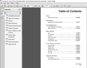
TABLE OF CONTENTS:
1999 Doosan DH200 200LC Excavator Parts Manual – PDF DOWNLOAD
Bloc cylindres ……………………………… 011-01
012 Timing Gear Case …………………………… Carter de distribution ……………………. 012-03
013 Fly \\heel Housing …………………………… Carter de volant moteur …………………. 013-04
014 Crank Shaft …………………………………… Vilebrequin ._. ……………………………….. 014-05
015 Piston …………………………………………… f>iston ………………………………………. · 015-06
016 q,linder Head …………………………………. Cullasse········ ………………………………. 016-07
017 Cam Shaft ……………………………………… Arbre a cames ……………………………. · 017-08
018 Intermediate Gear …………………………… f>ignon intermediaire, pome a huile ……… 018-09
019 Oil Pipe(ln Oil Pan) ………………………… Carterd’huile,conduite d’huile ……….. 019-10
Q20 Oil Filter ……………………………………… Filtre a huile ………………………………. 020-11
021 Oil Cooler …………………………………….. · Refroidissement de l’huile ………………. 021-12
022 Water Pump …………………………………… Pompe a eau. ventilateur …………………. 022-13
023 Water Chamber Cover ……………………… Circuit d’eau de refroidissement ………… 023-14
024 Intake Manifold ………………………………… Tubulures admission• echappoment ………. 024-15
025 Freheating System · · ·· · ·· ……. ·· · ·· · .. · .. · ·· · ·· · · Systeme de prechauffage …. · .. · …… ·· · ….. 025-16
026 Nozzle &Holder Ass ‘y ( DKC) ……………. Injecteur et porte •injecteur ……………… 026-17
027 Injection Pipe ·········· ……………………….. Alimentation et injection de gazole ……… 027-19
028 Injection Pump ········· ………………………… Pompe d’injection …………………………. 028-20
029 Fuel Filter (1) ……….. ; ……………………… Filtre a gazole (1) …………………………. 029-21
030 Fuel Filter (2} ………………………………… Filtre a gazzole (2) ………………………… 030-22
031 Generator (1) …………………………………… Alternateur (1) ……………………………… 031-23
032 Generator (2} …………………………………… Alternateur (2) ······ ……………………….. o32-24
033 Starter ······•······· ……………………………. I)emarreur ········ ………………………….. · 033-25
034 Air Compressor Mounting …………………. Support de compresseur d’air ……………. 034-26 –
SWING BODY PARTS TOURELLE
Fig.101 Frame ···•············· ……………………………. Chassis ……………………………………… 101-27
102 Engine Mounting ……………………………. Moteur········ ………………………………… 102-28
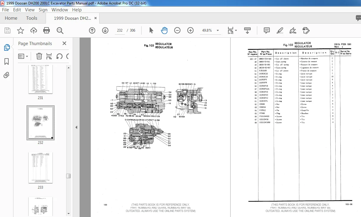
103 Radiator(!) ……. ; …………………………….. ·Rediateur (1) …………………………………. 103-30
104 Radiator (2} …………………………………… Radiateur (2) ………………………………… 104-31
105 Air Cleaner (1) ………………………………… Filtre a air …………………………………. 105-32
106 Air Cleaner (2) ………………………………… Filtre a air ··········· .. · ……………………… 106-33
107 Fuel Tank ……………………………………… Reservoir a gazole ………………………… 107-34
108 Oil Tank ……………………………………. : .. ···Reservoir a huile hydraulique …………… 108-35
109 Center Joint ……………………………………. Joint tournant …………………….. 109-36
110 Swing Device …………………………………… Systeme d’orientation···—-·· .. ·· ………….. 110-37
111 Oil Cooler Piping ……………………………… Canalisations refroidissement d’huile ·····111-38
112 Main Piping …………………………………… Circuit hydraulique principal ··········”·· .. 112-40
113 Pilot Piping ····•········ ……………………….. Circuit pilote ……. ··· ……………………… 113-42
114 Engine Control ………………………………… Commande regime motor· ………………… 114-45
115 Control Stand ………………………………… Console de commande ……………………… 115-46
116 Cab ……………………………………………… Cabine ……………………………………….. 116-48
117 Cab Parts (ll ………………………………….. Cabine: pieces detachees (1) …………….. 117-49
118 Cab Parts (2) ………………………………….. Cabine : pieces detachees (2) …………….. 118-53
(THIS PARTS BOOK IS FOR REFERENCE ONLY.
PART NUMBERS AND SERAIL NUMBERS MAY BE
OUTDATED. ALWAYS USE THE ONLINE PARTS SYSTEM)
1999 DOOSAN DH200 200LC EXCAVATOR PARTS MANUAL – PDF DOWNLOAD:
IMAGES PREVIEW OF THE MANUAL:
PLEASE NOTE:
- This is the SAME manual used by the dealers to troubleshoot any faults in your vehicle. This can be yours in 2 minutes after the payment is made.
- Contact us at [email protected] should you have any queries before your purchase or that you need any other service / repair / parts operators manual.