Trusted Business
Verified & Licensed
Virus Free Files
100% Safe Downloads
Secure Payment
SSL Protected
Instant Delivery
Available Immediately
1999 INFINITI I30 A32 Series Service Manual PDF DOWNLOAD
$24.95
1999 INFINITI I30 A32 Series Service Manual PDF DOWNLOAD
Instant PDF Download
Available immediately
Save to Your Device
Download & keep forever
Antivirus Scanned
100% virus-free
Trusted Worldwide
175,000+ customers
Description
1999 INFINITI I30 A32 Series Service Manual PDF DOWNLOAD
FILE DETAILS:
1999 INFINITI I30 A32 Series Service Manual PDF DOWNLOAD
Language : English
Pages : 1823
Downloadable : Yes
File Type : PDF
IMAGES PREVIEW OF THE MANUAL:
Customer Support: [email protected]
https://vimeo.com/854563111?share=copy
DESCRIPTION:
1999 INFINITI I30 A32 Series Service Manual PDF DOWNLOAD
FOREWORD
- This manual contains maintenance and repair procedures for the 1999 INFINITI 130.
- In order to assure your safety and the efficient functioning of the vehicle, this manual should be read thoroughly.
- It is especially important that the PRECAUTIONS in the GI section be completely understood before starting any repair task.
- All information in this manual is based on the latest product information at the time of publication. The right is reserved to make changes in specifications and methods at any time without notice
Important Safety Notice:
- The proper performance of service is essential for both the safety of the technician and the efficient functioning of the vehicle.
- The service methods in this Service Manual are described in such a manner that the service may be performed safely and accurately.
- Service varies with the procedures used, the skills of the technician and the tools and parts available.
- Accordingly, anyone using service procedures, tools or parts which are not specifically recommended by INFINITI must first be completely satisfied that neither personal safety nor the vehicle’s safety will be jeopardized by the service method selected.
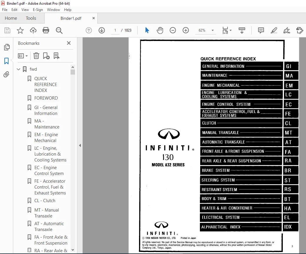
TABLE OF CONTENTS:
1999 INFINITI I30 A32 Series Service Manual PDF DOWNLOAD
fwd......................................................................................................................................   1
	QUICK REFERENCE INDEX................................................................................................................   1
	FOREWORD.............................................................................................................................   2
	GI - General Information.............................................................................................................   0
	MA - Maintenance.....................................................................................................................   0
	EM - Engine Mechanical...............................................................................................................   0
	LC - Engine, Lubrication & Cooling Systems...........................................................................................   0
	EC - Engine Control System...........................................................................................................   0
	FE - Accelerator Control, Fuel & Exhaust Systems.....................................................................................   0
	CL - Clutch..........................................................................................................................   0
	MT - Manual Transaxle................................................................................................................   0
	AT - Automatic Transaxle.............................................................................................................   0
	FA - Front Axle & Front Suspension...................................................................................................   0
	RA - Rear Axle & Rear Suspension.....................................................................................................   0
	BR - Brake System....................................................................................................................   0
	ST - Steering System.................................................................................................................   0
	RS - Restraint System................................................................................................................   0
	BT - Body & Trim.....................................................................................................................   0
	HA - Heater & Air Conditioner........................................................................................................   0
	EL - Electrical System...............................................................................................................   0
	IDX - Alphabetical Index.............................................................................................................   1
	Comment Sheet........................................................................................................................   3
	Inches to Metric Conversion..........................................................................................................   4
	Quick Reference Chart................................................................................................................   5
	GST Mode 6 - Test Value & Test Limit - CAL Models....................................................................................   6
	GST Mode 6 - Test Value & Test Limit - FED Models....................................................................................   7
at.......................................................................................................................................   8
	QUICK REFERENCE INDEX................................................................................................................   0
	TABLE OF CONTENTS....................................................................................................................   8
	DIAGNOSTIC TROUBLE CODE INDEX........................................................................................................  10
		Alphabetical & P No. Index for DTC...............................................................................................  10
	PRECAUTIONS AND PREPARATION..........................................................................................................  11
		Supplemental Restraint System (SRS) "AIR BAG" and 'SEAT BELT PRE-TENSIONER"......................................................  11
		Precautions for On Board Diagnostic (OBD)........................................................................................  11
		System of System A/T and Engine..................................................................................................  11
		Precautions......................................................................................................................  12
		Service Notice or Precautions....................................................................................................  13
		Special Service Tools............................................................................................................  15
		Commercial Service Tools.........................................................................................................  18
	OVERALL SYSTEM.......................................................................................................................  19
		A/T Electrical Parts Location....................................................................................................  19
		Circuit Diagram for Quick Pinpoint Check.........................................................................................  20
		Wiring Diagram - AT -............................................................................................................  21
		Cross-sectional View.............................................................................................................  27
		Hydraulic Control Circuit........................................................................................................  28
		Shift Mechanism..................................................................................................................  29
		Control System...................................................................................................................  38
		Control Mechanism................................................................................................................  40
		Control Valve....................................................................................................................  45
	ON BOARD DIAGNOSTIC SYSTEM DESCRIPTION...............................................................................................  46
		Introduction.....................................................................................................................  46
		OBD-II Function for A/T System...................................................................................................  46
		One or Two Trip Detection Logic of OBD-II........................................................................................  46
		OBD-II Diagnostic Trouble Code (DTC).............................................................................................  46
		Malfunction Indicator Lamp (MIL).................................................................................................  50
		CONSULT..........................................................................................................................  50
		Diagnostic Procedure without CONSULT.............................................................................................  57
	TROUBLE DIAGNOSIS - Introduction.....................................................................................................  61
		Introduction.....................................................................................................................  61
		Diagnostic Worksheet.............................................................................................................  62
		Work Flow........................................................................................................................  65
	TROUBLE DIAGNOSIS - Basic Inspection.................................................................................................  66
		A/T Fluid Check..................................................................................................................  66
		Stall Test.......................................................................................................................  66
		Line Pressure Test...............................................................................................................  69
		Road Test........................................................................................................................  70
	TROUBLE DIAGNOSIS - General Description..............................................................................................  81
		Symptom Chart....................................................................................................................  81
		TCM Terminals and Reference Value................................................................................................  84
	TROUBLE DIAGNOSIS FOR POWER SUPPLY...................................................................................................  87
		Main Power Supply and Ground Circuit.............................................................................................  87
	DTC P0705, Park/Neutral Position (PNP) Switch........................................................................................  88
	DTC P0710, A/T Fluid Temperature Sensor..............................................................................................  92
	DTC P0720, Vehicle Speed Sensor A/T (Revolution sensor)..............................................................................  96
	DTC P0725, Engine Speed Signal.......................................................................................................  99
	DTC P0731, A/T 1st Gear Function..................................................................................................... 102
	DTC P0732, A/T 2nd Gear Function..................................................................................................... 107
	DTC P0733, A/T 3rd Gear Function..................................................................................................... 112
	DTC P0734, A/T 4th Gear Function..................................................................................................... 117
	DTC P0740, Torque Converter Clutch Solenoid Valve.................................................................................... 125
	DTC P0744, A/T TCC S/V Function (Lock-up)............................................................................................ 129
	DTC P0745, Line Pressure Solenoid Valve.............................................................................................. 136
	DTC P0750, Shift Solenoid Valve A.................................................................................................... 140
	DTC P0755, Shift Solenoid Valve B.................................................................................................... 144
	DTC P1705, Throttle Position Sensor.................................................................................................. 148
	DTC P1760, Overrun Clutch Solenoid Valve............................................................................................. 156
	TROUBLE DIAGNOSIS FOR BATT/FLUID TEMP SEN............................................................................................ 158
		A/T Fluid Temperature Sensor Circuit and TCM Power Source........................................................................ 158
	TROUBLE DIAGNOSIS FOR VHCL SPEED SEN-MTR............................................................................................. 162
		Vehicle Speed Sensor - MTR....................................................................................................... 162
	TROUBLE DIAGNOSIS FOR CONTROL UNIT (RAM), CONTROL UNIT (ROM)......................................................................... 165
		TCM (Transmission Control Module)................................................................................................ 165
	TROUBLE DIAGNOSES FOR SYMPTOMS....................................................................................................... 167
		1. O/D OFF Indicator Lamp Does Not Come On....................................................................................... 167
		2. Engine Cannot Be Started In "P" and "N" Position.............................................................................. 168
		3. In "P" Position, Vehicle Moves Forward Or Backward When Pushed................................................................ 168
		4. In "N" Position, Vehicle Moves................................................................................................ 169
		5. Large Shock, "N" - "R" Position............................................................................................... 170
		6. Vehicle Does Not Creep Backward in "R" Position............................................................................... 171
		7. Vehicle Does Not Creep Forward in "D", "2" Or "1" Position.................................................................... 172
		8. Vehicle Cannot Be Started from D1............................................................................................. 173
		9. A/T Does Not Shift: D2 - D3................................................................................................... 174
		10. A/T Does Not Shift: D3 - D4.................................................................................................. 175
		11.  A/T Does Not Shift: D3 - D4................................................................................................. 176
		12. A/T Does Not Perform Lock-up................................................................................................. 177
		13. A/T Does Not Hold Lock-up Condition.......................................................................................... 178
		14. Lock-up Is Not Released...................................................................................................... 178
		15. Engine Speed Does Not Return To Idle (Light Braking D4 - D3)................................................................. 179
		16. Vehicle Does No Start From D1................................................................................................ 180
		17. A/T Does Not Shift: D4 - D3, When Overdrive Control Switch "ON" - "OFF"...................................................... 180
		18. A/T Does Not Shift: D3 - 22, When Selector Lever "D" - "2" Position.......................................................... 181
		19. A/T Does Not Shift: 22 - 11, When Selector Lever "2" - "1" Position.......................................................... 181
		20. Vehicle Does Not Decelerate By Engine Brake.................................................................................. 182
		21. TCM Self-diagnosis Does Not Activate (Park/Neutral Position, Overdrive Control and Throttle Position Switch Circuit Check.... 182
	TROUBLE DIAGNOSES - A/T SHIFT LOCK SYSTEM............................................................................................ 188
		Description...................................................................................................................... 188
		Shift Lock System Electrical Parts Location...................................................................................... 188
		Wiring Diagram - SHIFT -......................................................................................................... 189
		Diagnostic Procedure............................................................................................................. 190
		Key Interlock Cable.............................................................................................................. 192
		Component Check.................................................................................................................. 193
	ON-VEHICLE SERVICE................................................................................................................... 195
		Control Valve Assembly and Accumulator........................................................................................... 195
		Revolution Sensor Replacement.................................................................................................... 196
		Park/Neutral Position Switch Adjustment.......................................................................................... 196
		Control Cable Adjustment......................................................................................................... 197
		Differential Side Oil Seal Replacement........................................................................................... 197
	REMOVAL AND INSTALLATION............................................................................................................. 198
		Removal.......................................................................................................................... 198
		Installation..................................................................................................................... 199
	MAJOR OVERHAUL....................................................................................................................... 201
		Locations of Adjusting Shims, Needle Bearings, Thrust Washers and Snap Rings..................................................... 204
		Oil Channel...................................................................................................................... 205
	DISASSEMBLY.......................................................................................................................... 206
	REPAIR FOR COMPONENT PARTS........................................................................................................... 220
		Manual Shaft..................................................................................................................... 220
		Oil Pump......................................................................................................................... 222
		Control Valve Assembly........................................................................................................... 226
		Control Valve Upper Body......................................................................................................... 234
		Control Valve Lower Body......................................................................................................... 238
		Reverse Clutch................................................................................................................... 240
		High Clutch...................................................................................................................... 243
		Forward Clutch and Overrun Clutch................................................................................................ 247
		Low & Reverse Brake.............................................................................................................. 253
		Rear Internal Gear, Forward Clutch Hub and Overrun Clutch Hub.................................................................... 255
		Output Shaft, Idler Gear, Reduction Pinion Gear and Bearing Retainer............................................................. 259
		Band Servo Piston Assembly....................................................................................................... 264
		Final Drive...................................................................................................................... 269
	ASSEMBLY............................................................................................................................. 274
		Assembly 1....................................................................................................................... 274
		Adjustment 1..................................................................................................................... 274
		Assembly 2....................................................................................................................... 279
		Adjustment 2..................................................................................................................... 285
		Assembly 3....................................................................................................................... 287
	SERVICE DATA AND SPECIFICATIONS (SDS)................................................................................................ 293
		General Specifications........................................................................................................... 293
		Specifications and Adjustments................................................................................................... 293
br....................................................................................................................................... 300
	QUICK REFERENCE INDEX................................................................................................................   0
	TABLE OF CONTENTS.................................................................................................................... 300
	PRECAUTIONS AND PREPARATION.......................................................................................................... 302
		Supplemental Restraint System (SRS) "AIR BAG" and SEAT BELT PRE-TENSIONER"....................................................... 302
		Precautions for Brake System..................................................................................................... 302
		Commercial Service Tools......................................................................................................... 303
	NOISE, VIBRATION AND HARSHNESS (NVH) TROUBLESHOOTING................................................................................. 304
		NVH Troubleshooting Chart........................................................................................................ 304
	ON-VEHICLE SERVICE................................................................................................................... 305
		Checking Brake Fluid Level....................................................................................................... 305
		Checking Brake Line.............................................................................................................. 305
		Changing Brake Fluid............................................................................................................. 305
		Brake Burnishing Procedure....................................................................................................... 305
		Bleeding Brake System............................................................................................................ 306
	BRAKE HYDRAULIC LINE/CONTROL VALVE................................................................................................... 307
		Brake Hydraulic Line............................................................................................................. 307
		Dual Proportioning Valve......................................................................................................... 308
	BRAKE PEDAL AND BRACKET.............................................................................................................. 309
		Removal and Installation......................................................................................................... 309
		Inspection....................................................................................................................... 309
		Adjustment....................................................................................................................... 309
	MASTER CYLINDER...................................................................................................................... 310
		Removal ......................................................................................................................... 310
		Disassembly...................................................................................................................... 310
		Inspection....................................................................................................................... 311
		Assembly......................................................................................................................... 311
		Installation..................................................................................................................... 311
	BRAKE BOOSTER/VACUUM HOSE............................................................................................................ 312
		Brake Booster.................................................................................................................... 312
		Vacuum Hose...................................................................................................................... 313
	FRONT DISC BRAKE..................................................................................................................... 314
	Pad Replacement...................................................................................................................... 314
		Component........................................................................................................................ 315
		Removal.......................................................................................................................... 315
		Disassembly...................................................................................................................... 315
		Inspection - Caliper............................................................................................................. 316
		Inspection - Rotor............................................................................................................... 316
		Assembly......................................................................................................................... 317
		Installation..................................................................................................................... 317
	REAR DISC BRAKE...................................................................................................................... 318
		Pad Replacement.................................................................................................................. 318
		Component........................................................................................................................ 320
		Removal.......................................................................................................................... 321
		Disassembly...................................................................................................................... 321
		Inspection - Caliper............................................................................................................. 322
		Inspection - Rotor............................................................................................................... 323
		Assembly......................................................................................................................... 323
		Installation..................................................................................................................... 324
	PARKING BRAKE CONTROL................................................................................................................ 326
		Removal and Installation......................................................................................................... 326
		Inspection....................................................................................................................... 327
		Adjustment....................................................................................................................... 327
	ANTI-LOCK BRAKE SYSTEM (ABS) AND TRACTION CONTROL SYSTEM (TCS)....................................................................... 328
		Purpose.......................................................................................................................... 328
		ABS (Anti-Lock Brake System) Operation........................................................................................... 328
		ABS Hydraulic Circuit............................................................................................................ 328
		TCS (Traction Control System) Operation.......................................................................................... 329
		System Components................................................................................................................ 329
		System Description............................................................................................................... 329
		Removal and Installation......................................................................................................... 331
	TROUBLE DIAGNOSES.................................................................................................................... 333
		How to Perform Trouble Diagnoses for Quick and Accurate Repair................................................................... 333
		Preliminary Check................................................................................................................ 334
		Component Parts and Harness Connector Location................................................................................... 335
		Schematic........................................................................................................................ 336
		Wiring Diagram - ABS/TCS -....................................................................................................... 337
		Self-diagnosis................................................................................................................... 341
		CONSULT.......................................................................................................................... 344
		CONSULT Inspection Procedure..................................................................................................... 345
		Ground Circuit Check............................................................................................................. 352
	TROUBLE DIAGNOSES FOR SELF-DIAGNOSTIC ITEMS.......................................................................................... 353
		Diagnostic Procedure 1 (ENGINE CHECK SIGNAL - Engine System)..................................................................... 353
		Diagnostic Procedure 2 (ENGINE SPEED SIG - Engine speed signal).................................................................. 354
		Diagnostic Procedure 3 (LAN SIGNAL 1 - LAN monitoring)........................................................................... 355
		Diagnostic Procedure 4 (LAN SIGNAL 2 - LAN communication start procedure incomplete)............................................. 356
		Diagnostic Procedure 5 (LAN CIRCUITS 1, LAN CIRCUITS 2 - LAN communication system failure)....................................... 356
		Diagnostic Procedure 6 (LAN SIGNAL 3 - Continuied reception after LAN communication starts)...................................... 357
		Diagnostic Procedure 7 (ABS actuator solenoid valve)............................................................................. 358
		Diagnostic Procedure 8 (Wheel sensor or rotor)................................................................................... 360
		Diagnostic Procedure 9 (ABS MOTOR - Motor relay or motor)........................................................................ 362
		Diagnostic Procedure 10 (ABS ACTUATOR RELAY - Solenoid valve relay).............................................................. 366
		Diagnostic Procedure 11 (BATTERY VOLTAGE - Low or high voltage).................................................................. 367
		Diagnostic Procedure 12 (Control unit)........................................................................................... 368
	TROUBLE DIAGNOSES FOR SYMPTOMS....................................................................................................... 369
		Diagnostic Procedure 13 (Pedal vibration and noise).............................................................................. 369
		Diagnostic Procedure 14 (Long stopping distance)................................................................................. 370
		Diagnostic Procedure 15 (Unexpected pedal action)................................................................................ 370
		Diagnostic Procedure 16 (ABS does not work)...................................................................................... 371
		Diagnostic Procedure 17 (ABS works frequently)................................................................................... 371
		Diagnostic Procedure 18 (SLIP indicator lamp does not come on when ignition switch is turned on)................................. 372
		Diagnostic 19 (TCS OFF indicator lamp does not come on when ignition switch is turned on)........................................ 373
		Diagnostic Procedure 20 (ABS warning lamp does not come one when ignition switch is turned on)................................... 374
		Diagnostic Procedure 21 (ABS warning lamp stays on continuously.................................................................. 375
		Diagnostic Procedure 22 (TCS OFF switch is inoperative).......................................................................... 378
		Diagnostic Procedure 23 (Poor acceleration)...................................................................................... 379
	SERVICE DATA AND SPECIFICATIONS (SDS)................................................................................................ 380
		General Specifications........................................................................................................... 380
		Inspection and Adjustment........................................................................................................ 380
bt....................................................................................................................................... 381
	QUICK REFERENCE INDEX................................................................................................................   0
	TABLE OF CONTENTS.................................................................................................................... 381
	PRECAUTIONS.......................................................................................................................... 382
		Service Notice................................................................................................................... 382
		Supplemental Restraint System (SRS) "AIR BAG" and "SEAT BELT PRE-TENSIONER....................................................... 382
	GENERAL SERVICING.................................................................................................................... 383
		Clip and Fastener................................................................................................................ 383
	BODY END............................................................................................................................. 385
		Body Front End................................................................................................................... 385
		Body Rear End and Opener......................................................................................................... 388
	DOOR................................................................................................................................. 391
		Front Door....................................................................................................................... 391
		Rear Door........................................................................................................................ 392
	INSTRUMENT PANEL..................................................................................................................... 393
	INTERIOR TRIM........................................................................................................................ 396
		Side and Floor Trim.............................................................................................................. 396
		Door Trim........................................................................................................................ 398
		Roof Trim........................................................................................................................ 399
		Trunk Room Trim.................................................................................................................. 400
	EXTERIOR............................................................................................................................. 401
	SEAT................................................................................................................................. 407
		Front Seat....................................................................................................................... 408
		Heated Seat...................................................................................................................... 409
		Rear Seat........................................................................................................................ 410
	SUNROOF.............................................................................................................................. 411
		Trouble Diagnoses................................................................................................................ 415
	WINDSHIELD AND WINDOWS............................................................................................................... 419
		Windshield and Rear Window....................................................................................................... 420
	MIRROR............................................................................................................................... 421
		Door Mirror...................................................................................................................... 421
	BODY ALIGNMENT....................................................................................................................... 422
		Engine Compartment............................................................................................................... 422
		Underbody........................................................................................................................ 424
cl....................................................................................................................................... 426
	QUICK REFERENCE INDEX................................................................................................................   0
	TABLE OF CONTENTS.................................................................................................................... 426
	PRECAUTIONS AND PREPARATION.......................................................................................................... 427
		Precautions...................................................................................................................... 427
		Special Service Tools............................................................................................................ 427
	NOISE, VIBRATION AND HARSHNESS (NVH) TROUBLESHOOTING................................................................................. 428
		NVH Troubleshooting Chart........................................................................................................ 428
	CLUTCH SYSTEM - Hydraulic Type....................................................................................................... 429
	INSPECTION AND ADJUSTMENT............................................................................................................ 430
		Adjusting Clutch Pedal........................................................................................................... 430
		Bleeding Procedure............................................................................................................... 431
	HYDRAULIC CLUTCH CONTROL............................................................................................................. 432
		Clutch Master Cylinder........................................................................................................... 432
		Operating Cylinder............................................................................................................... 433
	CLUTCH RELEASE MECHANISM............................................................................................................. 434
	CLUTCH DISC AND CLUTCH COVER......................................................................................................... 435
		Clutch Disc...................................................................................................................... 435
		Clutch Cover and Flywheel........................................................................................................ 436
	SERVICE DATA AND SPECIFICATIONS (SDS)................................................................................................ 437
		General Specifications........................................................................................................... 437
		Inspection and Adjustment........................................................................................................ 437
ec....................................................................................................................................... 438
	QUICK REFERENCE INDEX................................................................................................................   0
	TABLE OF CONTENTS.................................................................................................................... 438
	DIAGNOSTIC TROUBLE CODE INDEX........................................................................................................ 441
		Alphabetical & P No. Index for DTC............................................................................................... 441
	PRECAUTIONS AND PREPARATION.......................................................................................................... 445
		Special Service Tool............................................................................................................. 445
		Commercial Service Tools......................................................................................................... 445
		Supplemental Restraint System (SRS) "AIR BAG" and "SEAT BELT PRE-TENSIONER"...................................................... 446
		Precautions for On Board Diagnostic (OBD)........................................................................................ 446
		System of Engine and A/T......................................................................................................... 446
		Engine Fuel & Emission Control System............................................................................................ 447
		Precautions...................................................................................................................... 448
	ENGINE AND EMISSION CONTROL OVERALL SYSTEM........................................................................................... 450
		Circuit Diagram.................................................................................................................. 450
		System Diagram................................................................................................................... 451
		Engine Control Component Parts Location.......................................................................................... 453
		Vacuum Hose Drawing.............................................................................................................. 457
		System Chart..................................................................................................................... 459
	ENGINE AND EMISSION BASIC CONTROL SYSTEM DESCRIPTION................................................................................. 460
		Multiport Fuel Injection (MFI) System............................................................................................ 460
		Electronic Ignition (EI) System.................................................................................................. 462
		Air Conditioning Cut Control..................................................................................................... 463
		Fuel Cut Control (at no load & high engine speed)................................................................................ 464
	EVAPORATIVE EMISSION SYSTEM.......................................................................................................... 465
		Description...................................................................................................................... 465
		Inspection....................................................................................................................... 465
		Evaporative Emission Line Drawing................................................................................................ 468
		On Board Refueling Vapor Recovery (ORVR)......................................................................................... 470
	POSITIVE CRANKCASE VENTILATION....................................................................................................... 475
		Description...................................................................................................................... 475
		Inspection....................................................................................................................... 475
	BASIC SERVICE PROCEDURE.............................................................................................................. 476
		Fuel Pressure Release............................................................................................................ 476
		Fuel Pressure Check.............................................................................................................. 476
		Injector Removal and Installation................................................................................................ 477
		Fast Idle Cam (FIC) Inspection and Adjustment.................................................................................... 478
		Direct Ignition System - How to Check Idle Speed and Ignition Timing............................................................. 479
		Idle Speed/Ignition Timing/Idle Mixture Ratio Adjustment......................................................................... 481
	ON BOARD DIAGNOSTIC SYSTEM DESCRIPTION............................................................................................... 489
		Introduction..................................................................................................................... 489
		Two Trip Detection Logic......................................................................................................... 489
		Emission-related Diagnostic Information.......................................................................................... 490
		Malfunction Indicator Lamp (MIL)................................................................................................. 503
		OBD System Operation Chart....................................................................................................... 507
		CONSULT.......................................................................................................................... 512
		Generic Scan Tool (GST).......................................................................................................... 525
	TROUBLE DIAGNOSIS - General Description.............................................................................................. 527
		Introduction..................................................................................................................... 527
		Diagnostic Worksheet............................................................................................................. 527
		Work Flow........................................................................................................................ 529
		Description for Work Flow........................................................................................................ 530
		Basic Inspection................................................................................................................. 531
		Diagnostic Trouble Code (DTC) Inspection Priority Chart.......................................................................... 537
		Fail-safe Chart.................................................................................................................. 538
		Symptom Matrix Chart............................................................................................................. 539
		CONSULT Reference Value in Data Monitor Mode..................................................................................... 542
		Major Sensor Reference Graph in Data Monitor Mode................................................................................ 545
		ECM Terminals and Reference Value................................................................................................ 547
	TROUBLE DIAGNOSIS FOR INTERMITTENT INCIDENT.......................................................................................... 555
		Description...................................................................................................................... 555
		Common I/I Report Situations..................................................................................................... 555
		Diagnostic Procedure............................................................................................................. 555
	TROUBLE DIAGNOSIS FOR POWER SUPPLY................................................................................................... 556
		Main Power Supply and Ground Circuit............................................................................................. 556
	DTC P0100, Mass Air Flow Sensor (MAFS)............................................................................................... 561
	DTC P0105, Absolute Pressure Sensor.................................................................................................. 569
	DTC P0110, Intake Air Temperature Sensor............................................................................................. 578
	DTC P0115, Engine Coolant Temperature Sensor (ECTS).................................................................................. 584
	DTC P0120, Throttle Position Sensor.................................................................................................. 589
	DTC P0125, Engine Coolant Temperature Sensor (ECTS).................................................................................. 600
	DTC P0130 (-B1), P0150 (-B2), Front Heated Oxygen Sensors (front HO2S) (P0130: Right bank) (P1050: Left bank) (Circuit).............. 605
	DTC P0131 (-B1) P0151 (-B2), Front Heated Oxygen Sensor (Lean shift monitoring) (Front HO2S) (P0131: Right bank) (P0151: Left........ 613
	DTC P0132 (-B1), P0152 (-B2), Front Heated Oxygen Sensor (Rich shift monitoring) (Front HO2S) (P0132: Right bank), (P0152: Le........ 619
	DTC P0133 (-B1), P0153 (-B2), Front Heated Oxygen Sensor (Response monitoring) (Front (HO2S) (P0132: Right bank) (P0152: Left........ 625
	DTC P0134 (-B1), P0154 (-B2), Front Heated Oxygen Sensor (High voltage) (Front HO2S) (P0134: Right bank), (P0154: Left bank)......... 635
	DTC P0135 (-B1), P0155 (-B2), Front Heated Oxygen Sensor Heater (P0135: Right bank), (P0155: Left bank).............................. 643
	DTC P0137 (-B1), P0157 (-B2)  FOR CALIFORNIA, Rear Heated Oxygen Sensor (Max. Voltage Monitoring) (Rear HO2S) (P0138: Right b........ 649
	DTC P0138 (-B1), P0158 (-B2) FOR CALIFORNIA, Rear Heated Oxygen Sensor (Max. Voltage Monitoring) (Rear HO2S) (P0138: Right ba........ 658
	DTC P0139 (-B1), P0159 (-B2), P0159 (-B2) FOR CALIFORNIA, Rear Heated Oxygen Sensor (Response Monitoring) (Rear HO2S) (P0139:........ 666
	DTC P0140 (-B1), P0160 (-B2) FOR CALIFORNIA, Rear Heated Oxygen Sensor (High voltage) (Rear HO2S) (P0141: Right bank), (P0160........ 674
	DTC P0137 EXCEPT FOR CALIFORNIA, Rear Heated Oxygen Sensor (Min. Voltage Monitoring) (Rear HO2S)..................................... 680
	DTC P0138 EXCEPT FOR CALIFORNIA, Rear Heated Oxygen Sensor (Max. Voltage Monitoring) (Rear H(2S)..................................... 687
	DTC P0139 EXCEPT FOR CALIFORNIA, Rear Heated Oxygen Sensor (Response Monitoring) (Rear HO2S)......................................... 694
	DTC P0140 EXCEPT FOR CALIFORNIA, Rear Heated Oxygen Sensor (High Voltage) (Rear HO2S)................................................ 701
	DTC P0141 (-B1), P0161 (-B2) FOR CALIFORNIA, Rear Heated Oxygen Sensor Heaters (P0141: Right bank), (P0161: Left bank)............... 706
	DTC P0141 EXCEPT FOR CALIFORNIA, Rear Heated Oxygen Sensor Heater.................................................................... 712
	DTC P0171 (-B1), P0174 (-B2), Fuel Inection System Function (Lean side) (P0171: Right bank), (P0174: Left bank)...................... 717
	DTC P0172 (-B1), P0175 (-B2), Fuel Injection System Function (Rich side) (P0172: Right bank), (P0175: Left bank)..................... 723
	DTC P0180, Tank Fuel Temperature Sensor.............................................................................................. 729
	DTC P0306 - P0300, No. 6 - 1 Cylinder Misfire, Multiple Cylinder Misfire............................................................. 733
	DTC P0325, Knock Sensor (KS)......................................................................................................... 738
	DTC P0335, Crankshaft Position Sensor (CKPS) (POS)................................................................................... 742
	DTC P0340, Camshaft Position Sensor (CMPS) (PHASE)................................................................................... 749
	DTC P0400, EGR Function (Close)...................................................................................................... 754
	DTC P0403, EGR Volume Control Valve (Circuit)........................................................................................ 763
	DTC P0420 (-B1), P0430 (-B2) FOR CALIFORNIA, Three Way Catalyst Function (P0420: Right bank), (P0430: Left bank)..................... 769
	DTC P0420 EXCEPT FOR CALIFORNIA, Three Way Catalyst Function......................................................................... 772
	DTC P0440, Evaporative Emission (EVAP) Control System (Small Leak) (Negative Pressure)............................................... 776
	DTC P0443, Evaporative Emission (EVAP) Canister Purge Volume Control Solenoid Valve (Circuit)........................................ 786
	DTC P0446, Evaporative Emission (EVAP) Canister Vent Control Valve (Circuit)......................................................... 792
	DTC P0450, Evaporative Emission (EVAP) Control System Pressure Sensor................................................................ 797
	DTC P0500, Vehicle Speed Sensor (VSS)................................................................................................ 803
	DTC P0505, Idle Control Valve (IACV) - Auxiliary Air Control (AAC) Valve............................................................. 807
	DTC P0510, Closed Throttle Position Switch........................................................................................... 814
	DTC P0600, P1605, A/T Communication Line (P0600) and A/T Diagnostic Communication Line (P1605)....................................... 819
	DTC P0605, Engine Control Module (ECM)............................................................................................... 822
	DTC P1105, Manifold Absolute Pressure (Map)/Barometric Pressure (BARO) Switch Solenoid Valve......................................... 824
	DTC P1130, Swirl Control Valve Control Solenoid Valve (Only for California).......................................................... 833
	DTC P1148 (-B1), P1168 (-B2), Closed Loop Control.................................................................................... 846
	DTC P1165, Swirl Control Valve Control Vacuum Check Switch (Only for California)..................................................... 848
	DTC P1320, Ignition Signal........................................................................................................... 853
	DTC P1335, Crankshaft Position Sensor (CKPS) (REF)................................................................................... 860
	DTC P1336, Crankshaft Position Sensor (CKPS) (POS) (COG)............................................................................. 866
	DTC P1401, EGR Temperature Sensor.................................................................................................... 873
	DTC P1402, EGR Function (Open)....................................................................................................... 879
	DTC P1440, Evaporative Emission (EVAP) Control System (Small Leak) (Positive Pressure................................................ 887
	DTC P1444, Evaporative Emission (EVAP) canister Purge Volume Control Solenoid Valve.................................................. 897
	DTC P1446, Evaporative Emission (EVAP) Canister Vent Control Valve (Close)........................................................... 904
	DTC P1447, Evaporative Emission (EVAP) Control System Purge Flow Monitoring.......................................................... 909
	DTC P1448, Evaporative Emission (EVAP) Canister Vent Control Valve (Open)............................................................ 915
	DTC P1490, Vacuum Cut Valve Bypass Valve (Circuit)................................................................................... 921
	DTC P1491, Vacuum Cut Valve Bypass Valve............................................................................................. 926
	DTC P1706, Park/Neutral Position (PNO) Switch........................................................................................ 931
	TROUBLE DIAGNOSIS FOR ABS/TCS C/U SIGNAL............................................................................................. 936
		ABS/TCS Control Unit............................................................................................................. 936
	TROUBLE DIAGNOSIS FOR ECM - ABS/TCS COMM NG.......................................................................................... 939
		ABS/TCS Communication Line....................................................................................................... 939
	TROUBLE DIAGNOSIS FOR OVERHEAT....................................................................................................... 942
		Overheat......................................................................................................................... 942
	TROUBLE DIAGNOSIS FOR NON-DETECTAABLE ITEMS.......................................................................................... 955
		Injector ........................................................................................................................ 955
		Start Signal..................................................................................................................... 960
		Fuel Pump Control ............................................................................................................... 962
		Front Engine Mounting Control.................................................................................................... 966
		Power Steering Oil Pressure Switch............................................................................................... 969
		Electrical Load Signal........................................................................................................... 974
		MIL & Data Link Connectors....................................................................................................... 977
	SERVICE DATA AND SPECIFICATIONS (SDS)................................................................................................ 978
		General Specifications........................................................................................................... 978
		Inspection and Adjustment........................................................................................................ 978
el....................................................................................................................................... 980
	QUICK REFERENCE INDEX................................................................................................................   0
	TABLE OF CONTENTS.................................................................................................................... 980
	PRECAUTIONS.......................................................................................................................... 984
		Supplemental Restraint System (SRS) "AIR BAG" and "SEAT BELT PRE-TENSIONER"...................................................... 984
	HARNESS CONNECTOR.................................................................................................................... 985
		Description...................................................................................................................... 985
	STANDARDIZED RELAY................................................................................................................... 987
		Description...................................................................................................................... 987
	POWER SUPPLY ROUTING................................................................................................................. 989
		Schematic........................................................................................................................ 989
		Wiring Diagram - POWER - ........................................................................................................ 990
		Fuse............................................................................................................................. 997
		Fusible Link..................................................................................................................... 997
		Circuit Breaker Inspection....................................................................................................... 997
	GROUND DISTRIBUTION.................................................................................................................. 998
	BATTERY..............................................................................................................................1003
		How to Handle Battery............................................................................................................1003
		Service Data and Specifications (SDS)............................................................................................1006
	STARTING SYSTEM......................................................................................................................1007
		System Description...............................................................................................................1007
		Wiring Diagram - START - /M/T Models.............................................................................................1008
		Wiring Diagram - START - /A/T Models.............................................................................................1009
		Construction.....................................................................................................................1010
		Removal and Installation.........................................................................................................1010
		Pinion/Clutch Check..............................................................................................................1011
		Service Data and Specifications (SDS)............................................................................................1011
	CHARGING SYSTEM......................................................................................................................1012
		System Description...............................................................................................................1012
		Wiring Diagram - CHARGE -........................................................................................................1013
		Trouble Diagnoses................................................................................................................1014
		Construction.....................................................................................................................1015
		Removal and Installation.........................................................................................................1015
		Service Data and Specifications (SDS)............................................................................................1016
	COMBINATION SWITCH...................................................................................................................1017
		Check............................................................................................................................1017
		Replacement......................................................................................................................1018
	STEERING SWITCH......................................................................................................................1019
		Check............................................................................................................................1019
	HEADLAMP.............................................................................................................................1020
		Component Parts and Harness Connector Location...................................................................................1020
		System Description (For U.S.A)...................................................................................................1020
		Wiring Diagram (For U.S.A.) - H/LAMP -...........................................................................................1022
		Trouble Diagnoses/Auto Light Operation...........................................................................................1024
		Trouble Diagnoses/Headlamp.......................................................................................................1027
		Bulb Replacment..................................................................................................................1028
		Bulb Specifications..............................................................................................................1028
		Aiming Adjustment................................................................................................................1028
	HEADLAMP - Daytime Light System -....................................................................................................1030
		System Description (For Canada)..................................................................................................1030
		Operation (For Canada)...........................................................................................................1031
		Schematic (For Canada)...........................................................................................................1032
		Wiring Diagram (For Canada) - DTRL -.............................................................................................1033
		Trouble Diagnoses (For Canada)...................................................................................................1036
		Bulb Replacement.................................................................................................................1037
		Aiming Adjustment................................................................................................................1037
	PARKING, LICENSE AND TAIL LAMPS......................................................................................................1038
		Wiring Diagram - TAIL/L -........................................................................................................1038
		Trouble Diagnoses................................................................................................................1040
	TURN SIGNAL AND HAZARD WARNING LAMPS.................................................................................................1041
		System Description...............................................................................................................1041
		Wiring Diagram - TURN -..........................................................................................................1042
		Trouble Diagnoses................................................................................................................1044
		Electrical Components Inspection.................................................................................................1044
	STOP LAMP............................................................................................................................1046
		Wiring Diagram - STOP/L -........................................................................................................1046
	BACK-UP LAMP.........................................................................................................................1047
		Wiring Diagram - BACK/L -........................................................................................................1047
	FRONT FOG LAMP.......................................................................................................................1048
		System Description...............................................................................................................1048
		Wiring DIagram  F/FOG - /FOR U.S.A...............................................................................................1049
		Wiring Diagram - F/FOG - /FOR CANADA.............................................................................................1050
		Aiming Adjustment................................................................................................................1051
		Bulb Specifications..............................................................................................................1051
	CORNERING LAMP.......................................................................................................................1052
		System Description...............................................................................................................1052
		Wiring Diagram - CORNER -........................................................................................................1053
	ILLUMINATION.........................................................................................................................1055
		System Description...............................................................................................................1055
		Schematic........................................................................................................................1056
		Wiring Diagram - ILL -...........................................................................................................1057
	SPOT, VANITY MIRROR AND TRUNK ROOM LAMP..............................................................................................1061
		Wiring Diagram - INT/L...........................................................................................................1061
	METER AND GAUGES.....................................................................................................................1062
		System Description...............................................................................................................1062
		Combination Meter................................................................................................................1064
		Wiring Diagram - METER -.........................................................................................................1065
		Meter/Gauge Operation and Odo/Trip Meter Segment Check in Diagnosis Mode.........................................................1066
		Flexible Print Circuit (FPC).....................................................................................................1067
		Trouble Diagnoses................................................................................................................1068
		Electrical Components Inspection.................................................................................................1072
	WARNING LAMPS........................................................................................................................1074
		Schematic........................................................................................................................1074
		Wiring Diagram - WARN -..........................................................................................................1075
		Electrical Components Inspection.................................................................................................1079
	WARNING BUZZER.......................................................................................................................1080
		System Description...............................................................................................................1080
		Wiring Diagram - BUZZER -........................................................................................................1081
		CONSULT..........................................................................................................................1082
		Trouble Diagnoses................................................................................................................1083
	WIPER AND WASHER.....................................................................................................................1088
		System Description...............................................................................................................1088
		Wiring Diagram - WIPER -.........................................................................................................1090
		CONSULT..........................................................................................................................1092
		Trouble Diagnoses................................................................................................................1093
		Removal and Installation.........................................................................................................1098
		Washer Nozzle Adjustment.........................................................................................................1099
		Check Valve (Built in washer nozzles)............................................................................................1099
	HORN.................................................................................................................................1100
		Wiring Diagram - HORN -..........................................................................................................1100
	CIGARETTE LIGHTER....................................................................................................................1101
		Wiring Diagram - CIGAR -.........................................................................................................1101
	CLOCK................................................................................................................................1102
		Wiring Diagram - CLOCK -.........................................................................................................1102
	REAR WINDOW DEFOGGER.................................................................................................................1103
		System Description...............................................................................................................1103
		Wiring DIagram - DEF -...........................................................................................................1104
		CONSULT..........................................................................................................................1106
		Trouble Diagnoses................................................................................................................1107
		Filament Check...................................................................................................................1110
		Filament Repair..................................................................................................................1111
	AUDIO................................................................................................................................1112
		System Description...............................................................................................................1112
		Schematic .......................................................................................................................1113
		Wiring Diagram - AUDIO -.........................................................................................................1114
		Trouble Diagnoses................................................................................................................1117
	AUDIO ANTENNA........................................................................................................................1118
		System Description...............................................................................................................1118
		Wiring Diagram - P/ANT -.........................................................................................................1119
		Trouble Diagnoses................................................................................................................1120
		Location of Antenna..............................................................................................................1120
		Antenna Rod Replacement..........................................................................................................1121
		Window Antenna Repair............................................................................................................1122
	HANDSFREE TELEPHONE (Pre wire).......................................................................................................1123
		Wiring Diagram - H/PHON -........................................................................................................1123
	TELEPHONE (Pre wire).................................................................................................................1125
		Wiring Diagram  - PHONE -........................................................................................................1125
	ELECTRIC SUNROOF.....................................................................................................................1126
		System Description...............................................................................................................1126
		Wiring Diagram -SROOF -..........................................................................................................1127
	POWER SEAT...........................................................................................................................1128
		Wiring Diagram - SEAT -..........................................................................................................1128
	HEATED SEAT..........................................................................................................................1130
		Wiring Diagram - HSEAT -.........................................................................................................1130
	POWER DOOR MIRROR....................................................................................................................1131
		Wiring Diagram - MIRROR -........................................................................................................1131
	AUTO ANTI-DAZZLING INSIDE MIRROR.....................................................................................................1132
		Wiring Diagram - I/MIRR -........................................................................................................1132
	TRUNK LID AND FUEL FILLER LID OPENER.................................................................................................1133
		Wiring Diagram - TLID -..........................................................................................................1133
	AUTOMATIC SPEED CONTROL DEVICE (ASCD)................................................................................................1134
		Component Parts and Harness Connector Location...................................................................................1134
		System Description...............................................................................................................1135
		Schematic/M/T Models.............................................................................................................1137
		Schematic/A/T Models.............................................................................................................1138
		Wiring Diagram - ASCD -..........................................................................................................1139
		CONSULT..........................................................................................................................1144
		Fail-safe System Description.....................................................................................................1146
		Fail-safe System Check...........................................................................................................1147
		Trouble Diagnoses................................................................................................................1148
		Electrical Components Inspection.................................................................................................1156
		ASCD Wire Adjustment.............................................................................................................1157
	IVMS (LAN)...........................................................................................................................1158
		Overall Description..............................................................................................................1158
		Component Parts Location.........................................................................................................1159
		System Diagram...................................................................................................................1160
		Sleep/Wake-up Control............................................................................................................1161
		Fail-safe System.................................................................................................................1161
		CONSULT..........................................................................................................................1162
		On board Diagnosis...............................................................................................................1169
		On board Diagnosis - Mode I (VMS communication diagnosis)........................................................................1171
		On board Diagnosis - Mode II (Switch monitor)....................................................................................1172
		Wiring Diagram - COMM -..........................................................................................................1174
		Trouble Diagnoses................................................................................................................1177
	BCM (Body Control Module)............................................................................................................1181
		Schematic........................................................................................................................1181
		Input/Output Operation Signal....................................................................................................1182
	DRIVER DOOR CONTROL UNIT (LCU01).....................................................................................................1184
		Schematic........................................................................................................................1184
		Input/Output Operation Signal....................................................................................................1185
	PASSENGER DOOR CONTROL UNIT (LCU02)..................................................................................................1186
		Schematic........................................................................................................................1186
		Input/Output Operation Signal....................................................................................................1187
	REAR RH/LH DOOR CONTROL UNIT (LCU03/04)..............................................................................................1188
		Schematic........................................................................................................................1188
		Input/Output Operation Signal....................................................................................................1190
	MULTI-REMOTE CONTROL UNIT (LCU05)....................................................................................................1191
		Schematic........................................................................................................................1191
		Input/Output Operation Signal....................................................................................................1191
	POWER WINDOW - IVMS..................................................................................................................1192
		System Description...............................................................................................................1192
		Schematic........................................................................................................................1193
		Wiring Diagram - WINDOW - .......................................................................................................1194
		CONSULT..........................................................................................................................1198
		On board Diagnosis - Mode IV (Power window monitor)..............................................................................1199
		Trouble Diagnoses................................................................................................................1201
	POWER DOOR LOCK - IVMS...............................................................................................................1208
		System Description...............................................................................................................1208
		Schematic........................................................................................................................1209
		Wiring Diagram - D/LOCK -........................................................................................................1210
		CONSULT..........................................................................................................................1214
		On board Diagnosis - Mode III (Power door lock operation)........................................................................1217
		Trouble Diagnoses................................................................................................................1219
	MULTI-REMOTE CONTROL SYSTEM - IVMS...................................................................................................1227
		System Description...............................................................................................................1227
		Schematic........................................................................................................................1229
		Wiring Diagram - MULTI -.........................................................................................................1231
		CONSULT..........................................................................................................................1235
		Trouble Diagnoses................................................................................................................1236
		ID Code Entry Procedure..........................................................................................................1244
	THEFT WARNING SYSTEM - IVMS..........................................................................................................1245
		Component Parts and Harness Connector Location...................................................................................1245
		System Description...............................................................................................................1246
		Schematic........................................................................................................................1248
		Wiring Diagram - THEFT -.........................................................................................................1250
		CONSULT .........................................................................................................................1256
		Trouble Diagnoses................................................................................................................1257
	REAR POWER WINDOW SWITCH ILLUMINATION - IVMS.........................................................................................1272
		System Description...............................................................................................................1272
		Wiring Diagram - SW/ILL -........................................................................................................1273
		CONSULT..........................................................................................................................1274
		Trouble Diagnoses................................................................................................................1275
	INTERIOR LAMP CONTROL - IVMS.........................................................................................................1276
		System Description...............................................................................................................1276
		Wiring Diagram - ROOM/L -........................................................................................................1277
		CONSULT..........................................................................................................................1279
		Trouble Diagnoses................................................................................................................1280
	STEP LAMP - IVMS.....................................................................................................................1284
		System Description...............................................................................................................1284
		Wiring Diagram - STEP/L -........................................................................................................1285
		CONSULT..........................................................................................................................1287
		Trouble Diagnoses................................................................................................................1288
	IVIS (Infiniti Vehicle Immobilizer System - NATS )...................................................................................1290
		Component Parts and Harness Connector Location...................................................................................1290
		System Description...............................................................................................................1291
		System Composition...............................................................................................................1291
		Wiring Diagram - NATS -..........................................................................................................1292
		CONSULT..........................................................................................................................1293
		Trouble DIagnoses................................................................................................................1295
	INFINITI COMMUNICATOR (IVCS).........................................................................................................1305
		Precaution.......................................................................................................................1305
		Communicator Response Center Telephone Number for Technicians....................................................................1305
		Component Parts and Harness Connector Location...................................................................................1306
		System Description...............................................................................................................1307
		Schematic........................................................................................................................1313
		Wiring Diagram - IVCS............................................................................................................1314
		CONSULT..........................................................................................................................1318
		Trouble Diagnoses................................................................................................................1322
		Trouble Diagnoses for Intermittent Incident......................................................................................1332
		Demonstration Mode...............................................................................................................1333
		System Setting (When IVCS unit is replaced)......................................................................................1335
	INTEGRATED HOMELINK TRANSMITTER......................................................................................................1339
		Wiring Diagram - TRNSMT - .......................................................................................................1339
		Trouble Diagnoses................................................................................................................1340
	LOCATION OF ELECTRICAL UNITS.........................................................................................................1342
		Engine Compartment...............................................................................................................1342
		Passenger Compartment............................................................................................................1343
		Luggage Compartment..............................................................................................................1344
	HARNESS LAYOUT.......................................................................................................................1345
		Outline..........................................................................................................................1345
		How to Read Harness Layout.......................................................................................................1346
		Engine Room Harness..............................................................................................................1347
		Main Harness.....................................................................................................................1350
		Engine Control Harness...........................................................................................................1352
		Body Harness.....................................................................................................................1354
		Body No. 2 Harness...............................................................................................................1356
		Tail Harness.....................................................................................................................1356
		Room Lamp Harness................................................................................................................1357
		Air Bag Harness..................................................................................................................1358
		Door Harness (LH side)...........................................................................................................1359
		Door Harness (RH side)...........................................................................................................1360
	BULB SPECIFICATIONS..................................................................................................................1361
		Headlamp.........................................................................................................................1361
		Exterior Lamp....................................................................................................................1361
		Interior Lamp....................................................................................................................1361
	WIRING DIAGRAM CODES (Cell codes)....................................................................................................1362
	SUPER MULTIPLE JUNCTION (SMJ)........................................................................................................   0
		Terminal Arrangement.............................................................................................................   1
	FUSE BLOCK -Junction Box (J/B).......................................................................................................   2
		Terminal Arrangement.............................................................................................................   2
	FUSE AND FUSIBLE LINK BOX............................................................................................................   3
		Terminal Arrangement.............................................................................................................   2
	ELECTRICAL UNITS.....................................................................................................................   4
		Terminal Arrangement.............................................................................................................   4
	JOINT CONNECTOR (J/C)................................................................................................................   5
		Terminal Arrangement.............................................................................................................   5
em.......................................................................................................................................1364
	QUICK REFERENCE INDEX................................................................................................................   0
	TABLE OF CONTENTS....................................................................................................................1364
	PRECAUTIONS..........................................................................................................................1365
		Parts Requiring Angular Tightening...............................................................................................1365
		Liquid Gasket Application Procedure..............................................................................................1365
	PREPARATION..........................................................................................................................1366
		Special Service Tools............................................................................................................1366
		Commercial Service Tools.........................................................................................................1368
	NOISE, VIBRATION AND HARSHNESS (NVH) TROUBLESHOOTING.................................................................................1369
		NVH Troubleshooting - Engine Noise...............................................................................................1370
	OUTER COMPONENT PARTS................................................................................................................1371
	COMPRESSION PRESSURE.................................................................................................................1375
		Measurement of Compression Pressure..............................................................................................1375
	OIL PAN..............................................................................................................................1376
		Removal..........................................................................................................................1376
		Installation.....................................................................................................................1379
	TIMING CHAIN.........................................................................................................................1383
		Removal..........................................................................................................................1385
		Inspection.......................................................................................................................1392
		Installation.....................................................................................................................1392
	OIL SEAL REPLACEMENT.................................................................................................................1397
	CYLINDER HEAD........................................................................................................................1400
		Removal..........................................................................................................................1401
		Disassembly......................................................................................................................1401
		Inspection.......................................................................................................................1403
		Assembly.........................................................................................................................1408
		Installation.....................................................................................................................1408
	VALVE CLEARANCE......................................................................................................................1413
		Checking.........................................................................................................................1413
		Adjusting........................................................................................................................1414
	ENGINE REMOVAL.......................................................................................................................1417
		Removal .........................................................................................................................1418
		Installation.....................................................................................................................1419
	CYLINDER BLOCK.......................................................................................................................1420
		Disassembly......................................................................................................................1421
		Inspection.......................................................................................................................1421
		Assembly.........................................................................................................................1428
	SERVICE DATA AND SPECIFICATIONS (SDS)................................................................................................1431
		General Specifications...........................................................................................................1431
		Inspection and Adjustment........................................................................................................1431
fa.......................................................................................................................................1439
	QUICK REFERENCE INDEX................................................................................................................   0
	TABLE OF CONTENTS....................................................................................................................1439
	PRECAUTIONS AND PREPARATION..........................................................................................................1440
		Precautions......................................................................................................................1440
		Special Service Tools............................................................................................................1440
		Commercial Service Tools.........................................................................................................1441
	NOISE, VIBRATION AND HARSHNESS (NVH) TROUBLESHOOTING.................................................................................1442
		NVH Troubleshooting Chart........................................................................................................1442
	FRONT SUSPENSION SYSTEM..............................................................................................................1443
		Components.......................................................................................................................1443
	ON-VEHICLE SERVICE...................................................................................................................1444
		Front Axle and Front Suspension Parts............................................................................................1444
		Front Wheel Bearing..............................................................................................................1445
		Front Wheel Alignment............................................................................................................1445
		Drive Shaft......................................................................................................................1446
	FRONT AXLE...........................................................................................................................1447
		Wheel Hub and Knuckle............................................................................................................1447
		Drive Shaft......................................................................................................................1451
	FRONT SUSPENSION ....................................................................................................................1459
		Components.......................................................................................................................1459
		Coil Spring and Strut Assembly...................................................................................................1460
		Stabilizer Bar...................................................................................................................1461
		Transverse Link and Lower Ball Joint.............................................................................................1462
	SERVICE DATA AND SPECIFICATIONS (SDS)................................................................................................1464
		General Specifications...........................................................................................................1464
		Inspection and Adjustment........................................................................................................1464
fe.......................................................................................................................................1466
	QUICK REFERENCE INDEX................................................................................................................   0
	TABLE OF CONTENTS....................................................................................................................1466
	PREPARATION/ACCELERATOR CONTROL SYSTEM...............................................................................................1467
		Special Service Tool.............................................................................................................1467
		Adjusting Accelerator Wire.......................................................................................................1467
	FUEL SYSTEM..........................................................................................................................1468
	EXHAUST SYSTEM.......................................................................................................................1469
foldout..................................................................................................................................1471
	QUICK REFERENCE INDEX................................................................................................................   0
	SUPER MULTIPLE JUNCTION (SMJ)........................................................................................................1471
		TERMINAL ARRANGEMENT.............................................................................................................1472
	FUSE BLOCK - JUNCTION BOX (J/B)......................................................................................................1473
	FUSE AND FUSIBLE LINK BOX............................................................................................................1474
	ELECTRICAL UNITS.....................................................................................................................1475
	JOINT CONNECTOR (J/C)................................................................................................................1476
gi.......................................................................................................................................1477
	QUICK REFERENCE INDEX................................................................................................................   0
	TABLE OF CONTENTS....................................................................................................................1477
	PRECAUTIONS..........................................................................................................................1478
		Precautions for Supplemental Restraint System (SRS) "AIR BAG" and "SEAT BELT PRE-TENSIONER"......................................1478
		Precautions for IVIS (Infiniti Vehicle Immobiliser System-NATS)..................................................................1478
		Precautions for INFINITI Communicator (IVCS).....................................................................................1479
		General Precautions..............................................................................................................1479
		Precautions for Multiport Fuel Injection Systm or Engine Control System..........................................................1481
		Precautions for Three Way Catalyst...............................................................................................1481
		Precautions for Engine Oils......................................................................................................1481
		Precautions for Fuel.............................................................................................................1482
		Precautions for Air Conditioning.................................................................................................1483
	HOW TO USE THIS MANUAL...............................................................................................................1484
	HOW TO READ WIRING DIAGRAMS .........................................................................................................1486
		Sample/Wiring Diagram -EXAMPL-...................................................................................................1486
		Description......................................................................................................................1488
	HOW TO CHECK TERMINAL................................................................................................................1495
		Connector and Terminal Pin Kit...................................................................................................1495
		How to Probe Connectors..........................................................................................................1495
		How to Check Enlarged Contact Spring of Terminal.................................................................................1496
		Waterproof Connector Inspection..................................................................................................1497
		Terminal Lock Inspection.........................................................................................................1497
	HOW TO PERFORM EFFICIENT DIAGNOSIS FOR AN ELECTRICAL INCIDENT........................................................................1498
		Work Flow........................................................................................................................1498
		Incident Simulation Tests........................................................................................................1499
		Circuit Inspection...............................................................................................................1502
	HOW TO FOLLOW FLOW CHART IN TROUBLE DIAGNOSES........................................................................................1508
		How To Follow This Flow Chart....................................................................................................1509
	CONSULT CHECKING SYSTEM..............................................................................................................1513
		Function and System Application..................................................................................................1513
		Lithium Battery Replacement......................................................................................................1512
		Checking Equipment...............................................................................................................1512
		Loading Procedure................................................................................................................1512
		CONSULT Data Link Connector (DLC) Circuit........................................................................................1513
	IDENTIFICATION INFORMATION...........................................................................................................1514
		Model Variation..................................................................................................................1514
		Identification Number............................................................................................................1515
		Dimensions.......................................................................................................................1517
		Wheels and Tires.................................................................................................................1517
	LIFTING POINTS AND TOW TRUCK TOWING..................................................................................................1518
		Preparation......................................................................................................................1518
		Board-on Lift....................................................................................................................1518
		Garage Jack and Safety Stand.....................................................................................................1519
		2-pole Lift......................................................................................................................1520
		Tow Truck Towing.................................................................................................................1521
	TIGHTENING TORQUE OF STANDARD BOLTS..................................................................................................1522
	SAE J930 TERMINOLOGY LIST............................................................................................................1523
		SAE J1930 Terminology List.......................................................................................................1523
ha.......................................................................................................................................1527
	QUICK REFERENCE INDEX................................................................................................................   0
	TABLE OF CONTENTS....................................................................................................................1527
	PRECAUTIONS AND PREPARATION..........................................................................................................1528
		Supplemental Restraint System (SRS) "AIR BAG" and "SEAT BELT PRE-TENSIONER" .....................................................1528
		Precautions for Working with HFC-134a (R-134a)...................................................................................1528
		General Refrigerant Precautions..................................................................................................1528
		Precautions for Refrigerant Connection...........................................................................................1529
		Precautions for Servicing Compressor.............................................................................................1532
		Special Service Tools............................................................................................................1532
		HFC-134a (R-134a) Service Tools and Equipment....................................................................................1533
		Precautions for Service Equipment................................................................................................1535
	DESCRIPTION..........................................................................................................................1537
		Refrigeration Cycle..............................................................................................................1537
		V-6 Variable Displacement Compressor.............................................................................................1538
		Component Layout.................................................................................................................1542
		Discharge Air Flow...............................................................................................................1543
		Introduction.....................................................................................................................1544
		Features.........................................................................................................................1544
		Control Operation................................................................................................................1547
	TROUBLE DIAGNOSES....................................................................................................................1549
		How to Perform Trouble Diagnoses for Quick and Accurate Repair...................................................................1549
		Operational Check................................................................................................................1550
		Self-diagnosis...................................................................................................................1556
		Symptom Chart....................................................................................................................1554
		Preliminary Check................................................................................................................1565
		Performance Test Diagnoses.......................................................................................................1573
		Performance Chart................................................................................................................1575
		Trouble Diagnoses for Abnormal Pressure..........................................................................................1576
		Component Location...............................................................................................................1579
		Circuit Diagram..................................................................................................................1581
		Wiring Diagram - A/C, A -........................................................................................................1582
		Main Power Supply and Ground Circuit Check.......................................................................................1585
		Diagnostic Procedure 1...........................................................................................................1586
		Diagnostic Procedure 2...........................................................................................................1587
		Diagnostic Procedure 3...........................................................................................................1588
		Diagnostic Procedure 4...........................................................................................................1589
		Diagnostic Procedure 5...........................................................................................................1590
		Diagnostic Procedure 6...........................................................................................................1591
		Diagnostic Procedure 7...........................................................................................................1592
		Diagnostic Procedure 8...........................................................................................................1594
		Diagnostic Procedure 9...........................................................................................................1596
		Electrical Components Inspection.................................................................................................1598
		Control Linkage Adjustment.......................................................................................................1599
	SYSTEM DESCRIPTION...................................................................................................................1601
		Overview of Control System.......................................................................................................1601
		Control System Input Components..................................................................................................1602
		Control System Automatic Amplifier (Auto amp.)...................................................................................1604
		Control System Output Components.................................................................................................1605
	SERVICE PROCEDURES...................................................................................................................1613
		HFC-134a (R-134a) Service Procedure..............................................................................................1613
		Maintenance of Lubricant Quantity in Compressor..................................................................................1615
		Refrigerant Lines................................................................................................................1617
		Checking Refrigerant Leaks.......................................................................................................1618
		Compressor Mounting..............................................................................................................1621
		Belt Tension.....................................................................................................................1621
		Fast Idle Control Device (FICD)..................................................................................................1621
		Compressor.......................................................................................................................1622
		Compressor Clutch................................................................................................................1622
	SERVICE DATA AND SPECIFICATIONS (SDS)................................................................................................1622
		General Specifications...........................................................................................................1626
		Inspection and Adjustment........................................................................................................1626
idx......................................................................................................................................1627
	QUICK REFERENCE INDEX................................................................................................................   0
lc.......................................................................................................................................1635
	QUICK REFERENCE INDEX................................................................................................................   0
	TABLE OF CONTENTS....................................................................................................................1635
	PRECAUTIONS AND PREPARATION..........................................................................................................1636
		Liquid Gasket Application Procedure..............................................................................................1636
		Special Service Tools............................................................................................................1637
	ENGINE LUBRICATION SYSTEM............................................................................................................1638
		Lubrication Circuit..............................................................................................................1638
		Oil Pressure Check...............................................................................................................1639
		Oil Pump.........................................................................................................................1639
	ENGINE COOLING SYSTEM................................................................................................................1642
		Cooling Circuit..................................................................................................................1642
		System Check.....................................................................................................................1643
		Water Pump.......................................................................................................................1644
		Thermostat.......................................................................................................................1648
		Radiator.........................................................................................................................1649
		Cooling Fan Control System.......................................................................................................1649
		Radiator (Aluminum type).........................................................................................................1650
		Overheating Cause Analysis.......................................................................................................1653
	SERVICE DATA AND SPECIFICATIONS (SDS)................................................................................................1654
		Engine Lubrication System .......................................................................................................1654
		Engine Cooling System............................................................................................................1654
ma.......................................................................................................................................1655
	QUICK REFERENCE INDEX................................................................................................................   0
	TABLE OF CONTENTS....................................................................................................................1655
	PRECAUTIONS AND PREPARATION..........................................................................................................1656
		Supplemental Restraint System (SRS) "AIR BAG" and "SEAT BELT PRE-TENSIONER"......................................................1656
		Special Service Tool.............................................................................................................1656
		Commercial Service Tool..........................................................................................................1656
	GENERAL MAINTENANCE..................................................................................................................1657
	PERIODIC MAINTENANCE.................................................................................................................1659
		Schedule 1.......................................................................................................................1660
		Schedule 2.......................................................................................................................1661
	RECOMMENDED FLUIDS AND LUBRICATNS....................................................................................................1662
		Fluids and Lubricants............................................................................................................1662
		SAE Viscosity Number.............................................................................................................1662
		Anti-freeze Coolant Mixture Ratio................................................................................................1663
	ENGINE MAINTENANCE...................................................................................................................1664
		Checking Drive Belts.............................................................................................................1664
		Changing Engine Coolant..........................................................................................................1665
		Checking Fuel Lines..............................................................................................................1666
		Changing Fuel Filter.............................................................................................................1667
		Changing Air Cleaner Filter......................................................................................................1667
		Changing Engine Oil..............................................................................................................1668
		Changing Oil Filter..............................................................................................................1668
		Changing Spark Plugs.............................................................................................................1669
		Checking EVAP Vapor Lines........................................................................................................1670
	CHASSIS AND BODY MAINTENANCE.........................................................................................................1671
		Checking Exhaust System..........................................................................................................1671
		Checking Clutch Fluid Level and Leaks............................................................................................1671
		Checking M/T Oil.................................................................................................................1671
		Changing M/T Oil.................................................................................................................1671
		Checking A/T Fluid...............................................................................................................1672
		Changing A/T Fluid...............................................................................................................1672
		Balancing Wheels.................................................................................................................1673
		Tire Rotation....................................................................................................................1673
		Checking Brake Fluid Level and Leaks.............................................................................................1673
		Checking Brake Lines and Cables..................................................................................................1673
		Checking Disc Brake..............................................................................................................1673
		Checking Steering Gear and Linkage...............................................................................................1674
		Checking Power Steering Fluid and Lines..........................................................................................1674
		Lubricating Locks, Hinges and Hood Latches.......................................................................................1675
		Checking Seat Belts, Buckles, Refractors, Anchors and Adjusters..................................................................1675
	SERVICE DATA AND SPECIFICATIONS (SDS)................................................................................................1676
		Engine Maintenance...............................................................................................................1676
		Chassis and Body Maintenance.....................................................................................................1676
mt.......................................................................................................................................1677
	QUICK REFERENCE INDEX................................................................................................................   0
	TABLE OF CONTENTS....................................................................................................................1677
	PREPARATION..........................................................................................................................1678
		Special Service Tools............................................................................................................1678
		Commercial Service Tools.........................................................................................................1680
	NOISE, VIBRATION AND HARSHNESS (NVH) TROUBLESHOOTING.................................................................................1681
		NVH Troubleshooting Chart........................................................................................................1681
	DESCRIPTION..........................................................................................................................1682
		Cross-sectional View.............................................................................................................1682
	ON-VEHICLE SERVICE/REMOVAL AND INSTALLATION..........................................................................................1683
		Replacing Oil Seal...............................................................................................................1683
		Position Switch Check............................................................................................................1684
		Viscous Coupling Check...........................................................................................................1684
		Removal..........................................................................................................................1684
		Installation.....................................................................................................................1685
	TRANSAXLE GEAR CONTROL...............................................................................................................1686
	MAJOR OVERHAUL.......................................................................................................................1687
		Case Components..................................................................................................................1687
		Gear Components..................................................................................................................1688
		Shift Control Components.........................................................................................................1689
	DISASSEMBLY..........................................................................................................................1690
	REPAIR FOR COMPONENT PARTS...........................................................................................................1693
		Input Shaft and Gears............................................................................................................1693
		Mainshaft and Gears..............................................................................................................1698
		Final Drive......................................................................................................................1702
		Shift Control Components.........................................................................................................1708
		Case Components..................................................................................................................1708
	ADJUSTMENT...........................................................................................................................1709
		Input Shaft End Play and Differential Side.......................................................................................1709
		Bearing Preload..................................................................................................................1709
		Mainshaft Bearing Preload........................................................................................................1710
	ASSEMBLY.............................................................................................................................1714
	SERVICE DATA AND SPECIFICATIONS (SDS)................................................................................................1717
		General Specifications...........................................................................................................1717
		Inspection and Adjustment........................................................................................................1717
ra.......................................................................................................................................1722
	QUICK REFERENCE INDEX................................................................................................................   0
	PRECAUTIONS AND PREPARATION..........................................................................................................1723
		Precautions......................................................................................................................1723
		Special Service Tool.............................................................................................................1723
		Commercial Service Tools.........................................................................................................1723
	NOISE, VIBRATION AND HARSHNESS (NVH) TROUBLESHOOTING.................................................................................1724
		NVH Troubleshooting Chart........................................................................................................1724
	REAR SUSPENSION SYSTEM...............................................................................................................1725
		Components.......................................................................................................................1725
	ON-VEHICLE SERVICE...................................................................................................................1726
		Rear Axle and Rear Suspension Parts..............................................................................................1726
		Rear Wheel Bearing...............................................................................................................1726
		Rear Wheel Alignment.............................................................................................................1727
	REAR AXLE............................................................................................................................1728
		Wheel Hub........................................................................................................................1728
	REAR SUSPENSION......................................................................................................................1731
		Components.......................................................................................................................1731
		Removal and Installation.........................................................................................................1732
		Coil Spring and Shock Absorber...................................................................................................1732
		Torsion Beam, Lateral Link and Control Rod.......................................................................................1734
	SERVICE DATA AND SPECIFICATIONS (SDS)................................................................................................1735
		General Specifications...........................................................................................................1735
		Inspection and Adjustment........................................................................................................1735
rs.......................................................................................................................................1736
	QUICK REFERENCE INDEX................................................................................................................   0
	TABLE OF CONTENTS....................................................................................................................1736
	PRECAUTION...........................................................................................................................1737
		Supplemental Restraint System (SRS) "AIR BAG" and PRE-TENSIONER".................................................................1737
	SEAT BELTS...........................................................................................................................1738
		Front Seat Belt..................................................................................................................1739
		Rear Seat Belt...................................................................................................................1740
		Seat Belt Inspection.............................................................................................................1741
	SUPPLEMENTAL RESTRAINT SYSTEM (SRS)..................................................................................................1744
		Precautions for SRS "AIR BAG" and "SEAT BELT PRE-TENSIONER" sERVICE..............................................................1744
		Special Service Tools............................................................................................................1744
		Description......................................................................................................................1745
		SRS Component Part Location......................................................................................................1746
		Maintenance Items................................................................................................................1746
		Removal and Installation - Diagnosis Sensor Unit, Seat Belt Pre-tensioner and Satellite Sensor...................................1748
		Removal - Air Bag Module and Spiral Cable........................................................................................1750
		Removal - Front Passenger Air Bag Module.........................................................................................1754
		Removal - Side Air Bag Module....................................................................................................1752
		Installation - Air Bag Module and Spiral Cable...................................................................................1753
		Installation - Front Passenger Air Bag Module....................................................................................1754
		Installation - Side Air Bag Module...............................................................................................1755
		Disposal of Air Bag Module and Seat Belt Pre-tensioner...........................................................................1755
	TROUBLE DIAGNOSES - Supplemental Restraint System (SRS)..............................................................................1761
		Trouble Diagnoses Introduction...................................................................................................1761
		How to Perform Trouble Diagnoses for Quick and Accurate Repair...................................................................1763
		Schematic........................................................................................................................1765
		Wiring Diagram - SRS -...........................................................................................................1766
		Self-Diagnosis...................................................................................................................1770
		Trouble Diagnoses for Air Bag Warning Lamp.......................................................................................1789
		Trouble Diagnoses for Seat Belt Pre-tensioner....................................................................................1791
		Warning Lamp.....................................................................................................................1791
	COLLISION DIAGNOSIS..................................................................................................................1793
st.......................................................................................................................................1796
	QUICK REFERENCE INDEX................................................................................................................   0
	TABLE OF CONTENTS....................................................................................................................1796
	PRECAUTIONS AND PREPARATION..........................................................................................................1797
		Supplemental Restraint System (SRS) "AIR BAG" and "SEAT BELT PRE-TENSIONER"......................................................1797
		Precautions for Steering System..................................................................................................1797
		Special Service Tools............................................................................................................1798
		Commercial Service Tools.........................................................................................................1799
	NOISE, VIBRATION AND HARSHNESS (NVH) TROUBLESHOOTING.................................................................................1800
		NVH Troubleshooting Chart........................................................................................................1800
	ON-VEHICLE SERVICE...................................................................................................................1801
		Checking Steering Wheel Play.....................................................................................................1801
		Checking Neutral Position on Steering Wheel......................................................................................1801
		Front Wheel Truning Angle........................................................................................................1801
		Checking Gear Housing Movement...................................................................................................1801
		Checking and Adjusting Drive Belts...............................................................................................1802
		Checking Fluid Level.............................................................................................................1802
		Checking Fluid Leakage...........................................................................................................1802
		Bleeding Hydraulic System........................................................................................................1802
		Checking Steering Wheel Turning Force............................................................................................1803
		Checking Hydraulic System........................................................................................................1804
	STEERING WHEEL AND STEERING COLUMN...................................................................................................1805
		Removal and Installation.........................................................................................................1805
		Disassembly and Assembly.........................................................................................................1807
		Inspection.......................................................................................................................1808
	POWER STEERING GEAR AND LINKAGE......................................................................................................1809
		Removal and Installation.........................................................................................................1809
		Components.......................................................................................................................1811
		Disassembly......................................................................................................................1812
		Inspection.......................................................................................................................1812
		Assembly.........................................................................................................................1813
		Adjustment.......................................................................................................................1818
	POWER STEERING OIL PUMP..............................................................................................................1819
		Pre-disassembly Inspection.......................................................................................................1819
		Disassembly......................................................................................................................1820
		Inspection.......................................................................................................................1820
		Assembly.........................................................................................................................1821
	SERVICE DATA AND SPECIFICATIONS (SDS)................................................................................................1822
		General Specifications...........................................................................................................1822
		Inspection and Adjustment........................................................................................................1822
PLEASE NOTE:
- This is the same manual used by the dealers to diagnose and troubleshoot your vehicle
- You will be directed to the download page as soon as the purchase is completed. The whole payment and downloading process will take anywhere between 2-5 minutes
- Need any other service / repair / parts manual, please feel free to contact [email protected] . We still have 50,000 manuals unlisted
G.P