Trusted Business
Verified & Licensed
Virus Free Files
100% Safe Downloads
Secure Payment
SSL Protected
Instant Delivery
Available Immediately
1999 NISSAN FRONTIER D22 Series(2.4L KA Engine) Service Manual PDF DOWNLOAD
$24.95
1999 NISSAN FRONTIER D22 Series(2.4L KA Engine) Service Manual PDF DOWNLOAD
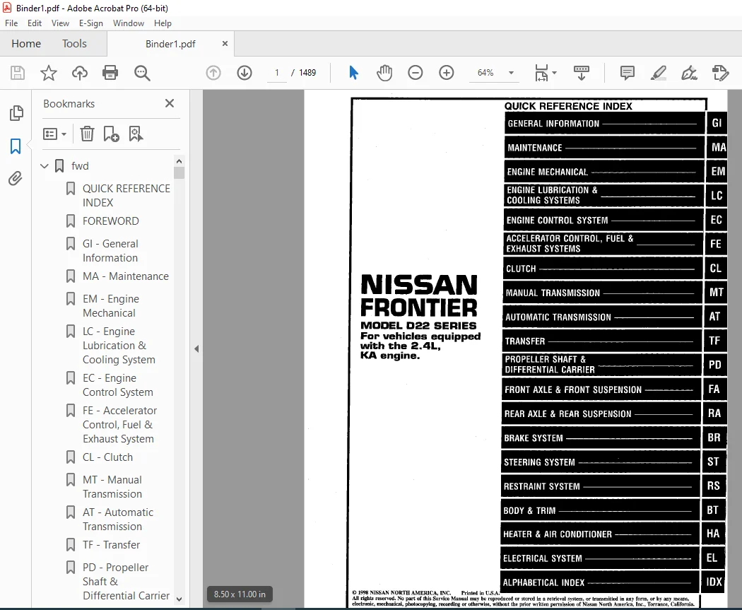
NISSAN FRONTIER D22 SERIES FOR THE VEHICLES EQIPPED WITH THE 2.4L, KA ENGINE
Instant PDF Download
Available immediately
Save to Your Device
Download & keep forever
Antivirus Scanned
100% virus-free
Trusted Worldwide
175,000+ customers
Description
1999 NISSAN FRONTIER D22 Series(2.4L KA Engine) Service Manual PDF DOWNLOAD
FILE DETAILS:
1999 NISSAN FRONTIER D22 Series(2.4L KA Engine) Service Manual PDF DOWNLOAD
Language : English
Pages : 1489
Downloadable : Yes
File Type : PDF
IMAGES PREVIEW OF THE MANUAL:
Questions? Email us: [email protected]
https://vimeo.com/851877971?share=copy
DESCRIPTION:
1999 NISSAN FRONTIER D22 Series(2.4L KA Engine) Service Manual PDF DOWNLOAD
FOREWORD
- This manual contains maintenance and repair procedure for the 1999 NISSAN FRONTIER FOR THE VEHICLES EQIPPED WITH THE 2.4L, KA ENGINE
- In order to assure your safety and the efficient functioning of the vehicle, this manual should be read thoroughly.
- It is especially important that the PRECAUTIONS in the GI section be completely understood before starting any repair task.
- All information in this manual is based on the latest product information at the time of publication. The right is reserved to make changes in specifications and methods at any time without notice.
IMPORTANT SAFETY NOTICE
- The proper performance of service is essential for both the safety of the technician and the efficient functioning of the vehicle.
- The service methods in this Service Manual are described in such a manner that the service may be performed safely and accurately.
- Service varies with the procedures used, the skills of the technician and the tools and parts available.
- Accordingly, anyone using service procedures, tools or parts which are not specifically recommended by NISSAN must first be completely satisfied that neither personal safety nor the vehicle’s safety will be jeopardized by the service method selected.
TABLE OF CONTENTS:
1999 NISSAN FRONTIER D22 Series(2.4L KA Engine) Service Manual PDF DOWNLOAD
NISSAN FRONTIER D22 SERIES FOR THE VEHICLES EQIPPED WITH THE 2.4L, KA ENGINE
fwd.......................................................................................................   1
	QUICK REFERENCE INDEX.................................................................................   1
	FOREWORD..............................................................................................   2
	GI - General Information..............................................................................   0
	MA - Maintenance......................................................................................   0
	EM - Engine Mechanical................................................................................   0
	LC - Engine Lubrication & Cooling System..............................................................   0
	EC - Engine Control System............................................................................   0
	FE - Accelerator Control, Fuel & Exhaust System.......................................................   0
	CL - Clutch...........................................................................................   0
	MT - Manual Transmission..............................................................................   0
	AT - Automatic Transmission...........................................................................   0
	TF - Transfer.........................................................................................   0
	PD - Propeller Shaft & Differential Carrier...........................................................   0
	FA - Front Axle & Front Suspension....................................................................   0
	RA - Rear Axle & Rear Suspension......................................................................   0
	BR - Brake System.....................................................................................   0
	ST - Steering System..................................................................................   0
	RS - Restraint System.................................................................................   0
	BT - Body & Trim......................................................................................   0
	HA  - Heating & Air Conditioner.......................................................................   0
	EL - Electrical System................................................................................   0
	IDX - Alphabetical Index..............................................................................   1
	Foldout...............................................................................................   0
	GST Mode 6 - Test Value & Test Limit .................................................................   3
at........................................................................................................   4
	QUICK REFERENCE INDEX.................................................................................   0
	Table of Contents.....................................................................................   4
	PRECAUTIONS AND PREPARATION...........................................................................   5
		Supplemental Restraint System (SRS) "AIR BAG".....................................................   5
		Precautions.......................................................................................   5
		Service Notice or Precautions.....................................................................   6
		Special Service Tools.............................................................................   7
	OVERALL SYSTEM........................................................................................   9
		Circuit Diagram...................................................................................   9
		Wiring DIagram....................................................................................  10
		Cross-Sectional View..............................................................................  12
		Hydraulic COntrol Circuits........................................................................  13
		Shift Mechanism...................................................................................  15
	TROUBLE DIAGNOSIS - Basic Inspection..................................................................  26
		Symptom Chart.....................................................................................  33
	TROUBLE DIAGNOSIS FOR DTC P1550.......................................................................  37
		Torque Converter Clutch Solenoid Valve............................................................  37
	TROUBLE DIAGNOSES.....................................................................................  39
		Component Inspection..............................................................................  39
	TROUBLE DIAGNOSES - A/T Shilft Lock System............................................................  42
		Description.......................................................................................  42
		Shift Lock System Electrical Parts Location.......................................................  42
		Wiring DIagram....................................................................................  43
		Diagnostic Procedure..............................................................................  44
		Shift Lock Rod....................................................................................  46
		Component Check...................................................................................  47
	ON-VEHICLE SERVICE....................................................................................  48
		Control Valve Assembly and Accumulators Removal...................................................  48
		Rear Oil Seal Replacement.........................................................................  48
		Parking Components Inspection.....................................................................  49
		Governor Valve....................................................................................  49
		Throttle Wire Adjustment..........................................................................  49
		Park/Neutral Postions (PNP) Switch Adjustment.....................................................  50
		Control Cable Adjustment..........................................................................  50
	REMOVAL AND INSTALLATION..............................................................................  51
		Removal...........................................................................................  52
		Installation......................................................................................  53
	MAJOR OVERHAUL........................................................................................  54
		Oil Channel.......................................................................................  56
		Locations of Needle Bearings, Thrust Washers and Snap of Rings....................................  57
	DISASSEMBLY...........................................................................................  58
	REPAIR FOR COMPONENT PARTS............................................................................  69
		Oil Pump..........................................................................................  69
		Control Valve Assembly............................................................................  73
		Control Valve Upper Body..........................................................................  78
		Control Valve Lower Body..........................................................................  82
		Governor Valve Assembly...........................................................................  84
		Parking Gear......................................................................................  84
		Reverse Clutch....................................................................................  85
		High Clutch.......................................................................................  89
		Forward and Overrun Clutches......................................................................  91
		Low & Reverse Brake...............................................................................  95
		Forward Clutch Drum Assembly......................................................................  98
		Rear Internal Gear and Forward Clutch Hub......................................................... 100
		Band Servo Piston Assembly........................................................................ 102
		Parking Pawl Components........................................................................... 106
	ASSEMBLY.............................................................................................. 108
		Assembly (1)...................................................................................... 108
		Adjustment........................................................................................ 116
		Assembly (2)...................................................................................... 118
	SERVICE DATA AND SPECIFICATIONS (SDS)................................................................. 125
br........................................................................................................ 129
	QUICK REFERENCE INDEX.................................................................................   0
	Table of Contents..................................................................................... 129
	PRECAUTIONS AND PREPARATION........................................................................... 131
		Supplemental Restraint System (SRS) "AIR BAG"..................................................... 131
		Precautions for Brake System...................................................................... 132
		Commercial Service Tools.......................................................................... 132
	NOISE, VIBRATION AND HARSHNESS (NVH) TROUBLESHOOTING.................................................. 133
		NVH Troubleshooting Chart......................................................................... 133
	ON-VEHICLE SERVICE.................................................................................... 134
		Checking Brake Fluid Level........................................................................ 134
		Checking Brake Line............................................................................... 134
		Changing Brake Fluid.............................................................................. 134
		Brake Burnishing Procedure........................................................................ 134
		Bleeding Brake System............................................................................. 135
	BRAKE HYDRAULIC LINE.................................................................................. 136
	CONTROL VALVE......................................................................................... 138
		Load Sensing Valve (2WD).......................................................................... 138
	BRAKE HYDRAULIC LINE/CONTROL VALVE.................................................................... 140
		Proportioning Valve (4WD)......................................................................... 140
	BRAKE PEDAL AND BRACKET............................................................................... 141
		Removal and Installation.......................................................................... 141
		Inspection........................................................................................ 142
		Adjustment........................................................................................ 142
	MASTER CYLINDER....................................................................................... 143
		Removal........................................................................................... 143
		Disassembly....................................................................................... 143
		Inspection........................................................................................ 144
		Assembly.......................................................................................... 144
		Installation...................................................................................... 145
	BRAKE BOOSTER......................................................................................... 146
		On-vehicle Service................................................................................ 146
		Removal........................................................................................... 146
		Inspection........................................................................................ 146
		Installation...................................................................................... 147
	VACUUM HOSE........................................................................................... 148
		Removal and Installation.......................................................................... 148
		Inspection........................................................................................ 148
	FRONT DISC BRAKE...................................................................................... 149
		Pad Replacement................................................................................... 149
		Removal........................................................................................... 150
		Disassembly....................................................................................... 151
		Inspection – Caliper.............................................................................. 151
		Inspection – Rotor................................................................................ 151
		Assembly.......................................................................................... 152
		Installation...................................................................................... 152
	REAR DRUM BRAKE....................................................................................... 153
		Removal........................................................................................... 154
		Inspection – Wheel Cylinder....................................................................... 155
		Wheel Cylinder Overhaul........................................................................... 155
		Inspection – Drum................................................................................. 155
		Inspection – Lining............................................................................... 155
		Installation...................................................................................... 155
	PARKING BRAKE CONTROL................................................................................. 157
		Removal and installation.......................................................................... 158
		Inspection........................................................................................ 158
		Adjustment........................................................................................ 158
	ABS - 2WD............................................................................................. 159
		REAR WHEEL ANTI-LOCK BRAKE SYSTEM................................................................. 159
			Purpose....................................................................................... 159
			Operation..................................................................................... 159
			ABS Hydraulic Circuit......................................................................... 159
			System Components............................................................................. 160
			System Description............................................................................ 160
			Removal and Installation...................................................................... 161
		TROUBLE DIAGNOSES................................................................................. 163
			How to Perform Trouble diagnoses for Quick and Accurate Repair................................ 163
			Preliminary Check............................................................................. 165
			Component Parts and Harness Connector Location................................................ 166
			Schematic..................................................................................... 168
			Wiring Diagram - ABS - ....................................................................... 169
			Self-diagnosis................................................................................ 171
			Main Power Supply and Ground Circuit Check.................................................... 174
		TROUBLE DIAGNOSES FOR SELF-DIAGNOSTIC ITEMS....................................................... 175
			Diagnostic Procedure 1........................................................................ 175
			Diagnostic Proceudre 2........................................................................ 175
			Diagnostic Procedure 3........................................................................ 176
			Diagnostic Procedure 4........................................................................ 177
			Diagnostic Procedure 5........................................................................ 177
			Diagnostic Procedure 6........................................................................ 177
			Diagnostic Procedure 7 (Warning lamp flashing 5).............................................. 178
		TROUBLE DIAGNOSES FOR SYMPTOMS.................................................................... 179
			Diagnostic Procedure 8 (ABS works frequently)................................................. 179
			Diagnostic Procedure 9 (Brake pedal stroke is large).......................................... 180
			Diagnostic Procedure 10 (Long stopping distance).............................................. 180
			Diagnostic Procedure 11 (ABS does not work.).................................................. 181
			Diagnostic Procedure 12 (Pedal vibration or noise)............................................ 181
			Electrical Components Inspection.............................................................. 182
	ABS - 4WD............................................................................................. 183
		ANTI-LOCK BRAKE SYSTEM............................................................................ 183
			Purpose....................................................................................... 183
			Operation..................................................................................... 183
			ABS Hydraulic Circuit......................................................................... 183
			System Components............................................................................. 184
			System Description............................................................................ 184
			Removal and Installation...................................................................... 186
		TROUBLE DIAGNOSES................................................................................. 189
			How to Perform Trouble Diagnoses for Quick and Accurate Repair................................ 189
			Preliminary Check............................................................................. 191
			Component Parts and Harness Connector Location................................................ 192
			Schematic..................................................................................... 193
			Wiring Diagram - ABS -........................................................................ 194
			Self-diagnosis................................................................................ 197
			CONSULT....................................................................................... 200
			CONSULT Inspection Procedure.................................................................. 201
			Ground Circuit Check.......................................................................... 206
		TROUBLE DIAGNOSES FOR SELF-DIAGNOSTIC ITEMS....................................................... 207
			Diagnostic Procedure 1 (Wheel sensor or rotor)................................................ 207
			Diagnostic Procedure 2 (ABS actuator solenoid valve and solenoid valve relay)................. 209
			Diagnostic Procedure 3 (Motor relay or motor)................................................. 211
			Diagnostic Procedure 4 (Low voltage).......................................................... 213
			Diagnostic Procedure 5 (G sensor)............................................................. 214
			Diagnostic Procedure 6 (Control unit)......................................................... 215
		TROUBLE DIAGNOSES FOR SYMPTOMS.................................................................... 216
			Diagnostic Procedure 7 (ABS works frequently.)................................................ 216
			Diagnostic Procedure 8 (Unexpected pedal action).............................................. 217
			Diagnostic Procedure 9 (Long stopping distance)............................................... 217
			Diagnostic Procedure 10 (ABS does not work.).................................................. 218
			Diagnostic Procedure 11 (Pedal vibration and noise)........................................... 218
			Diagnostic Procedure 12 (Warning lamp does not come on when ignition switch is turned ON.).... 219
			Diagnostic Procedure 13 (Warning lamp stays on when ignition switch is turned ON.)............ 221
			Electrical Components Inspection.............................................................. 223
	SERVICE DATA AND SPECIFICATIONS (SDS)................................................................. 224
		General Specifications............................................................................ 224
		Inspection and Adjustment......................................................................... 225
bt........................................................................................................ 226
	QUICK REFERENCE INDEX.................................................................................   0
	Table of Contents..................................................................................... 226
	PRECAUTIONS AND PREPARATION........................................................................... 227
		Service Notice.................................................................................... 227
		Supplemental Restraint System (SRS) "AIR BAG"..................................................... 227
	GENERAL SERVICING..................................................................................... 228
		Clip and Fastener................................................................................. 238
	BODY END.............................................................................................. 230
		Body Front End.................................................................................... 230
		Removal - Front bumper assembly................................................................... 230
		Body Rear End..................................................................................... 233
		Removal - Rear bumper assembly.................................................................... 233
	DOOR.................................................................................................. 235
		Front Door........................................................................................ 235
	INSTRUMENT PANEL...................................................................................... 236
		Removal - Instrument panel assembly............................................................... 236
	INTERIOR TRIM......................................................................................... 239
		Side and Floor Trim............................................................................... 239
		Removal - Body side trim.......................................................................... 239
		King cab model.................................................................................... 239
		Standard cab  model............................................................................... 239
		Door trim......................................................................................... 242
		Removal........................................................................................... 242
		Door trim (Formed type)........................................................................... 242
		Roof Trim......................................................................................... 245
		Removal - Headlining.............................................................................. 245
	EXTERIOR.............................................................................................. 247
		1 Hood front sealing rubber....................................................................... 248
		2 Cowl top seal and cowl top grille............................................................... 248
		3 Windshield side molding......................................................................... 248
		4  Windshield upper molding....................................................................... 248
		5 Sunroof weatherstrip and lid protector.......................................................... 248
		6 Drip weatherstrip............................................................................... 249
		7 Body side welt.................................................................................. 249
		8 Door weatherstrip............................................................................... 249
		9 Door outside molding............................................................................ 249
		10 Drafter duct................................................................................... 250
		11 Over fender.................................................................................... 250
		12 Rear combination lamp.......................................................................... 250
	SEAT.................................................................................................. 251
		Front Seat........................................................................................ 251
		Jump Seat- King Cab Model......................................................................... 254
	SUNROOF............................................................................................... 255
	WINDSHIELD AND WINDOWS................................................................................ 256
		Windshield........................................................................................ 257
		Side Window....................................................................................... 257
		Back Window....................................................................................... 258
		Rearview Mirror................................................................................... 259
	MIRROR................................................................................................ 260
		Door Mirror....................................................................................... 260
		Removal - Door mirror............................................................................. 260
	CAB AND REAR BODY..................................................................................... 261
		Body Mounting..................................................................................... 261
	BODY ALIGNMENT........................................................................................ 262
		Engine Compartmennt............................................................................... 263
		Measurement....................................................................................... 263
		Measurement Points................................................................................ 264
		Underbody......................................................................................... 265
		Measurement....................................................................................... 265
		2WD-4WD (Short wheelbase) models.................................................................. 265
		Measurement Points................................................................................ 266
		2WD-4WD (Short wheelbase) models.................................................................. 266
		Measurement....................................................................................... 267
		2WD-4WD (long wheelbase) models................................................................... 267
		Measurement Points................................................................................ 268
		2WD-4WD (Long wheelbase) models................................................................... 268
cl........................................................................................................ 269
	QUICK REFERENCE INDEX.................................................................................   0
	Table of Contents..................................................................................... 269
	PRECAUTIONS AND PREPARATION........................................................................... 270
		Precautions....................................................................................... 270
		Special Service Tools............................................................................. 270
		Commercial Service Tools.......................................................................... 270
	NOISE, VIBRATION AND HARSHNESS (NVH) TROUBLESHOOTING.................................................. 271
		NVH Troubleshooting Chart......................................................................... 271
	CLUTCH SYSTEM......................................................................................... 272
		Clutch Pedal...................................................................................... 273
	INSPECTION AND ADJUSTMENT............................................................................. 274
		Adjusting Clutch Pedal............................................................................ 274
		Air Bleeding Procedure............................................................................ 275
	HYDRAULIC CLUCTCH CONTROL............................................................................. 276
		Clutch Master Cylinder (With clutch damper)....................................................... 276
		Operating Cylinder................................................................................ 277
	CLUTCH RELEASE MECHANISM.............................................................................. 278
	CLUTCH DISC AND CLUTCH COVER.......................................................................... 281
		Clutch Disc....................................................................................... 281
		Clutch Cover and Flywheel......................................................................... 282
	SERVICE DATA AND SPECIFICATIONS (SDS)................................................................. 283
		General Specifications............................................................................ 283
			Clutch Control System......................................................................... 283
		Inspection and Adjustment......................................................................... 283
ec........................................................................................................ 284
	QUICK REFERENCE INDEX.................................................................................   0
	Table of Contents..................................................................................... 284
	DIAGNOSTIC TROUBLE CODE INDEX......................................................................... 287
		Alphabetical & P No. Index for DTC................................................................ 287
	PRECAUTIONS AND PREPARATION........................................................................... 289
		Special Service Tools............................................................................. 289
		Commercial Service Tools.......................................................................... 289
		Supplemental Restraint System (SRS) "AIR BAG"..................................................... 290
		Precautions for On Board Diagnostics (OBD) System of Engine....................................... 290
		Engine Fuel & Emission Control System............................................................. 291
		Precautions....................................................................................... 292
	ENGINE AND EMISSION CONTROL OVERALL SYSTEM............................................................ 294
		Circuit Diagram................................................................................... 294
		Engine Control Component Parts Location........................................................... 295
		System Diagram.................................................................................... 297
		Vacuum Hose Drawing............................................................................... 298
		System Chart...................................................................................... 297
	ENGINE AND EMISSION BASIC CONTROL SYSTEM DESCRIPTION.................................................. 300
		Multiport Fuel Injection (MFI) System............................................................. 300
		Distributor Ignition (DI) System.................................................................. 302
		Air Conditioning Cut Control...................................................................... 303
		Fuel Cut Control.................................................................................. 304
	EVAPORATIVE EMISSION SYSTEM........................................................................... 305
		Description....................................................................................... 305
		Inspection........................................................................................ 305
		Evaporative Emission Line Drawing................................................................. 308
	POSITIVE CRANKCASE VENTILATION........................................................................ 310
		Description....................................................................................... 310
		Inspection........................................................................................ 310
	BASIC SERVICE PROCEDURE............................................................................... 311
		Fuel Pressure Release............................................................................. 311
		Fuel Pressure Check............................................................................... 311
		Fuel Pressure Regulator Check..................................................................... 311
		Injector Removal and Installation................................................................. 312
		Fast Idle Cam (FIC)............................................................................... 313
		Idle Speed/Ignition Timing/Idle Mixture Ratio Adjustment.......................................... 314
	ON BOARD DIAGNOSTIC SYSTEM DESCRIPTION................................................................ 320
		Introduction...................................................................................... 320
		Two Trip Detection Logic.......................................................................... 320
		Emission-related Diagnostic Information........................................................... 321
		Malfunction Indicator Lamp (MIL).................................................................. 331
		OBD System Operation Chart........................................................................ 334
		CONSULT........................................................................................... 339
		Generic Scan Tool (GST)........................................................................... 350
	TROUBLE DIAGNOSIS - Introduction...................................................................... 352
		Introduction...................................................................................... 352
		Diagnostic Worksheet.............................................................................. 352
	TROUBLE DIAGNOSIS - Work Flow......................................................................... 354
		Work Flow......................................................................................... 354
		Description of Work Flow.......................................................................... 355
	TROUBLE DIAGNOSIS - Basic Inspection.................................................................. 356
		Basic Inspection.................................................................................. 356
	TROUBLE DIAGNOSIS - General Description............................................................... 362
		Diagnostic trouble Code (DTC) Inspection Priority Chart........................................... 362
		Fail-Safe Chart................................................................................... 363
		Symptom Matrix Chart.............................................................................. 364
		CONSULT Reference Value in Data Monitor Mode...................................................... 367
		Major Sensor Reference Graph in Data Monitor Mode................................................. 369
		ECM Terminals and Reference Value................................................................. 371
	TROUBLE DIAGNOSIS FOR INTERMITTENT INCIDENT........................................................... 380
		Description....................................................................................... 380
		Common I/I Report Situations...................................................................... 380
		Diagnostic Procedure.............................................................................. 380
	TROUBLE DIAGNOSIS FOR POWER SUPPLY.................................................................... 381
		Main Power Supply and Ground Circuit.............................................................. 381
	DTC P0100, Mass Air Flow Sensor (MAFS)................................................................ 386
	DTC P0105, Absolute Pressure Sensor................................................................... 397
	DTC P0110, Intake Air Temperature Sensor.............................................................. 402
	DTC P0115, Engine Coolant Temperature Sensor (ECTS) (Circuit)......................................... 408
	DTC P0120, Throttle Position Sensor................................................................... 413
	DTC P0125, Engine Coolant Temperature (ECT) Sensor.................................................... 427
	DTC P0130, Front Heated Oxygen Sensor (Circuit) (Front HO2S).......................................... 432
	DTC P0131, Front Heated Oxygen Sensor (Lean Shift Monitoring) (Front HO2S)............................ 438
	DTC P0132, Front Heated Oxygen Sensor (Rich Shift Monitoring) (Front HO2S)............................ 444
	DTC P0133, Front Heated Oxygen Sensor (Response Monitoring) (Front HO2S).............................. 450
	DTC P0134, Front Heated Oxygen Sensor (High Voltage) (Front HO2S)..................................... 458
	DTC P0135, Front Heated Oxygen Sensor Heater.......................................................... 464
	DTC P0137, Rear Heated Oxygen Sensor (Min.  Voltage Monitoring) (Rear HO2S)........................... 468
	DTC P0138, Rear Heated Oxygen Sensor (Max.  Voltage Monitoring) (Rear HO2S)........................... 475
	DTC P0139, Rear Heated Oxygen Sensor (Response Monitoring) (Rear HO2S)................................ 482
	DTC P0140, Rear Heated Oxygen Sensor (High Voltage) (Rear HO2S)....................................... 489
	DTC P0141, Rear Heated Oxygen Sensor Heater........................................................... 494
	DTC P0171, Fuel Injection System Function (Lean side)................................................. 498
	DTC P0172, Fuel Injection System Function (Rich side)................................................. 503
	DTC P0180, Tank Fuel Temperature Sensor............................................................... 508
	DTC P0300 - P0304, No. 4 - 1 Cylinder Misfire, Multiple Cylinder Misfire.............................. 512
	DTC P0325, Knock Sensor (KS).......................................................................... 517
	DTC P0335, Crankshaft Position Sensor (CKPS) (OBD).................................................... 521
	DTC P0340, Camshaft Position Sensor (CMPS)............................................................ 526
	DTC P0400, EGR Function (Close)....................................................................... 532
	DTC P0402, EGRC-BPT Valve Function.................................................................... 540
	DTC P0420, Three Way Catalyst Function................................................................ 545
	DTC P0440, Evaporative Emission (EVAP) Control System (Small Leak) (Negative Pressure)................ 550
	DTC P0443, Evaporative Emission (EVAP) Canister Purge Volume Control Solenoid Valve (Circuit)......... 560
	DTC P0446, Evaporative Emission (EVAP) Canister Vent Control Valve (Circuit).......................... 566
	DTC P0450, Evaporative Emission (EVAP) Control System Pressure Sensor................................. 571
	DTC P0500, Vehicle Speed Sensor (VSS)................................................................. 577
	DTC P0505, Idle Air Control Valve (IACV) - Auxiliary Air Control (AAC) Valve.......................... 582
	DTC P0510, Closed Throttle Position Switch............................................................ 588
	DTC P0605, Engine Control Module (ECM)................................................................ 594
	DTC P1105, Manifold Absolute Pressure (MAP)/Barometric Pressure (BARO) Switch Solenoid Valve.......... 596
	DTC P1148, Closed Loop Control........................................................................ 605
	DTC P1320, Ignition SIgnal............................................................................ 607
	DTC P1336, Crankshaft Position Sensor (CRPS) (OBD) (COG).............................................. 614
	DTC P1400, EGRC-Solenoid Valve........................................................................ 617
	DTC P1401, EGR Temperature Sensor..................................................................... 624
	DTC P1402, EGR Function (Open)........................................................................ 630
	DTC P1440, Evaporative Emission (EVAP) Control System (Small Leak) (Positive Pressure)................ 637
	DTC P1444, Evaporative Emission (EVAP) Canister Purge Volume Control Solenoid Valve................... 647
	DTC P1446, Evaporative Emission Emission (EVAP) Canister Vent Control Valve (Close)................... 655
	DTC P1447, Evaporative Emission (EVAP) Control System Purge Flow Monitoring........................... 660
	DTC P1448, Evaporative Emission (EVAP) Canister Vent Control Valve (Open)............................. 666
	DTC P1490, Vacuum Cut Valve Bypass Valve (Circuit).................................................... 671
	DTC P1491, Vacuum Cut Valve Bypass Valve.............................................................. 676
	DTC P1706, Park/Neutral Position (PNP) Switch......................................................... 681
	DTC P1775 Torque Converter Clutch Solenoid Valve (Circuit)............................................ 686
	DTC P1776 Torque Converter Clutch Solenoid Valve...................................................... 690
	TROUBLE DIAGNOSIS FOR OVERHEAT........................................................................ 694
		Overheat.......................................................................................... 694
	TROUBLE DIAGNOSIS FOR NON-DETECTABLE ITEMS............................................................ 697
		Injector.......................................................................................... 697
		Start Signal...................................................................................... 700
		Fuel Pump......................................................................................... 703
		Power Steering Oil Pressure Switch................................................................ 708
		IACV-FICD Solenoid Valve.......................................................................... 713
		MIL & Data Link Connectors........................................................................ 715
	SERVICE DATA AND SPECIFICATIONS (SDS)................................................................. 716
		General Specifications............................................................................ 716
		Inspection and Adjustment......................................................................... 716
el........................................................................................................ 718
	QUICK REFERENCE INDEX.................................................................................   0
	Table of Contents..................................................................................... 718
	PRECAUTIONS AND PREPARATION........................................................................... 721
		Supplemental Restraint System (SRS) "AIR BAG"..................................................... 721
	HARNESS CONNECTOR..................................................................................... 722
		Description....................................................................................... 722
	STANDARDIZED RELAY.................................................................................... 724
		Description....................................................................................... 724
	POWER SUPPLY ROUTING.................................................................................. 727
		Schematic......................................................................................... 727
		Wiring Diagram-POWER-............................................................................. 729
		Fuse.............................................................................................. 734
		Fusible Link...................................................................................... 734
		Circuit Breaker Inspection........................................................................ 734
	GROUND DISTRIBUTION................................................................................... 735
		Main Harness...................................................................................... 735
		Engine Room Harness............................................................................... 738
		Engine Control Harness............................................................................ 740
		Engine No. 2 Harness.............................................................................. 741
	BATTERY............................................................................................... 742
		How to Handle Battery............................................................................. 742
		Service Data and Specifiactions (SDS)............................................................. 745
	STARTING SYSTEM....................................................................................... 746
		System Description................................................................................ 746
		Wiring Diagram –START–............................................................................ 748
		Construction...................................................................................... 750
		Removal and Installation.......................................................................... 752
		Pinion/Clutch  Check.............................................................................. 752
		Service Data and Specifications (SDS)............................................................. 752
	CHARGING SYSTEM....................................................................................... 753
		System Description................................................................................ 753
		Wiring Diagram -CHARGE-........................................................................... 754
		Trouble Diagnoses................................................................................. 755
		Constuction....................................................................................... 756
		Removal and Installation.......................................................................... 757
		Service Data and Specifications (SDS)............................................................. 757
	COMBINATION SWITCH.................................................................................... 758
		Check............................................................................................. 758
		Replacement....................................................................................... 759
	STEERING SWITCH....................................................................................... 760
		Check............................................................................................. 760
	HEADLAMP.............................................................................................. 761
		System  Description (For USA)..................................................................... 761
		Wiring Diagram (For USA) -H/LAMP-................................................................. 762
		Trouble Diagnoses................................................................................. 763
		Bulb Replacment................................................................................... 764
		Aiming Adjustment................................................................................. 764
	HEADLAMP-Daytime Light System-........................................................................ 767
		System Description (For Canada)................................................................... 767
		Operation (For Canada)............................................................................ 768
		Schematic (For Canada)............................................................................ 769
		Wiring Diagram (For Canada) -DTRL-................................................................ 770
		Trouble Diagnoses (For Canada).................................................................... 773
		Bulb Replacement.................................................................................. 774
		Aiming Adjustment................................................................................. 774
	PARKING, LICENSE AND TAIL LAMPS....................................................................... 775
		Wiring Diagram -TAIL/L-........................................................................... 775
	STOP LAMP............................................................................................. 777
		Wiring Diagram -STOP/L-........................................................................... 777
	BACK-UP LAMP.......................................................................................... 778
		Wiring Diagram -BACK/L-........................................................................... 778
	FRONT FOG LAMP........................................................................................ 779
		System Description................................................................................ 779
		Wiring Diagram -F/FOG-............................................................................ 780
		Aiming Adjustment................................................................................. 781
		Removal and Installation.......................................................................... 782
		Bulb and Lens Replacement......................................................................... 782
	TURN SIGNAL AND HAZARD WARNING LAMPS.................................................................. 783
		System Description................................................................................ 783
		Wiring Diagram -TURN-............................................................................. 785
		Trouble Diagnoses................................................................................. 787
		Electrical Components Inspection.................................................................. 787
	ILLUMINATION.......................................................................................... 788
		System Description................................................................................ 788
		Wiring Diagram -ILL-.............................................................................. 789
	INTERIOR ROOM LAMP.................................................................................... 790
		Component Parts and Harness Connector Location.................................................... 790
		System Description................................................................................ 791
		Wiring Diagram-ROOM/L-............................................................................ 793
		Trouble Diagnoses (For model  with power door locks).............................................. 795
	SPOT LAMP............................................................................................. 797
		Wiring Diagram-INT/L-............................................................................. 797
	METER AND GAUGES...................................................................................... 798
		Component Parts and Harness Connector Location.................................................... 798
		System Description................................................................................ 799
		Unified Control Meter............................................................................. 799
		How To Change The Display For Odo/Trip Meter...................................................... 799
		Combination Meter................................................................................. 801
		With Tachometer................................................................................... 801
		Without Tachometer................................................................................ 802
		Wiring Diagram-METER-............................................................................. 803
		Meter/gauge Operation and Odo/Trip Meter.......................................................... 804
		Segment Check in Diagnoses Mode................................................................... 804
		Diagnosis Fuction................................................................................. 804
		How To Alternate Diagnosis Mode................................................................... 804
		Flexible Print Circuit (FPC)...................................................................... 805
		Disconnect........................................................................................ 805
		Connect........................................................................................... 805
		Trouble Diagnoses................................................................................. 806
		Preliminary Check................................................................................. 806
		Symptom Chart 1 (Malfunction is indicated in diagnosis mode)...................................... 807
		Symptom Chart 2 ( No malfunction is indicated in diagnosis mode).................................. 807
		Power Supply And Ground Circuit Check............................................................. 808
		Inspection/Vehicle Speed Sensor................................................................... 809
		Inspection/Engine Revolution Signal (Models with tachometer)...................................... 809
		Inspection/Fuel Tank Gauge........................................................................ 810
		Inspection/Thermal Transmitter.................................................................... 810
		Electrical Components Inspection.................................................................. 811
		Meter/Gauge Resistance Check...................................................................... 811
		Fuel tank Gauge Unit Check........................................................................ 811
		Thermal Transmitter Check......................................................................... 812
		Vehicle Speed Sensor Signal Check................................................................. 812
	WARNING LAMPS......................................................................................... 813
		System Description................................................................................ 813
		Schematic......................................................................................... 815
		Wiring Diagram -WARN-............................................................................. 816
		Electrical Components Inspection.................................................................. 819
	A/T INDICATOR......................................................................................... 820
		Wiring Diagram-AT/IND-............................................................................ 820
	WARNING CHIME......................................................................................... 821
		Component Parts and Harness Connector Location.................................................... 821
		System Description................................................................................ 822
		Wiring diagram-CHIME-............................................................................. 824
		Trouble Diagnoses................................................................................. 826
		Electrical Components Inspection.................................................................. 832
	FRONT WIPER AND WASHER................................................................................ 833
		System Description................................................................................ 833
		Wiring Diagram-WIPER-............................................................................. 835
		Trouble Diagnoses (With intermittent wipers)...................................................... 837
		Removal and Installation.......................................................................... 839
		Washer Nozzle Adjustment.......................................................................... 840
		Washer Tube Layout................................................................................ 840
	HORN.................................................................................................. 841
		Wiring diagram-HORN-.............................................................................. 841
	CIGARETTE LIGHTER..................................................................................... 842
		Wiring Diagram -CIGAR-............................................................................ 842
	AUDIO................................................................................................. 843
		System Description................................................................................ 843
		Base Audio System................................................................................. 843
		Premium Audio System.............................................................................. 843
		Wiring Diagram-AUDIO-............................................................................. 844
		Trouble Diagnoses................................................................................. 847
		Inspection........................................................................................ 848
	AUDIO ANTENNA......................................................................................... 849
		Fixed Antenna Rod Replacement..................................................................... 849
		Removal........................................................................................... 849
		Installation...................................................................................... 849
	POWER DOOR MIRROR..................................................................................... 850
		Wiring Diagram-MIRROR-............................................................................ 850
	AUTOMATIC SPEED CONTRL DEVICE (ASCD).................................................................. 851
		Component Parts and Harness Connector Location.................................................... 851
		System Description................................................................................ 852
		Schematic......................................................................................... 854
		Wiring Diagram-ASCD-.............................................................................. 855
		Fail-Safe System Description...................................................................... 859
		Fail-Safe System Check............................................................................ 860
		Trouble Diagnoses................................................................................. 861
		ASCD Wire Adjustment.............................................................................. 869
		Electrical Components Inspection.................................................................. 870
	POWER WINDOW.......................................................................................... 871
		System Description................................................................................ 871
		Wiring diagram-WINDOW-............................................................................ 873
		Trouble Diagnoses................................................................................. 875
	POWER DOOR LOCKS...................................................................................... 876
		Component Parts and Harness Connector Location.................................................... 876
		System Description................................................................................ 877
		Schematic......................................................................................... 879
		Wiring Diagram-D/LOCK-............................................................................ 880
		Trouble Diagnoses................................................................................. 883
	MULTI-REMOTE CONTROL SYSTEM........................................................................... 891
		Component Parts and Harness Connector Location.................................................... 891
		System Description................................................................................ 892
		Schematic......................................................................................... 894
		Wiring Diagram-MULTI-............................................................................. 895
		Trouble Diagnoses................................................................................. 898
		Electrical Components Inspection.................................................................. 904
		ID Code Entry Procedure........................................................................... 905
	THEFT WARNING SYSTEM.................................................................................. 906
		Component Parts and Harness Connector Location.................................................... 906
		System Description................................................................................ 908
		Schematic......................................................................................... 911
		Wiring Diagram-THEFT-............................................................................. 912
		Trouble Diagnoses................................................................................. 915
	SMART ENTRANCE CONTROL UNIT........................................................................... 926
		Description....................................................................................... 926
		Input/Output Operation Signal..................................................................... 927
		Schematic......................................................................................... 929
	LOCATION OF ELECTRICAL UNITS.......................................................................... 931
		Engine Compartment................................................................................ 931
		Passenger Compartment............................................................................. 932
	HARNESS LAYOUT........................................................................................ 934
		Outline........................................................................................... 934
		How to Read Harness Layout........................................................................ 935
		Main Harness...................................................................................... 937
		Engine Room Harness............................................................................... 939
		Engine Control Harness............................................................................ 943
		Engine No. 2 Harness.............................................................................. 945
		Chassis and Tail Harness.......................................................................... 947
		Room Lamp Harness................................................................................. 948
		Door Harness...................................................................................... 949
		Air Bag Harness................................................................................... 950
	BULB SPECIFICATIONS................................................................................... 951
		Headlamp.......................................................................................... 951
		Exterior Lamp..................................................................................... 951
		Interior Lamp..................................................................................... 951
	WIRING DIAGRAM CODES (CELL CODES)..................................................................... 952
em........................................................................................................ 953
	QUICK REFERENCE INDEX.................................................................................   0
	Table of Contents..................................................................................... 953
	PRECAUTIONS AND PREPARATION........................................................................... 954
		Supplemental Restraint System (SRS) "AIR BAG"..................................................... 954
		Parts Requiring Angular  Tightening............................................................... 954
		Liquid Gasket Application Procedure............................................................... 954
		Special Service Tools............................................................................. 956
		Commercial Service Tools.......................................................................... 959
	NOISE, VIBRATION AND HARSHNESS (NVH) TROUBLESHOOTING.................................................. 960
		NVH Troubleshooting Chart - Engine Noise.......................................................... 961
	OUTER COMPONENTS PARTS................................................................................ 962
	COMPRESSION PRESSURE.................................................................................. 965
		Measurement of Compression Pressure............................................................... 965
	OIL PAN............................................................................................... 966
		Removal........................................................................................... 966
		Installation...................................................................................... 967
	TIMING CHAIN.......................................................................................... 968
		Removal........................................................................................... 970
			Upper Timing Chain............................................................................ 970
			Lower Timing Chain............................................................................ 972
		Inspection........................................................................................ 973
		Installation...................................................................................... 973
			Lower Timing Chain............................................................................ 973
			Upper Timing Chain............................................................................ 974
	OIL SEAL REPLACEMENT.................................................................................. 977
		Valve Oil Seal.................................................................................... 977
		Oil Seal Installing Direction..................................................................... 977
		Front Oil Seal.................................................................................... 977
		Rear Oil Seal..................................................................................... 978
	CYLINDER HEAD......................................................................................... 980
		Removal and Installation.......................................................................... 981
		Disassembly....................................................................................... 981
		Inspection........................................................................................ 982
		Assembly.......................................................................................... 987
		Valve Clearance................................................................................... 987
			Checking...................................................................................... 987
			Adjusting..................................................................................... 988
	ENGINE REMOVAL........................................................................................ 990
		Removal........................................................................................... 991
		Installation...................................................................................... 992
	CYLINDER BLOCK........................................................................................ 993
		Disassembly....................................................................................... 994
		Inspection........................................................................................ 994
		Assembly..........................................................................................1000
	SERVICE DATA AND SPECIFICATION (SDS)..................................................................1004
		General Specifications............................................................................1004
			Compression Pressure..........................................................................1004
		Inspection and Adjustment.........................................................................1004
			Cylinder Head.................................................................................1004
			Valve.........................................................................................1004
			Camshaft and Camshaft Bearing.................................................................1008
			Piston, Piston Ring and Piston Pin............................................................1009
			Connecting Rod................................................................................1009
fa........................................................................................................1012
	QUICK REFERENCE INDEX.................................................................................   0
	Table of Contents.....................................................................................1012
	PRECAUTIONS AND PREPARATION...........................................................................1013
		Precautions.......................................................................................1013
		Special Service Tools.............................................................................1013
		Commercial Service Tools..........................................................................1014
	NOISE, VIBRATION AND NOISE (NVH) TROUBLESHOOTING......................................................1015
		NVH Troubleshooting...............................................................................1015
	FRONT SUSPENSION SYSTEM...............................................................................1016
		2WD...............................................................................................1016
		4WD...............................................................................................1017
	ON-VEHICLE SERVICE....................................................................................1018
		Front Axle and Front Suspension...................................................................1018
		Front Wheel Bearing...............................................................................1018
		Front Wheel Alignment.............................................................................1020
		Drive Shaft.......................................................................................1024
	FRONT AXLE............................................................................................1025
		Manual-lock Free-running Hub -- 4WD --............................................................1027
		Auto-lock Free-running Hub -- 4WD --..............................................................1028
		Wheel Hub and Rotor Disc..........................................................................1028
		Knuckle Spindle...................................................................................1030
		Drive Shaft -- 4WD --.............................................................................1033
	FRONT SUSPENSION......................................................................................1038
		Shock Absorber....................................................................................1040
		Torsion Bar Spring................................................................................1040
		Stabilizer Bar....................................................................................1042
		Upper Link........................................................................................1043
		Tension Rod.......................................................................................1044
		Lower Link........................................................................................1045
		Upper Ball Joint and Lower Ball Joint.............................................................1046
	SERVICE DATA AND SPECIFICATIONS (SDS).................................................................1047
		General Specifications............................................................................1047
		Inspection and Adjustment.........................................................................1047
fe........................................................................................................1051
	QUICK REFERENCE INDEX.................................................................................   0
	Table of Contents.....................................................................................1051
	PREPARATION...........................................................................................1052
		Special Service Tool..............................................................................1052
	ACCELERATOR CONTROL SYSTEM............................................................................1053
		Adjusting Accelerator Wire........................................................................1053
	FUEL SYSTEM...........................................................................................1054
		Fuel Tank.........................................................................................1054
		Fuel Pump and Gauge...............................................................................1057
	EXHAUST SYSTEM........................................................................................1058
foldout...................................................................................................1061
	QUICK REFERENCE INDEX.................................................................................   0
gi........................................................................................................1067
	QUICK REFERENCE GUIDE.................................................................................   0
	Table of Contents.....................................................................................1067
	PRECAUTIONS AND PREPARATION...........................................................................1068
		Supplemental Restraint System (SRS) "AIR BAG".....................................................1068
		General Precautions...............................................................................1069
		Precautions for Multiport Fuel Injection System or Engine Control System..........................1071
		Precautions for Three Way Catalyst................................................................1071
		Precautions for Engine Oils.......................................................................1071
		Precautions for Fuel..............................................................................1072
		Precautions for Air Conditioning..................................................................1072
	HOW TO USE THIS MANUAL................................................................................1073
	HOW TO READ WIRING DIAGRAM............................................................................1075
		Sample/Wiring Diagram - EXAMPL -..................................................................1075
		Description.......................................................................................1077
	HOW TO CHECK TERMINAL.................................................................................1083
		Connector and Terminal Pin Kit....................................................................1083
		How to Probe Connectors...........................................................................1083
		How to Check Enlarged Contact Spring of Terminal..................................................1084
		Waterproof Connector Inspection...................................................................1085
		Terminal Lock Inspection..........................................................................1085
	HOW TO PERFORM EFFICIENT DIAGNOSIS FOR AN ELECTRICAL INCIDENT.........................................1086
		Work Flow.........................................................................................1086
		Incident Simulation Tests.........................................................................1087
		Circuit Inspection................................................................................1089
		Control Unit Circuit Test.........................................................................1095
	HOW TO FOLLOW FLOW CHART IN TROUBLE DIAGNOSES.........................................................1096
		How to Follow This Flow Chart.....................................................................1097
	CONSULT CHECKING SYSTEM...............................................................................1099
		Function and System Application...................................................................1099
		Lithium Battery Replacement.......................................................................1099
		Checking Equipment................................................................................1099
		Loading Procedures................................................................................1100
		CONSULT Data Link Connector (DLC) Circuit.........................................................1100
	IDENTIFICATION INFORMATION............................................................................1101
		Model Variation...................................................................................1101
		Identification Number.............................................................................1103
		Dimensions........................................................................................1105
		Wheels and Tires..................................................................................1105
	LIFTING POINTS AND TOW TRUCK TOWING...................................................................1106
		Pantograph Jack...................................................................................1106
		Garage Jack and Safety Stand......................................................................1107
		2-pole Lift.......................................................................................1108
		Tow Truck Towing..................................................................................1109
			2-WHEEL DRIVE MODELS..........................................................................1109
			4-WHEEL DRIVE MODELS..........................................................................1110
		Towing Point......................................................................................1111
			Vehicle Recovery (Freeing a stuck vehicle)....................................................1111
	TIGHTENING TORQUE OF STANDARD BOLTS...................................................................1112
	SAE J1930 TERMINOLOGY LIST............................................................................1113
ha........................................................................................................1117
	QUICK REFERENCE INDEX.................................................................................   0
	Table of Contents.....................................................................................1117
	PRECAUTIONS AND PREPARATION...........................................................................1118
		Supplemental Restraint System (SRS) "AIR BAG".....................................................1118
		Precuations for Working with R-134a...............................................................1118
			Contaminated Refrigerant......................................................................1119
		General Refrigerant Precautions...................................................................1119
		Precautions for Refrigerant Connection............................................................1120
		Precautions for Servicing Compressor..............................................................1123
		R-134a Service Tools and Equipment................................................................1124
		Special Service Tools.............................................................................1126
		Commercial Service Tools..........................................................................1126
		Precautions for Service Equipment.................................................................1127
	DESCRIPTION...........................................................................................1129
		Refrigeration Cycle...............................................................................1129
		Control Operation.................................................................................1130
		Component Layout..................................................................................1131
		Discharge Air Flow................................................................................1132
		Component Location................................................................................1133
		Circuit Diagram...................................................................................1135
		Wiring Diagram - HEATER-..........................................................................1136
		Wiring Diagram - A/C-.............................................................................1137
		Operational Check.................................................................................1139
	TROUBLE DIAGNOSES.....................................................................................1141
		How to Perform Trouble Diagnoses for Quick and Accurate Repair....................................1141
		Blower Motor Circuit..............................................................................1142
		Air Outlet........................................................................................1146
		Intake Door.......................................................................................1148
		Magnet Clutch Circuit.............................................................................1149
		Trouble Diagnosis Procedure For Insufficient Cooling..............................................1155
		Performance Test Diagnoses........................................................................1157
		Performance Chart.................................................................................1159
		Trouble Diagnoses for Abnormal Pressure...........................................................1160
		Trouble Diagnosis for Insufficient Heating .......................................................1163
		Troulble Diagnosis for Noise......................................................................1165
	SERVICE PROCEDURES....................................................................................1166
		Refrigerant Lines.................................................................................1166
		Checking Refrigerant Leaks........................................................................1167
		R-134a Service Procedure..........................................................................1170
		Compressor Lubricant Quantity.....................................................................1172
		Compressor Mounting...............................................................................1174
		Belt Tension......................................................................................1174
		Fast Idle Control Device (FICD)...................................................................1174
		Condenser.........................................................................................1174
		Compressor........................................................................................1175
		Compressor Clutch.................................................................................1175
		Thermal Protector.................................................................................1178
		Heater Unit (Heater Core).........................................................................1179
		Cooling Unit (A/C Evaporator).....................................................................1180
		Blower Case and Motor.............................................................................1181
		Fan Lever and Illumination Bulbs..................................................................1182
	SERVICE DATA AND SPECIFICATIONS (SDS).................................................................1183
		General Specifications............................................................................1183
		Inspection and Adjustment.........................................................................1183
idx.......................................................................................................1184
	QUICK REFERENCE INDEX.................................................................................   0
lc........................................................................................................1193
	QUICK REFERENCE INDEX.................................................................................   0
	Table of Contents.....................................................................................1193
	PRECAUTIONS AND PREPARATION...........................................................................1194
		Supplemental Restraint System (SRS) "AIR BAG".....................................................1194
		Liquid Gasket Application Procedure...............................................................1194
		Special Service Tools.............................................................................1195
	ENGINE LUBRICATION SYSTEM.............................................................................1196
		Lubrication Circuit...............................................................................1196
		Oil Pressure Check................................................................................1197
		Oil Pump..........................................................................................1197
	ENGINE COOLING SYSTEM.................................................................................1196
		Cooling Circuit...................................................................................1199
		System Check......................................................................................1199
		Water Pump........................................................................................1201
			Removal.......................................................................................1201
		Thermostat........................................................................................1202
		Radiator..........................................................................................1203
		Cooling Fan (Crankshaft driven)...................................................................1204
			Inspection....................................................................................1204
				Refilling engine coolant..................................................................1204
		Radiator (Aluminum type)..........................................................................1205
			Inspection....................................................................................1205
		Overheating Cause Analysis........................................................................1206
	SERVICE DATA AND SPECIFICATIONS (SDS).................................................................1207
		Engine Lubrication System.........................................................................1207
		Engine Cooling System.............................................................................1207
ma........................................................................................................1208
	QUICK  REFERENCE INDEX................................................................................   0
	Table of Contents.....................................................................................1208
	PRECAUTIONS AND PREPARATION...........................................................................1209
		Supplemental Restraint System (SRS) "AIR BAG".....................................................1209
		Special Service Tool..............................................................................1209
		Commercial Service Tool...........................................................................1209
	GENERAL MAINTENANCE...................................................................................1210
	PERIODIC MAINTENANCE..................................................................................1212
		Schedule 1........................................................................................1213
		Schedule 2........................................................................................1214
	RECOMMENDED FLUIDS AND LUBRICANTS.....................................................................1215
		Fluids and Lubricants.............................................................................1215
		SAE Viscosity Number..............................................................................1216
		Antifreeze Coolant Mixture Ratio..................................................................1216
	ENGINE MAINTENANCE....................................................................................1217
		Checking Drive Belts..............................................................................1217
		Changing Engine Coolant...........................................................................1219
			-DRAINING ENGINE COOLANT-.....................................................................1219
			-REFILLING ENGINE COOLANT-....................................................................1219
			-FLUSHING COOLING SYSTEM-.....................................................................1220
		Checking Fuel Lines...............................................................................1221
		Changing Fuel Filter..............................................................................1221
		Changing Air Cleaner Filter.......................................................................1221
		Changing Engine Oil...............................................................................1222
		Changing Oil Filter...............................................................................1222
		Changing Spark Plugs..............................................................................1223
		Checking EVAP Vapor Lines.........................................................................1224
	CHASSIS AND BODY MAINTENANCE..........................................................................1225
		Checking Exhaust System...........................................................................1225
		Checking Clutch Fluid Level and Leaks.............................................................1225
		Checking M/T Oil..................................................................................1225
		Changing M/T Oil..................................................................................1225
		Checking Water Entry - For 4WD models.............................................................1225
		Checking A/T Fluid................................................................................1225
		Changing A/T Fluid................................................................................1226
		Checking Transfer Fluid...........................................................................1226
		Changing Transfer Fluid...........................................................................1227
		Checking Propeller Shaft..........................................................................1227
		Checking Differential Gear Oil....................................................................1227
		Changing Differential Gear Oil....................................................................1228
		Balancing Wheels..................................................................................1228
		Tire Rotation.....................................................................................1228
		Checking Brake Fluid Level and Leaks..............................................................1229
		Checking Brake System.............................................................................1229
		Checking Disc Brake...............................................................................1229
		Checkiing Drum Brake..............................................................................1229
		Checking Steering Gear Oil Level and Leaks........................................................1230
		Lubricating Hood Latches, Locks and Hinges........................................................1231
		Checking Seat Belts, Buckles, Retractors, Anchors and Adjusters...................................1232
	SERVICE DATA AND SPECIFICATIONS (SDS).................................................................1233
		Engine Maintenance................................................................................1233
		Chassis and Body Maintenance......................................................................1233
mt........................................................................................................1234
	QUICK REFERENCE INDEX.................................................................................   0
	Table of Contents.....................................................................................1234
	PREPARATION...........................................................................................1235
		Special Service Tools.............................................................................1235
		Commercial Service Tools..........................................................................1236
	NOISE, VIBRATION AND HARSHNESS (NVH) TROUBLESHOOTING..................................................1237
		NVH Troubleshooting Chart.........................................................................1237
	DESCRIPTION...........................................................................................1238
		Cross-sectional View -- 2WD Model --..............................................................1238
		Cross-sectional View -- 4WD Model --..............................................................1239
	ON-VEHICLE SERVICE....................................................................................1240
		Replacing Rear Oil Seal -- 2WD Model --...........................................................1240
		Position Switch Check.............................................................................1240
	REMOVAL AND INSTALLATION..............................................................................1241
	MAJOR OVERHAUL........................................................................................1244
		Case Components...................................................................................1244
		Gear Components -- 2WD Model --...................................................................1245
		Gear Components -- 4WD Model --...................................................................1246
		Shift Control Components..........................................................................1247
	DISASSEMBLY...........................................................................................1248
		Case Components...................................................................................1248
		Shift Control Components..........................................................................1248
		Gear Components...................................................................................1249
	INSPECTION............................................................................................1252
		Shift Control Components..........................................................................1252
		Gear Components...................................................................................1252
			Gears And Shafts..............................................................................1252
			Synchronizers.................................................................................1252
			Bearings......................................................................................1253
	ASSEMBLY..............................................................................................1254
		Gear Components...................................................................................1254
		Shift Control Components..........................................................................1260
		Case Components...................................................................................1261
	SERVICE DATA AND SPECIFICATIONS (SDS).................................................................1264
		General Specifications............................................................................1264
		Inspection and Adjustment.........................................................................1265
pd........................................................................................................1267
	QUICK REFERENCE INDEX.................................................................................   0
	Table of Contents.....................................................................................1267
	PREPARATION...........................................................................................1269
		Special Service Tools.............................................................................1269
	NOISE, VIBRATION AND HARSHNESS (NVH) TROUBLESHOOTING..................................................1273
		NVH Troubleshooting Chart.........................................................................1273
	PROPELLER SHAFT.......................................................................................1274
		PROPELLER SHAFT...................................................................................1274
			On-vehicle Service............................................................................1276
			Removal and Installation......................................................................1276
			Inspection....................................................................................1276
			Disassembly...................................................................................1277
			Assembly......................................................................................1278
	FINAL DRIVE...........................................................................................1280
		ON-VEHICLE SERVICE................................................................................1280
			Front Oil Seal Replacement (Front final drive: Model R180A)...................................1280
			Rear Cover Gasket Replacement (Rear final drive: Model C200)..................................1280
		REMOVAL AND INSTALLATION (Front final drive)......................................................1281
			Removal.......................................................................................1281
			Installation..................................................................................1281
		REMOVAL AND INSTALLATION (Rear final drive).......................................................1282
			Removal.......................................................................................1282
			Installation..................................................................................1282
	FRONT FINAL DRIVE, R180A..............................................................................1283
		FRONT FINAL DRIVE.................................................................................1283
		DISASSEMBLY.......................................................................................1284
			Pre-inspection................................................................................1284
			Final Drive Housing...........................................................................1284
			Differential Case.............................................................................1286
			Extension Tube and Differential Side Shaft....................................................1287
		INSPECTION........................................................................................1289
			Ring Gear and Drive Pinion....................................................................1289
			Differential Case Assembly....................................................................1289
			Bearing.......................................................................................1289
		ADJUSTMENT........................................................................................1290
			Side Bearing Preload..........................................................................1290
			Pinion Gear Height and Pinion Bearing Preload.................................................1291
			Tooth Contact.................................................................................1295
		ASSEMBLY..........................................................................................1296
			Extension Tube and Differential Side Shaft....................................................1296
			Differential Case.............................................................................1296
			Final Drive Housing...........................................................................1297
	REAR FINAL DRIVE, H190A...............................................................................1301
		REAR FINAL DRIVE..................................................................................1301
		DISASSEMBLY.......................................................................................1302
			Pre-inspection................................................................................1302
			Differential Carrier..........................................................................1302
			Differential Case.............................................................................1304
		INSPECTION........................................................................................1306
			Ring Gear and Drive Pinion....................................................................1306
			Differential Case Assembly....................................................................1306
			Bearing.......................................................................................1306
		ADJUSTMENT........................................................................................1307
			Side Bearing Preload..........................................................................1307
			Pinion Gear Height............................................................................1308
			Tooth Contact.................................................................................1312
		ASSEMBLY..........................................................................................1313
			Differential Case.............................................................................1313
			Differential Carrier..........................................................................1314
	REAR FINAL DRIVE, 2WD MODELS, C200....................................................................1318
		REAR FINAL DRIVE..................................................................................1318
			2WD models....................................................................................1318
			4WD models....................................................................................1319
		DISASSEMBLY.......................................................................................1320
			Pre-inspection................................................................................1320
			Differential Carrier..........................................................................1320
			Differential Case.............................................................................1322
		INSPECTION........................................................................................1324
			Ring Gear and Drive Pinion....................................................................1324
			Differential Case Assembly....................................................................1324
			Bearing.......................................................................................1324
		ADJUSTMENT........................................................................................1325
			Side Bearing Preload..........................................................................1325
			Pinion Gear Height............................................................................1326
			Tooth Contact.................................................................................1330
		ASSEMBLY..........................................................................................1331
			Differential Case.............................................................................1331
			Differential Carrier..........................................................................1332
	SERVICE DATA AND SPECIFICATIONS (SDS).................................................................1336
		Propeller Shaft...................................................................................1336
		Final Drive.......................................................................................1337
			General Specifications........................................................................1337
			Inspection And Adjustment (R180A).............................................................1338
			Inspection And Adjustment (H190A).............................................................1339
			Inspection And Adjustment (C200)..............................................................1340
ra........................................................................................................1341
	QUICK REFERENCE INDEX.................................................................................   0
	Table of Contents.....................................................................................1341
	PRECAUTIONS AND PREPARATION...........................................................................1342
		Precautions.......................................................................................1342
		Special Service Tools.............................................................................1342
		Commercial Service Tools..........................................................................1343
	NOISE, VIBRATION AND HARSHNESS (NVH) TROUBLESHOOTING..................................................1344
		NVH Troubleshooting Chart.........................................................................1344
	REAR SUSPENSION SYSTEM................................................................................1345
		2WD models........................................................................................1345
		4WD models........................................................................................1345
	ON-VEHICLE SERVICE....................................................................................1346
		Rear Axle and Rear Suspension Parts...............................................................1346
		Rear Wheel Bearing................................................................................1346
	REAR AXLE.............................................................................................1347
		Components........................................................................................1347
		Removal...........................................................................................1348
		Inspection........................................................................................1350
			Axle Shaft....................................................................................1350
			Wheel Bearing.................................................................................1350
			Axle Case.....................................................................................1350
		Installation -- 2WD models........................................................................1350
		Installation -- 4WD models........................................................................1352
	REAR SUSPENSION.......................................................................................1354
		2WD models........................................................................................1354
		4WD models........................................................................................1354
		Shock Absorber....................................................................................1355
			Removal And Installation......................................................................1355
			Inspection....................................................................................1355
		Leaf Spring.......................................................................................1355
			Removal And Installation......................................................................1355
			Inspection....................................................................................1356
			Installation..................................................................................1356
	SERVICE DATA AND SPECIFICATIONS (SDS).................................................................1357
		General Specifications............................................................................1357
		Inspection and Adjustment.........................................................................1357
rs........................................................................................................1358
	QUICK REFERENCE INDEX.................................................................................   0
	Table of Contents.....................................................................................1358
	PRECAUTIONS AND PREPARATION...........................................................................1359
		Supplemental Restraint System (SRS) "AIR BAG".....................................................1359
	SEAT BELTS............................................................................................1360
		Front Seat Belt...................................................................................1361
		Rear Seat Belt....................................................................................1362
		Seat Belt Inspection..............................................................................1363
	SUPPLEMENTAL RESTRAINT SYSTEM (SRS)...................................................................1366
		Precautions for SRS "AIR BAG" Service.............................................................1366
		Special Service Tools.............................................................................1367
		Description.......................................................................................1368
		Passenger air bag deactivation switch.............................................................1368
		SRS Component Parts Location......................................................................1369
		Maintenance Items.................................................................................1370
		Diagnosis Sensor Unit and Crash Zone Sensor.......................................................1371
			Removal And Installation......................................................................1371
				Air bag diagnosis sensor unit.............................................................1371
				Crash zone sensor (4WD models)............................................................1371
		Driver Air Bag Module and Spiral Cable............................................................1372
		Passenger Air Bag Module..........................................................................1376
		Passenger Air Bag Deactivation Switch.............................................................1378
		Passenger Air Bag Deactivation Switch Lock Cylinder...............................................1378
		Passenger Air Bag Deactivation Switch Indicator...................................................1379
		Disposal of Air Bag Module........................................................................1380
	TROUBLE DIAGNOSES – Supplemental Restraint System (SRS)...............................................1384
		Trouble Diagnosis Introduction....................................................................1384
		How to Perform Trouble diagnoses for Quick and Accurate Repair....................................1387
		Schematic.........................................................................................1388
		Wiring Diagram –SRS–..............................................................................1389
		Passenger Air Bag Deactivation Switch Indicator Operation Check...................................1391
		SRS Operation Check...............................................................................1392
		Trouble Diagnoses with CONSULT....................................................................1393
		Trouble Diagnoses without CONSULT.................................................................1402
		Trouble Diagnoses: "AIR BAG" Warning Lamp Does Not Turn Off.......................................1406
		Trouble Diagnoses: "AIR BAG" Warning Lamp Does Not Turn On........................................1407
		Trouble Diagnoses: SRS Does Not Enter Diagnosis Mode Using Door Switch............................1408
	COLLISION DIAGNOSIS...................................................................................1409
st........................................................................................................1412
	QUICK REFERENCE INDEX.................................................................................   0
	Table of Contents.....................................................................................1412
	PRECAUTIONS AND PREPARATION...........................................................................1414
		Supplemental Restraint System (SRS) "AIR BAG".....................................................1414
		Precautions for Steering System...................................................................1414
		Special Service Tools.............................................................................1415
	NOISE, VIBRATION AND HARSHNESS (NVH) TROUBLESHOOTING..................................................1417
		NVH Troubleshooting...............................................................................1417
	ON-VEHICLE SERVICE....................................................................................1418
		Steering System...................................................................................1418
		Checking and Adjusting Drive Belts (For power steering)...........................................1418
		Checking Fluid Level (For power steering).........................................................1418
		Checking Fluid Leakage (For power steering).......................................................1419
		Bleeding Hydraulic System (For power steering)....................................................1419
		Checking Steering Wheel Turning Force (For power steering)........................................1420
		Checking Steering Wheel Play......................................................................1420
		Checking Neutral Position on Steering Wheel ......................................................1421
			Checking......................................................................................1421
		Checking Front Wheel Turning Angle................................................................1421
		Checking Hydraulic System (For power steering)....................................................1422
	STEERING WHEEL AND STEERING COLUMN....................................................................1423
		Steering Wheel....................................................................................1423
			Removal And Installation......................................................................1423
		Steering Column...................................................................................1424
			Removal.......................................................................................1424
			Installation..................................................................................1424
		Disassembly and Assembly..........................................................................1425
			Tilt mechanism................................................................................1426
		Inspection........................................................................................1426
	MANUAL STEERING GEAR (Model: VB66K)...................................................................1427
		Removal and Installation..........................................................................1427
		Disassembly.......................................................................................1428
		Assembly and Adjustment...........................................................................1428
			Worm Gear Bearing Preload.....................................................................1428
			Sector Shaft End Play.........................................................................1430
			Steering Gear Preload and Backlash............................................................1430
		Inspection........................................................................................1431
			Sector Shaft..................................................................................1431
			Steering Worm Assembly........................................................................1432
			Bearing.......................................................................................1432
			Oil Seals.....................................................................................1432
	POWER STEERING SYSTEM (Model: PB48S)..................................................................1433
		Description.......................................................................................1433
	POWER STEERING GEAR (Model: PB48S)....................................................................1433
		Removal and Installation..........................................................................1434
			Steering Gear.................................................................................1434
		Power Steering Gear Component.....................................................................1434
		Pre-disassembly Inspection and Adjustment.........................................................1435
			Turning Torque Measurement....................................................................1435
		Disassembly.......................................................................................1435
			Adjusting Screw Lock Nut O-Ring...............................................................1436
			Sector Shaft Oil Seal.........................................................................1436
			Rear Housing O-Ring...........................................................................1437
			Rear Cover O-Ring and Oil Seal................................................................1437
		Assembly..........................................................................................1438
			Adjusting Screw Lock Nut O-Ring...............................................................1438
			Sector Shaft Oil Seal.........................................................................1438
			Sector Shaft End Play.........................................................................1439
			Rear Cover O-Ring and Oil Seal................................................................1439
			Rear Housing O-Ring...........................................................................1439
			Sector Shaft..................................................................................1440
	POWER STEERING SYSTEM (Model: PB59K)..................................................................1441
		Removal and Installation..........................................................................1442
			Steering Gear.................................................................................1442
		Power Steering Gear Component.....................................................................1442
		Pre-disassembly Inspection and Adjustment.........................................................1443
			Turning Torque Measurement....................................................................1443
		Disassembly.......................................................................................1444
		Assembly..........................................................................................1445
	POWER STEERING OIL PUMP...............................................................................1448
		Disassembly and Assembly..........................................................................1448
		Pre-disassembly Inspection........................................................................1448
		Inspection........................................................................................1449
			Pulley and Pulley Shaft.......................................................................1449
		Disassembly.......................................................................................1449
		Assembly..........................................................................................1450
	STEERING LINKAGE......................................................................................1451
		Removal and Installation..........................................................................1451
		Disassembly.......................................................................................1452
			Idler Arm Assembly............................................................................1452
			Cross Rod and Tie-Rod.........................................................................1452
		Inspection........................................................................................1453
			Ball Joint and Swivel Joint...................................................................1453
			Idler Arm Assembly............................................................................1453
			Cross Rod and Tie-Rod.........................................................................1453
			Fixing Location...............................................................................1453
	SERVICE DATA AND SPECIFICATIONS (SDS).................................................................1454
		General Specifications............................................................................1454
		Inspection and Adjustment.........................................................................1454
			Steering Column Length........................................................................1454
			Manual Steering Gear (Model: VB66K)...........................................................1455
			Steering Linkage .............................................................................1455
			Power Steering System (Model: PB48S)..........................................................1455
			Power Steering System (Model: PB59K)..........................................................1456
tf........................................................................................................1457
	QUICK REFERENCE INDEX.................................................................................   0
	Table of Contents.....................................................................................1457
	PREPARATION...........................................................................................1458
		Special Service Tools.............................................................................1458
		Commercial Service Tools..........................................................................1459
	NOISE, VIBRATION AND HARSHNESS (NVH) TROUBLESHOOTING..................................................1460
		NVH Troubleshooting Chart.........................................................................1460
			Transfer......................................................................................1460
	DESCRIPTION...........................................................................................1461
		Cross-sectional View..............................................................................1461
	ON-VEHICLE SERVICE....................................................................................1462
		Replacing Oil Seal................................................................................1462
			Center Case Oil Seal..........................................................................1462
			Shift Shaft Oil Seal..........................................................................1462
			Rear Oil Seal.................................................................................1463
	REMOVAL AND INSTALLATION..............................................................................1464
	TRANSFER GEAR CONTROL.................................................................................1465
	MAJOR OVERHAUL........................................................................................1466
		Case Components...................................................................................1466
		Gear Components...................................................................................1467
		Shift Control Components..........................................................................1468
	DISASSEMBLY...........................................................................................1469
	REPAIR FOR COMPONENTS PARTS...........................................................................1474
		Mainshaft.........................................................................................1474
		Front Drive Shaft.................................................................................1476
		Counter Gear......................................................................................1477
		Main Gear.........................................................................................1477
		Front Case........................................................................................1479
			Shift Shaft Oil Seal..........................................................................1479
		Front Case Cover..................................................................................1479
			Cover Oil Seal................................................................................1479
		Bearing Retainer..................................................................................1480
			Oil Catcher...................................................................................1480
		Rear Case.........................................................................................1480
			Rear Oil Seal.................................................................................1480
			Air Breather..................................................................................1480
		Shift Control Components..........................................................................1481
	ASSEMBLY..............................................................................................1482
	SERVICE DATA AND SPECIFICATIONS (SDS).................................................................1489
		General Specifications............................................................................1489
		Inspection and Adjustment.........................................................................1489
PLEASE NOTE:
- This is the same manual used by the dealers to diagnose and troubleshoot your vehicle
- You will be directed to the download page as soon as the purchase is completed. The whole payment and downloading process will take anywhere between 2-5 minutes
- Need any other service / repair / parts manual, please feel free to contact [email protected] . We still have 50,000 manuals unlisted
G.P