Trusted Business
Verified & Licensed
Virus Free Files
100% Safe Downloads
Secure Payment
SSL Protected
Instant Delivery
Available Immediately
1999 NISSAN MAXIMA A32 Series Service Manual PDF DOWNLOAD
$24.95
1999 NISSAN MAXIMA A32 Series Service Manual PDF DOWNLOAD
Instant PDF Download
Available immediately
Save to Your Device
Download & keep forever
Antivirus Scanned
100% virus-free
Trusted Worldwide
175,000+ customers
Description
1999 NISSAN MAXIMA A32 Series Service Manual PDF DOWNLOAD
FILE DETAILS:
1999 NISSAN MAXIMA A32 Series Service Manual PDF DOWNLOAD
Language : English
Pages : 1809
Downloadable :Yes
File Type : PDF
IMAGES PREVIEW OF THE MANUAL:
Customer Support: [email protected]
https://vimeo.com/852069514?share=copy
TABLE OF CONTENTS:
1999 NISSAN MAXIMA A32 Series Service Manual PDF DOWNLOAD
fwd 1
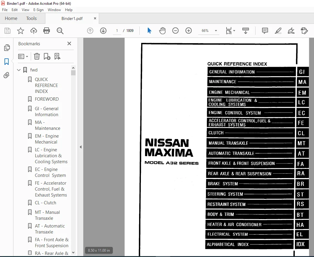
QUICK REFERENCE INDEX 1
FOREWORD 2
GI – General Information 0
MA – Maintenance 0
EM – Engine Mechanical 0
LC – Engine Lubrication & Cooling Systems 0
EC – Engine Control System 0
FE – Accelerator Control, Fuel & Exhaust Systems 0
CL – Clutch 0
MT – Manual Transaxle 0
AT – Automatic Transaxle 0
FA – Front Axle & Front Suspension 0
RA – Rear Axle & Rear Suspension 0
BR – Brake System 0
ST – Steering System 0
RS – Restraint System 0
BT – Body & trim 0
HA – Heater & Air Conditioner 0
EL – Electrical System 0
IDX – Alphabetical Index 1
Foldout 0
Comment Sheet 3
Quick Reference Chart 4
GST Mode 6 – Test Value & Test Limit – CAL Models 5
GST Mode 6 – Test Value & Test Limit – FED Models 6
AT 7
QUICK REFERENCE INDEX 0
TABLE OF CONTENTS 7
DIAGNOSTIC TROUBLE CODE INDEX 9
Alphabetical & P No Index for DTC 9
PRECAUTIONS AND PREPARATION 10
Supplemental Restaint System (SRS) “AIR BAG” and “SEAT BELT PRE-TENSIONER” 10
Precautions for On Board Diagnostic (OBD) System of A/T and Engine 10
Precautions 11
Service Notice or Precautions 12
Special Service Tools 14
Commercial Service Tools 17
OVERALL SYSTEM 18
A/T Electrical Parts Location 18
Circuit Diagram for Quick Pinpoint Check 19
Wiring Diagram – AT – 20
Cross-sectional View 26
Hydraulic Control Circuit 27
Shift Mechanism 28
Control System 37
Control Mechanism 39
Control Valve 44
ON BOARD DIAGNOSTIC SYSTEM DESCRIPTION 45
Introduction 45
OBD-II Function for A/T System 45
One or Two Trip Detection Logic of OBD-II 45
OBD-II Diagnostic Trouble Code (DTC) 45
Malfunction Indicator Lamp (MIL) 49
CONSULT 49
Diagnostic Procedure without CONSULT 56
TROUBLE DIAGNOSIS- Introduction 60
Introduction 60
Diagnostic Worksheet 61
Work Flow 64
TROUBLE DIAGNOSIS-Basic Inspection 65
A/T Fuid Check 65
Stall Test 65
Line Pressure Test 68
Road Test 69
TROUBLE DIAGNOSIS – General Description 80
Symptom Chart 80
TCM Terminals and Referance Value 83
TROUBLE DIAGNOSIS FOR POWER SUPPLY 86
Main Power Supply and Ground Circuit 86
DTC P0705, Park/Neutral Position (PNP) Switch 87
DTC P0710, A/T Fluid Temperature Sensor 91
DTC P0720, Vehicle Speed Sensor- A/T (Revolution sensor) 95
DTC P0725, Engine Speed Signal 98
DTC P0731, A/T 1st Gear Function 101
DTC P0732, A/T 2nd Gear Function 106
DTC P0733, A/T 3rd Gear Function 111
DTC P0734, A/T 4th Gear Function 116
DTC P0740, Torque Converter Clutch Solenoid Valve 124
DTC P0744, A/T TCC S/V Function (Lock-up) 128
DTC P0745, Line Pressure Solenoid Valve 135
DTC P0750, Shift Solenoid Valve A 139
DTC P0755, Shift Solenoid Valve B 143
DTC P1705, Throttle Position Sensor 147
DTC P1760, Overrun Clutch Solenoid Valve 153
TROUBLE DIAGNOSIS FOR BATT/FLUID TEMP SEN 157
A/T Fluid Temperature Sensor Circuit and TCM Power Source 157
TROUBLE DIAGNOSIS FOR VHCL SPEED SEN MTR 161
Vehicle Speed Sensor MTR 161
TROUBLE DIAGNOSIS FOR CONTROL UNIT (RAM), CONTROL UNIT (ROM) 164
TCM (Transmission Control Module) 164
TROUBLE DIAGNOSIS FOR SYMPTOMS 166
1 O/D OFF Indicator Lamp Does Not Come On 166
2 Engine Cannot Be Started In “P” and “N” Position 167
3 In “P” Position, Vehicle Moves Forward Or Backward When Pushed 167
4 In “N” Position, Vehicles Moves 168
5 Large Shock “N” “R” Position 169
6 Vehicle Does Not Creep Backward In “R” Position 170
7 Vehicle Does Not Creep Forward In “D”, “2” Or “1” Position 171
8 Vehicle Cannot Be Started from D1 172
9 A/T Does Not Shift: d1 D2 Or Does Not Kickdown D4 D2 173
10 A/T Does Not Shift: D2 D3 174
11 A/T Does Not Shift: D3 D4 175
12 A/T Does Not Perform Lock-up 176
13 A/T Does Not Hold Lock-up Condition 177
14 Lock-up is Not Released 177
15 Engine Speed Does Not Return To Idle (Light Braking D4 D3) 178
16 Vehicle Does Not Start From D1 179
17 A/T Does Not Shift: D4 D3, When Overdrive Control Switch “On” “OFF” 179
18 A/T Does Not Shift: D3 22, When Selector Lever “D” “2” Position 180
19 A/T Does Not Shift 22 1, When Selector Lever “2” “1” Position 180
20 Vehicle Does Not Decelerate By Engine Brake 181
21 TCM Self-dianosis Doe Not Activate ( Park/Neutral Position, Overdrive Control and Throttle Position Switch Circuit Checks 181
TROUBLE DIAGNOSES – A/T SHIFT LOCK SYSTEM 187
Description 187
Shift Lock System Electrical Parts Location 187
Wiring Diagram – Shift – 188
Diagnostic Procedure 189
Key Interlock Cable 191
Component Check 192
ON-VEHICLE SERVICE 194
Control Valve Assembly and Accumulator 194
Revolution Sensor Replacement 195
Park/Neutral Position Switch Adjustment 195
Control Cable Adjustment 196
Differential Side Oil Seal Replacement 196
REMOVAL AND INSTALLATION 197
Removal 197
Installation 198
MAJOR OVERHAUL 200
Locations of Adjusting Shims, Needle Bearings, Thrust Washers and Snap Rings 203
Oil Channel 204
DISASSEMBLY 205
REPAIR FOR COMPONENT PARTS 219
Manual Shaft 219
Oil Pump 221
Control Valve Assembly 225
Control Valve Upper Body 233
Control Valve Lower Body 237
Reverse Clutch 239
High Clutch 242
Forward Clutch and Overrun Clutch 246
Low & Reverse Brake 252
Rear Internal Gear, Forward Clutch Hub and Overrun Clutch Hub 254
Output Shaft, Idler Gear, Reduction Pinion Gear and Bearing Retainer 258
Band Servo Piston Assembly 262
Final Drive 268
ASSEMBLY 273
Assembly 1 273
Adjustment 1 273
Assembly 2 278
Adjustment 2 284
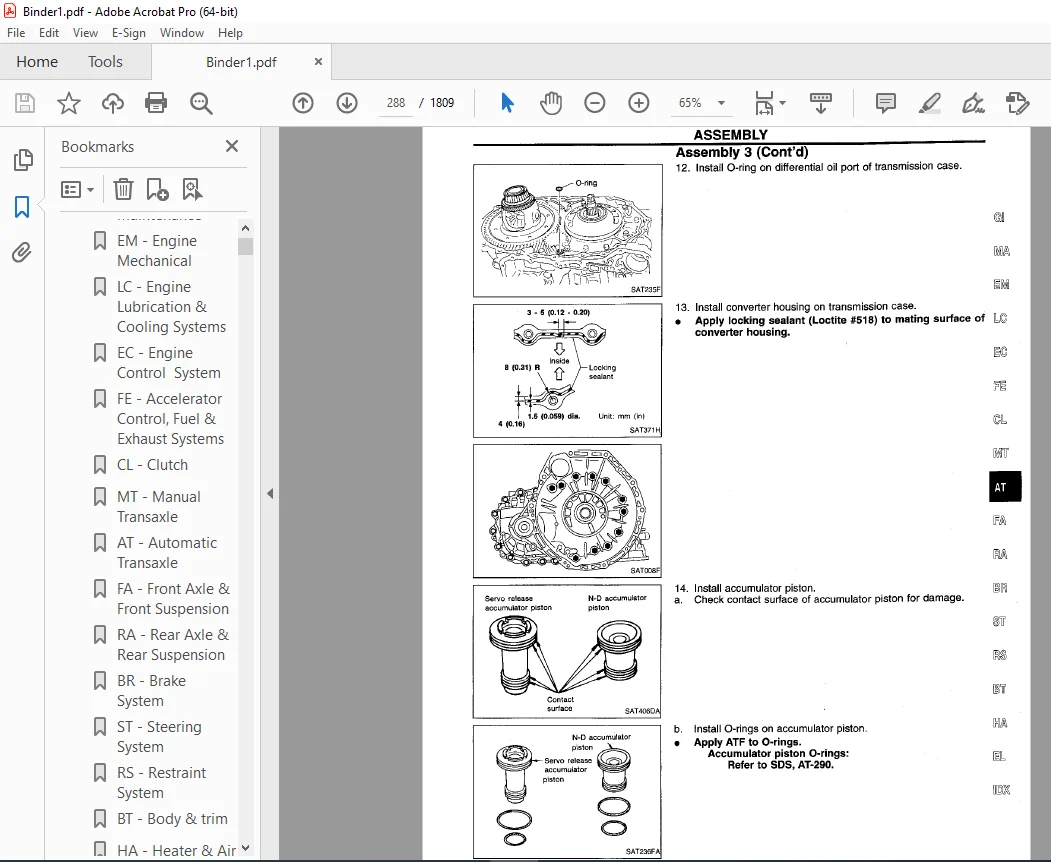
Assembly 3 286
SERVICE DATA AND SPECIFICATIONS (SDS) 292
General Specifications 292
Specifications and Adjustments 292
BR 299
QUICK REFERENCE INDEX 0
TABLE OF CONTENTS 299
PRECAUTIONS AND PREPARATION 301
Supplemental Restraint System (SRS) “AIR BAG” and “SEAT BELT PRE-TENSIONER” 301
Precautions for Brake System 301
Commercial Service Tools 302
NOISE, VIBRATION AND HARSHNESS (NVH) TROUBLESHOOTING 303
NVH Troubleshooting Chart 303
ON-VEHICLE SERVICE 304
Checking Brake Fluid Level 304
Checking Brake Line 304
Changing Brake Fluid 304
Brake Burnishing Procedure 304
Bleeding Brake System 305
BRAKE HYDRAULIC LINE /CONTROL VALVE 306
Brake Hydraulic Line 306
Dual Proportioning Valve 307
BRAKE PEDAL AND BRACKET 308
Removal and Installation 308
Inspection 308
Adjustment 308
MASTER CYLINDER 309
Removal 309
Disassembly 309
Inspection 310
Assembly 310
Installation 310
BRAKE BOOSTER/VACUUM HOSE 311
Brake Booster 311
Vacuum Hose 312
FRONT DISC BRAKE 313
Pad Replacement 313
Component 314
Removal 314
Disassembly 314
Inspection – Caliper 315
Inspection – Rotor 315
Assembly 316
Installation 316
REAR DISC BRAKE 317
Pad Replacement 317
Components 319
Removal 320
Disassembly 320
Inspection – Caliper 321
Inspection – Rotor 322
Assembly 322
Installation 323
PARKING BRAKE CONTROL 325
Removal and Installation 325
Inspection 326
Adjustment 326
ANTI-LOCK BRAKE SYSTEM (ABS) AND TRACTION CONTROL SYSTEM (TCS) 327
Purpose 327
ABS (Anti-Lock Brake System) Operation 327
ABS Hydraulic Circuit 327
TCS (Traction Control System) Operation 328
System Components 328
System Description 328
Removal and Installation 330
TROUBLE DIAGNOSES 332
How to Perform Trouble Diagnoses for Quick and Accurate Repair 332
Preliminary Check 333
Component Parts and Harness Connector Location 334
Schematic 335
Wiring Diagram -ABS/TCS 336
Self-diagnosis 340
CONSULT 343
CONSULT Inspection Procedure 344
Ground Circuit Check 351
TROUBLE DIAGNOSES FOR SELF-DIAGNOSTIC ITEMS 352
Diagnostic Procedure 1 (ENGINE CHECK SIGNAL – Engine system) 352
Diagnostic Procedure 2 (ENGINE SPEED SIG – Engine speed signal) 353
Diagnostic Procedure 3 (LAN SIGNAL 1 – LAN monitoring) 354
Diagnostic Procedure 4 (LAN SIGNAL 2– LAN communication start procedures incomplete) 355
Diagnostic Procedure 5 (LAN CIRCUITS 1, LAN CIRCUITS 2 – LAN communication system failure) 355
Diagnostic Procedure 6 (LAN SIGNAL 3 – Continued reception after LAN communication starts) 356
Diagnostic Procedure 7 (ABS actuator solenoid valve) 357
Diagnostic Procedure 8 (Wheel sensor or rotor) 359
Diagnostic Procedure 9 (ABS MOTOR – Motor relay or motor) 361
Diagnostic Procedure 10 (ABS ACTUATOR RELAY – Solenoid valve relay) 364
Diagnostic Procedure 11 (BATTERY VOLTAGE – Low or high voltage) 366
Diagnostic Procedure 12 (Control unit) 367
TROUBLE DIAGNOSES FOR SYMPTOMS 368
Diagnostic Procedure 13 (Peadal vibration and noise) 368
Diagnostic Procedure 14 (Long stopping distance) 369
Diagnostic Procedure 15 (Unexplained pedal action) 369
Diagnostic Procedure 16 (ABS does not work) 370
Diagnostic Procedure 17 (ABS works frequently) 370
Diagnostic Procedure 18 (SLIP indicator lamp does not on when ignition switch is turned on) 371
Diagnostic Procedure 19 (TCS OFF indicator lamp does not come on when ignition switch is turned on) 372
Diagnostic Procedure 20 (ABS warning lamp does not come on when ignition switch is turned on) 373
Diagnostic Procedure 21 (ABS warning lamp stays on continuously) 374
Diagnostic Procedure 22 (TCS OFF switch is inoperative) 377
Diagnostic Procedure 23 (poor acceleration) 378
SERVICE DATA AND SPECIFICATIONS (SDS) 379
General Specifications 379
Inspection and Adjustment 379
BT 380
QUICK REFERENCE INDEX 0
TABLE OF CONTENTS 380
PRECAUTIONS 381
Precaution 381
Supplemental Restraint System (SRS) “AIR BAG” and “SEAT BELT PRE-TENSIONER” 381
GENERAL SERVICING 382
Clip and Fastener 382
BODY END 385
Body Front End 385
Body Rear End and Operner 388
DOOR 390
Front Door 390
Rear Door 391
INSTRUMENT PANEL 392
INTERIOR TRIM 395
Side and Floor Trim 395
Door Trim 398
Roof Trim 399
Trunk Room Trim 400
EXTERIOR 401
SEAT 406
Front Seat 406
Heated Seat 410
Rear Seat 411
SUNROOF 412
Trouble Diagnoses 416
WINDSHIELD AND WINDOWS 420
Windshield and Rear Window 421
MIRROR 422
Door Mirror 422
BODY ALIGNMENT 423
Engine Compartment 423
Underbody 425
CL 427
QUICK REFERENCE INDEX 0
TABLE OF CONTENTS 427
PRECAUTIONS AND PREPARATION 428
Precautions 428
Special Service Tools 428
Commercial Service Tools 428
NOISE, VIBRATION AND HARSHNESS (NVH) TROUBLESHOOTING 429
NVH Troubleshooting Chart 429
CLUTCH SYSTEM – Hydraulic Type 430
INSPECTION AND ADJUSTMENT 431
Adjusting Clutch Pedal 431
Bleeding Procedure 432
HYDRAULIC CLUTCH CONTROL 433
Clutch Master Cylinder 433
Operating Cylinder 434
CLUTCH RELEASE MECHANISM 435
CLUTCH DISC AND CLUTCH COVER 436
Clutch Disc 436
Clutch Cover and Flywheel 437
SERVICE DATA AND SPECIFICATIONS (SDS) 438
General Specifications 438
Inspection and Adjustment 438
EC 439
QUICK REFERENCE INDEX 0
TABLE OF CONTENTS 439
DIAGNOSTIC TROUBLE CODE INDEX 442
Alphabetical & P No Index for DTC 442
PRECAUTIONS AND PREPARATION 446
Special Service Tool 446
Commercial Service Tools 446
Supplemental Restraint System (SRS) “AIR BAG” and “SEAT BELT PRE-TENTIONER” 447
Precautions for On Board Diagnostic (OBD) System of Engine and A/T 447
Engine Fuel & Emission Control System 448
Precautions 449
ENGINE AND EMISSION CONTROL OVERALL SYSTEM 451
Circuit Diagram 451
System Diagram 452
Engine Control Component Parts Location 454
Vacuum Hose Drawing 458
System Chart 460
ENGINE AND EMISSION BASIC CONTROL SYSTEM DESCRIPTION 461
Multiport Fuel Injection (MFI) System 461
Electronic Ignition (EI) System 463
Air Conditioning Cut Control 464
Fuel Cut Control (at no load & high engine speed) 465
EVAPORATIVE EMISSION SYSTEM 466
Description 466
Inspection 466
Evaporative Emission Line Drawing 469
On Board Refueling Vapor Recovery (ORVR) 471
POSITIVE CRANKCASE VENTILATION 476
Description 476
Inspection 476
BASIC SERVICE PROCEDURE 477
Fuel Pressure Release 477
Fuel Pressure Check 477
Injector Removal and Installation 478
Fast Idle Cam (FIC) Inspection and Adjustment 479
Direct Ignition System – How to Check Idle Speed and Ignition Timing 480
Idle Speed/Ignition Timing/Idle Mixture Ratio Adjustment 482
ON BOARD DIAGNOSTIC SYSTEM DESCRIPTION 490
Introduction 490
Two Trip Detection Logic 490
Emission-related Diagnostic Information 491
Malfunction Indicator Lamp (MIL) 504
OBD System Operation Chart 508
CONSULT 513
Generic Scan Tool (GST) 526
TROUBLE DIAGNOSIS – General Description 528
Introduction 528
Diagnostic Worksheet 528
Work Flow 530
Description for Work Flow 531
Basic Inspection 532
Diagnostic Trouble Code (DTC) Inspection Priority Chart 538
Priority Chart 538
Fail-Safe Chart 539
Symptom Matrix Chart 540
CONSULT Reference Value in Data Monitor Mode 543
Major Sensor Reference Graph in Data Monitor Mode 546
ECM Terminals and Reference Value 548
TROUBLE DIAGNOSIS FOR INTERMITTENT INCIDENT 556
Description 556
Common I/I Report Situations 556
Diagnostic Procedure 556
TROUBLE DIAGNOSIS FOR POWER SUPPLY 557
Main Power Supply and Ground Circuit 557
DTC P0100 Mass Air Flow Sensor (MAFS) 562
DTC P0105 Absolute Pressure Sensor 570
DTC P0110 Intake Air Temperature Sensor 579
DTC P0115 Engine Coolant Temperature Sensor (ECTS) 585
DTC P0120 Throttle Position Sensor 590
DTC P0125 Engine Coolant Temperature Sensor (ECTS) 601
DTC P0130 (-B1), P0150 (-B2), Front Heated Oxygen Sensor (Front HO2S) 606
DTC P0131 (-B1), P0151 -B2), Front Heated Oxygen Sensor (Lean Shift Monitoring) (Front HO2S) 614
DTC P0132 (-B1), P0152 (-B2), Front Heated Oxygen Sensor (Rich Shift Monitoring) (Front HO2S) 620
DTC P0133 (-B1), P0153 (-B2), Front Heated Oxygen Sensor (Response Monitoring) (Front HO2S) 626
DTC P0134 (-B1), P0154 (-B2), Front Heated Oxygen Sensor (High Voltage) (Front HO2S) 636
DTC P0135 (-B1), P0155 (-B2), Front Heated Oxygen Sensor Heater 644
DTC P0137 (-B1), P0157 (-B2) FOR CALIFORNIA, Rear Heated Oxygen Sensor (Min Voltage Monitoring) (Rear HO2S) 650
DTC P0138 (-B1), P0158 (-B2), FOR CALIFORNIA, Rear Heated Oxygen Sensor (Max Voltage Monitoring) (Rear HO2S 659
DTC P0139 (-B1), P0159 (-2), FOR CALIFORNIA, Rear Heated Oxygen Sensor (Response Monitoring) (Rear HO2S) 667
DTC P0140 (-B1), P0160 (-2), FOR CALIFORNIA, Rear Heated Oxygen Sensor (High Voltage) (Rear HO2S) 675
DTC P0137 EXCEPT FOR CALIFORNIA, Rear Heated Oxygen Sensor Heater (Min Voltage Monitoring) (Rear HO2S) 682
DTC P0138 EXCEPT FOR CALIFORNIA, Rear Heated Oxygen Sensor (Max Voltage Monitoring) (Rear HO2S) 689
DTC P0139 EXCEPT FOR CALIFORNIA, Rear Heated Oxygen Sensor (Response Monitoring) (Rear HO2S) 696
DTC P0140 EXCEPT FOR CALIFORNIA, Rear Heated Oxygen Sensor (High Voltage) (Rear HO2S) 703
DTC P0141 (-B1), P0161 (-B2) FOR CALIFORNIA – Rear Heated Oxygen Sensor Heaters 708
DTC P0141 EXCEPT FOR CALIFORNIA – Rear Heated Oxygen Sensor Heaters 714
DTC P0171 (-B1), P0174 (-B2) Fuel Injection System Function 719
DTC P0172 (-B1), P0175 (-B2) Fuel Injection System Function 725
DTC P0180 Tank Fuel Temperature Sensor 731
DTC P0306 – P0300, No 6 – 1 Cylinder Misfire, Multiple Cylinder Misfire 735
DTC P0325 Knock Sensor (KS) 740
DTC P0335 Crankshaft Position Sensor (CKPS) (POS) 744
DTC P0340 Camshaft Position Sensor (CMPS) (PHASE) 751
DTC P0400 EGR Function (Close) 756
DTC P0403 EGR Volume Control Valve (Circuit) 765
DTC P0420 (-B1), P0430 (-B2) FOR CALIFORNIA – Three Way Catalyst Function 771
DTC P0420 (-B1), EXCEPT FOR CALIFORNIA – Three Way Catalyst Function 774
DTC P0440 Evaporative Emission (EVAP) Control System (Small Leak) (Negative Pressure) 778
DTC P0443 Evaporative Emission (EVAP) Canister Purge Volume Control Solenoid Valve (Circuit) 788
DTC P0446 Evaporative Emission (EVAP) Canister Vent Control Valve (Circuit) 794
DTC P0450 Evaporative Emission (EVAP) Control System Pressure Sensor 799
DTC P0500 Vehicle Speed Sensor (VSS) 805
DTC P0505 Idle Air Control Valve (IACV) – Auxiliary Air Control (AAC) Valve 809
DTC P0510 Closed Throttle Position Switch 815
DTC P0600, P1605 – A/T Communication Line (PO600) and A/T Diagnostic Communication Line (P1605) 821
DTC P0605 Engine Control Module (ECM) 824
DTC P1105 Manifold Absolute Pressure (MAP)/Barometric Pressure (BARO) Switch Solenoid Valve 826
DTC P1130 Swirl Control Valve Control Solenoid Valve (Only for california) 835
DTC P1148 (-B1), P1168 (-B2) Closed Loop Control 848
DTC P1165 Swirl Control Valve Control Vacuum Check Switch (Only for California) 850
DTC P1320 Ignition SIgnal 855
DTC P1335 Crankshaft Position Sensor (CRPS) (REF) 862
DTC P1336 Crankshaft Position Sensor (CRPS) (OBD) (COG) 868
DTC P1401 EGR Temperature Sensor 875
DTC P1402 EGR Function (Open) 881
DTC P1440 Evaporative Emission (EVAP) Control System (Small Leak) (Positive Pressure) 889
DTC P1444 Evaporative Emission (EVAP) Canister Purge Volume Control Solenoid Valve 899
DTC P1446 Evaporative Emission Emission (EVAP) Canister Vent Control Valve (Close) 906
DTC P1447 Evaporative Emission (EVAP) Control System Purge Flow Monitoring 911
DTC P1448 Evaporative Emission (EVAP) Canister Vent Control Valve (Open) 917
DTC P1490 Vacuum Cut Valve Bypass Valve (Circuit) 923
DTC P1491 Vacuum Cut Valve Bypass Valve 928
DTC P1706 Park/Neutral Position (PNP) Switch 933
TROUBLE DIAGNOSIS FOR ECM – ABS/TCS C/U SIGNAL ABS/TCS Communication Line 938
TROUBLE DIAGNOSIS FOR ECM – ABS/TCS COMM NG 941
ABS/TCS Communicaion Line 941
TROUBLE DIAGNOSIS FOR OVERHEAT 944
Overheat 944
TROUBLE DIAGNOSIS FOR NON-DETECTABLE ITEMS 957
Injector 957
Start Signal 962
Fuel Pump Control 964
Front Engine Mounting Control 968
Power Steering Oil Pressure Switch 971
Electrical Load Signal 976
MIL & Data Link Connectors 979
SERVICE DATA AND SPECIFICATIONS (SDS) 980
General Specifications 980
Inspection and Adjustment 980
EL 982
QUICK REFERENCE INDEX 0
TABLE OF CONTENTS 982
PRECAUTIONS 985
Supplemental Restraint System (SRS) “AIR BAG” and “SEAT BELT PRE-TENTIONER” 985
HARNESS CONNECTOR 986
Description 986
STANDARDIZED RELAY 988
Description 988
POWER SUPPLY ROUTING 990
Schematic 990
Wiring Diagram – POWER – 991
Fuse 998
Fusible Link 998
Circuit Breaker Inspection 998
GROUND DISTRIBUTION BATTERY 999
BATTERY1004
How to Handle Battery1004
Service Data and Specifications (SDS)1007
STARTING SYSTEM1008
System Description1008
Wiring Diagram – START -/M/T Models1009
Wiring Diagram – START –/A/T Models1010
Construction1011
Removal and Installation1011
Pinion/Clutch Check1012
Service Data and Specifications (SDS)1012
CHARGING SYSTEM1013
System Description1013
Wiring Diagram – CHARGE–1014
Trouble Diagnoses1015
Construction1016
Removal and Installation1016
Service Data and Specifications (SDS)1017
COMBINATION SWITCH1018
Check1018
Replacement1019
STEERING SWITCH1020
Check1020
HEADLAMP1021
System Description (For USA)1021
Wiring Diagram (For USA) – H/LAMP –1022
Trouble Diagnoses/Headlamp1023
Bulb Replacement1024
Bulb Specifications1024
Aiming Adjustment1024
HEADLAMP – Daytime Light System –1026
System Description (For Canada)1026
Operation (For Canada)1027
Schematic (For Canada)1027
Wiring Diagram (For CANADA) – DTRL –1028
Trouble Diagnoses (For Canada)1031
Bulb Replacement1032
Aiming Adjustment1032
PARKING, LICENSE AND TAIL LAMPS1033
Wiring Diagram – TAIL/L1033
TURN SIGNAL AND HAZARD WARNING LAMPS1035
System Description1035
Wiring Diagram – TURN –1036
Trouble Diagnoses1038
Electrical Components Inspection1038
STOP LAMP1039
Wiring Diagram – STOP/L –1039
BACK-UP LAMP1041
Wiring Diagram – BACK/L –1041
FRONT FOG LAMP1042
System Description1042
Wiring Diagram – F/FOG –1043
Aiming Adjustment1044
Bulb Specifications1044
ILLUMINATION1045
System Description1045
Schematic1046
Wiring Diagram – ILL –1047
SPOT, VANITY MIRROR AND TRUNK ROOM LAMP1051
Wiring Diagram – INT/L –1051
METER AND GAUGES1052
System Description1052
Combination Meter1054
Wiring Diagram – METER –1055
Meter/Gauge Operation and Odo/Trip Meter Segment Check in Diagnoses Mode1056
Flexible Print Circuit (FPC)1057
Trouble Diagnoses1058
Electrical Components Inspection1062
WARNING LAMPS1064
Schematic1064
Wiring Diagram – WARN –1065
Electrical Components Inspection1069
WARNING BUZZER1070
System Description1070
Wiring Diagram – BUZZER –1071
CONSULT1072
Trouble Diagnoses1073
WIPER AND WASHER1078
System Description1078
Wiring Diagram – WIPER –1080
CONSULT1082
Trouble Diagnoses1085
Removal and Inspection1088
Washer Nozzle Adjustment1089
Check Valve (Built in washer nozzles)1089
HORN1090
Wiring Diagram – HORN –1090
CIGARETTE LIGHTER1091
Wiring Diagram – CIGAR –1091
CLOCK1092
Wiring Diagram – CLOCK –1092
REAR WINDOW DEFOGGER1093
System Description1093
Wiring Diagram – DEF –1094
CONSULT1096
Trouble Diagnoses1097
Filament Check1100
Filament Repair1101
AUDIO1102
System Description1102
Schematic1103
Wiring Diagram – AUDIO –1105
Wiring – AUDIO – /Base System1107
Trouble diagnoses1109
AUDIO ANTENNA1110
System Description1110
Wiring Diagram – P/ANT –1111
Trouble Diagnoses1112
Location of Antenna1112
Antenna Rod Replacement1113
Window Antenna Repair1114
TELEPHONE (Pre wire)1115
Wiring diagram – PHONE –1115
ELECTRIC SUNROOF1116
System Description1116
Wiring Diagram – SROOF –1117
POWER SEAT1118
Wiring Diagram – SEAT –1118
HEATED SEAT1120
Wiring Diagram – HSEAT –1120
POWER DOOR MIRROR1121
Wiring Diagram – MIRROR –1121
TRUNK LID AND FUEL FILLER LID OPENER1122
Wiring Diagram – TLID –1122
AUTOMATIC SPEED CONTROL DEVICE (ASCD)1123
Component Parts and Harness Connector Location1123
System Description1124
Schematic/M/T Models1126
Schematic/A/T Models1127
Wiring Diagram – ASCD –1128
CONSULT1133
Fail-safe System Description1135
Fail-safe System Check1136
Trouble Diagnoses1137
Elecrical Components Inspection1145
ASCD Wire Adjustment1146
IVMS (LAN)1147
Overall Description1147
Component Parts Location1148
System Diagram1149
Sleep/Wake-up Control1150
Fail-safe System1150
CONSULT1151
On board Diagnosis1158
On board Diagnosis – Mode I (IVMS communication diagnosis)1159
On board Diagnosis – Mode II (Switch monitor)1161
Wiring Diagram – COMM –1163
Trouble Diagnoses1166
BCM (Body Control Module)1170
Schematic1170
Input/Output Operation Signal1171
DRIVER DOOR CONTROL UNIT (LCU01)1173
Schematic1173
Input/Output Operation Signal1174
PASSENGER DOOR CONTROL UNIT (LCU02)1175
Schematic1175
Input/Output Operation Signal1176
REAR RH/LH DOOR CONTROL UNIT (LCUO3/04)1177
Schematic1177
Input/Output Operation Signal1179
MULTI-REMOTE CONTROL UNIT (LCU05)1180
Schematic1180
Input/Output Operation Signal1180
POWER WINDOW – IVMS1181
System Description1181
Schematic1182
Wiring Diagram – WINDOW –1183
CONSULT1187
On board Diagnosis – Mode IV (Power window monitor)1188
Trouble Diagnoses1190
POWER DOOR LOCK – IVMS1196
System Description1196
Schematic1197
Wiring Diagram – D/LOCK –1198
CONSULT1202
On board Diagnoses – Mode III (Power door lock operation)1205
Trouble Diagnoses1207
MULTI-REMOTE CONTROL SYSTEM – IVMS1215
System Description1215
Schematic1217
Wiring Diagram – MULTI -1217
CONSULT1223
Trouble Diagnoses1224
ID Code Entry Procedure1232
THEFT WARNING SYSTEM – IVMS1233
Component Parts and Harness Connector Location1233
System Description1234
Schematic1237
Wiring Diagram – THEFT –1239
CONSULT1246
Trouble Diagnoses1247
REAR POWER WINDOW SWITCH ILLUMINATION – IVMS1260
System Description1260
Wiring Diagram – SW/ILL –1261
CONSULT1262
Trouble Diagnoses1263
INTERIOR LAMP CONTROL – IVMS1264
System Description1264
Wiring Diagram -Room/L -1265
CONSULT1267
Trouble Diagnoses1268
STEP LAMP-IVMS1272
System Description1272
Wiring Diagram – STP/L-1273
CONSULT1275
Trouble Diagnoses1276
NVIS (Nissan Vehicle Immobiliser System -NATS)1278
Components Parts and Harness Connector Location1278
System Description1279
Wiring Diagram – NATS -1280
CONSULT1281
Trouble Diagnoses1283
INTEGRATED HOMELINK TRANSMITTER1293
Wiring Diagram- TRNSMT-1293
Trouble Diagnoses1294
LOCATION OF ELECTRICAL UNITS1295
Engine Compartment1295
Passenger Compartment1296
Luggage Compartment1297
HARNESS LAYOUT1298
Outline1298
How to Read Harness Layout1299
Engine Room Harness1300
Main Harness1303
Engine Control Harness1305
Body Harness1307
Body No 2 Harness1309
Tail Harness1309
Room Lamp Harness1310
Air Bag Harness1310
Door Harness (LH side)1311
Door Harness (RH side)1312
BULB SPECIFICATIONS1313
headlamp1313
Exterior Lamp1313
Interior Lamp1313
WIRING DIAGRAM CODES (Cell codes)1314
SUPER MULTIPLE JUNCTION (SMJ) 0
Terminal Arrangment 1
FUSE BLOCK – Junction Box (J/B) 2
FUSE AND FUSIBLE LINK BOX 3
Terminal Arrangment 3
ELECTRICAL UNITS 4
Terminal Arrangment 4
JOINT CONNECTOR (J/C) 5
Terminal Arrangment 5
EM1316
QUICK REFERENCE INDEX 0
TABLE OF CONTENTS1316
PRECAUTIONS1317
Parts Requiring Angular Tightening1317
Liquid Gasket Application Procedure1317
PREPARATION1318
Special Service Tools1318
Commercial Service Tools1320
NOISE, VIBRATION AND HARSHNESS (NVH) TROUBLESHOOTING1321
NVH Troubleshooting – Engine Noise –1322
OUTER COMPONENT PARTS1323
COMPRESSION PRESSURE1327
Measurement of Compression Pressure1327
OIL PAN1328
Removal1328
Installation1331
TIMING CHAIN1335
Removal1337
Inspection1344
Installation1344
OIL SEAL REPLACEMENT1349
CYLINDER HEAD1352
Removal1353
Disassembly1353
Inspection1355
Assembly1360
Installation1360
VALVE CLEARENCE1365
Checking1365
Adjusting1366
ENGINE REMOVAL1369
Removal1370
Installation1371
CYLINDER BLOCK1372
Dissassembly1373
Inspection1373
Assembly1380
SERVICE DATA SPECIFICATIONS (SDS)1383
General Specifications1383
Inspection and Adjustment1383
FA1391
QUICK REFERENCE INDEX 0
TABLE OF CONTENTS1391
PRECAUTIONS AND PREPARATION1392
Precautions1392
Special Service Tools1392
Commercial Service Tools1393
NOISE, VIBRATION AND HARSHNESS (NVH) TROUBLESHOOTING1394
NVH Troubleshooting Chart1394
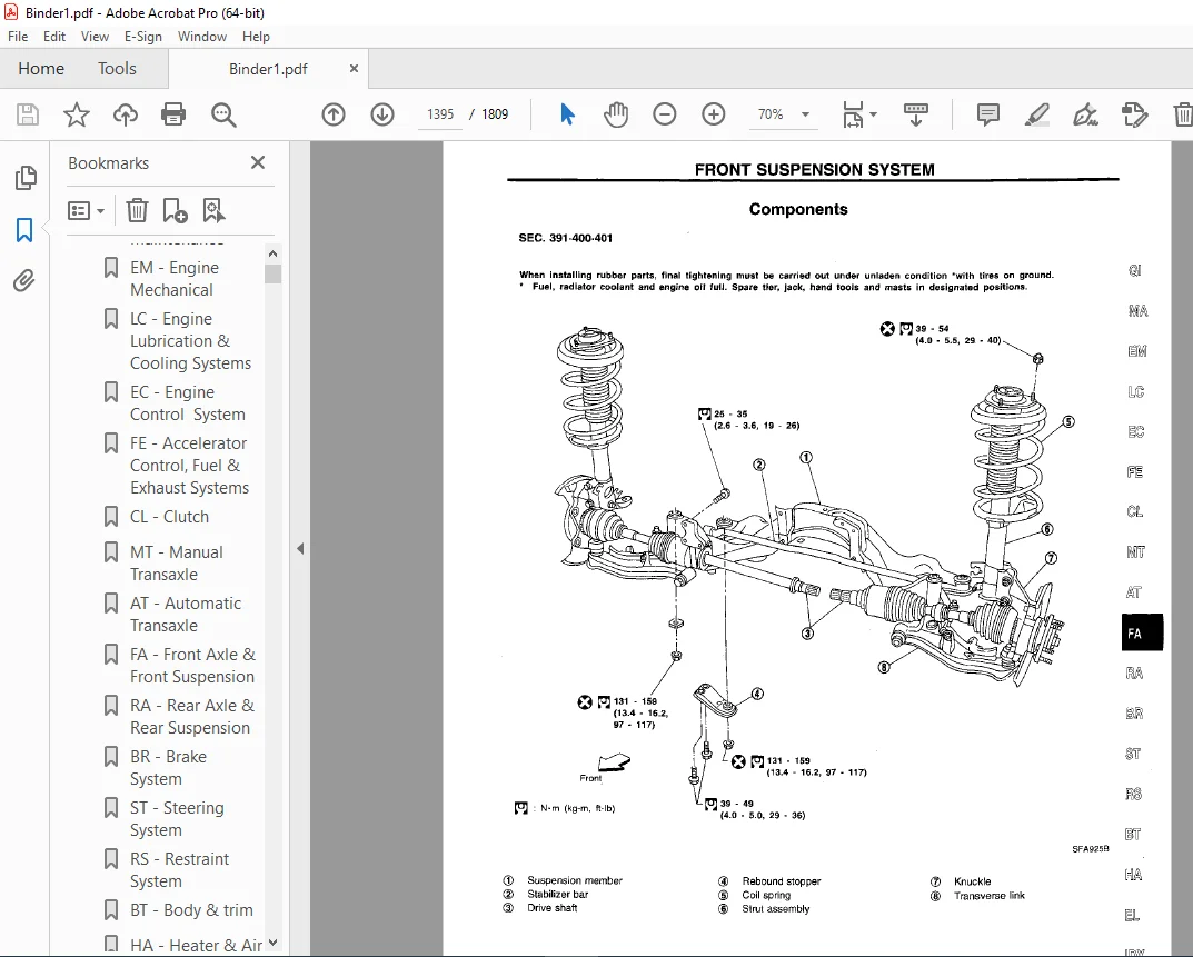
FRONT SUSPENSION SYSTEM1395
Components1395
ON-VEHICLE SERVICE1396
Front Axle and Front Suspension Parts1396
Front Wheel Bearing1397
Front Wheel Alignment1397
Drive Shaft1398
FRONT AXLE1399
Wheel Hub and Knuckle1399
Drive Shaft1403
FRONT SUSPENSION1411
Components1411
Coil Spring and Strut Assembly1412
Stabilizer Bar1413
Transverse Link and Lower Ball Joint1414
SERVICE DATA AND SPECIFICATIONS (SDS)1416
General Specifications1416
Inspection and Adjustment1416
FE1418
QUICK REFERENCE INDEX 0
TABLE OF CONTENTS1418
PREPARATION/ACCELERATOR CONTROL SYSTEM1419
Special Service Tool1419
Adjusting Accelerator Wire1419
FUEL SYSTEM1420
EXHAUST SYSTEM1421
Foldout1423
QUICK REFERENCE INDEX 0
SUPER MULTIPLE JUNCTION (SMJ)1423
TERMINAL ARRANGEMENT1423
FUSE BLOCK – JUNCTION BOX (J/B)1425
FUSE AND FUSIBLE LINK BOX1426
ELECTRICAL UNITS1427
JOINT CONNECTOR (J/C)1428
GI1429
QUICK REFERENCE GUIDE 0
TABLE OF CONTENTS1429
PRECAUTIONS1430
Precautions for Supplemental Restraint System (SRS) “AIR BAG” and “SEAT BELT PRE-TENTIONER”1430
Precautions for NVIS (Nissan Vehicle Immobiliser System –– NATS)1430
General Precautions1431
Precautions for Multiport Fuel Injection System or Engine Control System1433
Precautions for Three Way Catalyst1433
Precautions for Engine Oils1434
Precautions for Fuel1435
Precautions for Air Conditioning1435
HOW TO USE THIS MANUAL1436
HOW TO READ WIRING DIAGRAMS1438
Sample/Wiring Diagram –– EXAMPL ––1438
Description1440
HOW TO CHECK TERMINAL1447
Connector and Terminal Pin Kit1447
How to Probe Connectors1447
How to Check Enlarged Contact Spring of Terminal1448
Waterproof Connector Inspection1449
Terminal Lock Inspection1449
HOW TO PERFORM EFFICIENT DIAGNOSES FOR AN ELECTRICAL INCIDENT1450
Work Flow1450
Incident Simulation Tests1451
Circuit Inspection1454
HOW TO FOLLOW FLOW CHART IN TROUBLE DIAGNOSES1460
How to Follow This Flow Chart1461
CONSULT CHECKING SYSTEM1463
Function and System Application1463
Lithium Battery Replacement1463
Checking Equipment1464
Loading Procedure1464
CONSULT Data Link Connector (DLC) Circuit1465
IDENTIFICATION INFORMATION1466
Model Variation1466
Identification Number1467
Dimensions1469
Wheels and Tires1469
LIFTING POINTS AND TOW TRUCK TOWING1470
Preparation1470
Board-on Lift1470
Garage Jack and Safety Stand1471
2-pole Lift1472
Tow Truck Towing1473
TIGHTENING TORQUE OF STANDARD BOLTS1474
SAE J1930 TERMINOLGY LIST1475
SAE J1930 Terminology List1475
HA1479
QUICK REFERENCE INDEX 0
TABLE OF CONTENTS1479
MANUAL AND AUTO1481
PRECAUTIONS AND PREPARATION1481
Supplemental Restraint System (SRS) “AIR BAG” and “SEAT BELT PRE-TENSIONER”1481
Precautions for Working With HFC-134a (R-134a)1482
General Refrigerant Precautions1482
Precautions for Refrigerant Connection1483
Precautions for Servicing Compressor1486
Special Service Tools1486
HFC-134a (R-134a) Service Tools and Equipment1487
Precautions for Service Equipment1489
DESCRIPTION1491
Refrigeration Cycle1491
V-6 Variable Displacment Compressor1492
Component Layout1496
Discharge Air Flow1497
MANUAL1498
DESCRIPTION1498
Control Operation1498
TROUBLE DIAGNOSES1500
How to Perform Trouble Diagnoses for Quick and Accurate Repair1500
Operational Check1501
Symptom Chart1503
Preliminary Check1505
MANUAL AND AUTO1510
TROUBLE DIAGNOSES1510
Performance Test Diagnoses1510
Performance Chart1512
Trouble Dianoses for Abnormal Pressure1513
MANUAL1516
TROUBLE DIAGNOSES1516
Component Locaion1516
Circuit Diagram1518
Wiring Diagram – A/C, M –1519
Main Power Supply and Ground Circuit Check1523
Diagnostic Procedure 11524
Diagnostic Procedure 21525
Diagnostic Procedure 31528
Diagnostic Procedure 41529
Diagnostic Procedure 51531
Electrical Components Inspection1534
Control Linkage Adjustment1535
AUTO1537
DESCRIPTION1537
Introduction1537
Features1537
Control Operation1540
TROUBLE DIAGNOSES1543
How to Perform Trouble Diagnoses for Quick and Accurate Repair1543
Operational Check1544
Symptom Chart1547
Self-diagnosis1549
Preliminary Check1558
Component Location1566
Circuit Diagram1568
Wiring Diagram – A/C, A–1569
Main Power Supply and Ground Circuit Check1572
Diagnostic Procedure 11573
Diagnostic Procedure 21574
Diagnostic Procedure 31575
Diagnostic Procedure 41576
Diagnostic Procedure 51577
Diagnostic Procedure 61578
Diagnostic Procedure 71580
Diagnostic Procedure 81582
Electrical Components Inspection1585
Control Linkage Adjustment1586
SYSTEM DESCRIPTION1587
Overview of Control System1587
Control System Input Components1588
Control System Automatic Amplifier (Auto amp)1591
Control System Output Components1591
MANUAL AND AUTO1599
SERVICE PROCEDURES1599
HFC– 134a (R–134a) Service Procedure1599
Maintenance of Lubricant Quality in Compressor1601
Refrigerant Lines1603
Checking refrigerant Leaks1604
Compressor Mounting1607
Belt tension1607
Fast Idle Control Device (FICD)1607
Compressor1608
Compressor Clutch1608
SERVICE DATA AND SPECIFICATIONS (SDS)1612
General Specifications1612
Inspection and Adjustment1612
IDX1613
QUICK REFERENCE INDEX 0
LC1621
QUICK REFERENCE INDEX 0
TABLE OF CONTENTS1621
PRECAUTIONS AND PREPARATION1622
Liquid Gasket Application Procedure1622
Special Service Tools1623
ENGINE LUBRICATION SYSTEM1624
Lubrication Circuit 1624
Oil Pressure Check 1625
Oil Pump1625
ENGINE COOLING SYSTEM1628
Cooling Circuit 1628
System Check1629
Water Pump 1630
Thermostat 1634
Radiator 1635
Cooling Fan Control System1635
Radiator (Aluminum type)1636
Overheating Cause Analysis1639
SERVICE DATA AND SPECIFICATIONS (SDS)1640
Engine Lubrication System1640
Engine Cooling System1640
MA1641
QUICK REFERENCE INDEX 0
TABLE OF CONTENTS1641
PRECAUTIONS AND PREPARATION1642
Supplemental Restraint System (SRS) “AIR BAG” and “SEAT BELT PRE-TENSIONER”1642
Special Service Tool1642
Commercial Service Tool1642
GENERAL MAINTENANCE1643
PERIODIC MAINTENANCE1645
Schedule 11646
Schedule 21647
RECOMMENDED FLUIDS AND LUBRICANTS1648
Fluids and Lubricants1648
SAE Viscosity Number1648
Anti-freeze Coolant Mixture Ratio1649
ENGINE MAINTENANCE1650
Checking Drive Belts1650
Changing Engine Coolant1651
Checking Fuel Lines1652
Checking Fuel Filter1653
Changing Air Cleaner Filter1653
Changing Engine Oil1654
Changing Oil Filter1654
Changing Spark Plugs1655
Checking EVAP Vapor Lines1656
CHASSIS AND BODY MAINTENANCE1657
Checking Exhaust System1657
Checking Clutch Fluid Level and Leaks1657
Checking M/T Oil1657
Changing M/T Oil1657
Checking A/T Fluid1658
Changing A/T Fluid1658
Balancing Wheels1659
Tire Rotation1659
Checking Brake Fluid Level and Leaks1659
Checking Brake Lines and Cables1659
Checking Disc Brake1659
Checking Steering Gear and Linkage1660
Checking Power Steering Fluid and Lines1660
Lubricating Locks, Hinges and Hood Latches1661
Checking Seat Belts, Buckles, Retractors, Anchors and Adjusters1661
SERVICE DATA AND SPECIFICATIONS (SDS)1662
Engine Maintenance1662
Chasis and Body Maintenance1662
MT1663
QUICK REFERENCE INDEX 0
TABLE OF CONTENTS1663
PREPARATION1664
Special Service Tools1664
Commercial Service Tools1666
NOISE, VIBRATION AND HARSHNESS (NVH) TROUBLESHOOTING1667
NVH Troubleshooting Chart1667
DESCRIPTION1668
Cross-sectional View1668
ON-VEHICLE SERVICE/REMOVAL AND INSTALLATION1669
Replacing Oil Seal1669
Position Switch Check1670
Viscous Coupling Check1670
Removal1670
Installation1671
TRANSAXLE GEAR CONTROL1672
MAJOR OVERHAUL1673
Case Components1673
Gear Components1674
Shift Control Components1675
DISASSEMBLY1676
REPAIR FOR COMPONENT PARTS1679
Input Shaft and Gears1679
Mainshaft and Gears1684
Final Drive1688
Shift Control Components1694
Case Components1694
ADJUSTMENT1695
Input Shaft End Play and Differential Side Bearing Preload1695
Mainshaft Bearing Preload1696
ASSEMBLY1699
SERVICE DATA AND SPECIFICATIONS (SDS)1703
General Specifications1703
Inspection and Adjustment1703
RA1708
QUICK REFERENCE INDEX 0
TABLE OF CONTENTS1708
PRECAUTIONS AND PREPARATION1709
Precautions1709
Special Service Tool1709
Commercial Service tools1709
NOISE, VIBRATION AND HARSHNESS (NVH) TROUBLESHOOTING1710
NVH Troubleshooting Chart1710
REAR SUSPENSION SYSTEM1711
Components1711
ON-VEHICLE SERVICE1712
Rear Axle and Rear Suspension Parts1712
Rear Wheel Bearing1712
Rear Wheel Alignment1713
REAR AXLE1714
Wheel Hub1714
REAR SUSPENSION1717
Components1717
Removal and Installation1718
Coil Spring and Shock Absorber1718
Torsion Beam, Lateral Link and Control Rod1720
SERVICE DATA AND SPECIFICATIONS (SDS)1721
General Specifications1721
Inspection and Adjustment1721
RS1722
QUICK REFERENCE INDEX 0
TABLE OF CONTENTS1722
PRECAUTION1723
Supplemental Restraint System (SRS) “AIR BAG” and “SEAT BELT PRE-TENSIONER”1723
SEAT BELTS1724
Front Seat Belt1725
Rear Seat Belt1726
Seat Belt Inspection1727
SUPPLEMENTAL RESTRAINT SYSTEM (SRS)1730
Precautions for SRS “AIR BAG” and “SEAT BELT PRE-TENSIONER” Service1730
Special Service Tools1730
Description1731
SRS Component Parts Location1732
Maintenance Items1732
Removal And Installation – Diagnosis Sensor Unit, Seat Belt Pre-tensioner and Satellite Sensor1734
Removal – Air Bag Module and Spiral Cable1736
Removal – Front Passenger Air Bag Module1737
Removal – Side Air Bag Module1738
Installation – Air Bag Module and Spiral Cable1739
Installation – Front Passenger Air Bag Module1740
Installation – Side Air Bag Module1741
Disposal of Air Bag Module and Seat Belt Pre–tensioner1741
TROUBLE DIAGNOSES – Supplemental Restraint System (SRS)1747
Trouble Diagnoses Introduction1747
How to Perform Trouble Diagnoses for Quick and Accurate Repair1749
Schematic1751
Wiring Diagram – SRS –1752
Self-diagnosis1756
Trouble Diagnoses for Air Bag Warning Lamp1775
Trouble Diagnosis for Seat Belt Pre–tensioner Warning Lamp1777
COLLISION DIAGNOSIS1779
ST1782
QUICK REFERENCE INDEX 0
TABLE OF CONTENTS1782
PRECAUTIONS AND PREPARATIONS1783
Supplemental Restraint System (SRS) “AIR BAG” and “SEAT BELT PRE–TENSIONER”1783
Precautions for Steering System1783
Special Service Tools1784
Commercial Service Tools1785
NOISE, VIBRATION AND HARSHNESS (NVH) TROUBLESHOOTING1786
NVH Troubleshooting Chart1786
ON-VEHICLE SERVICE1787
Checking Steering Wheel Play1787
Checking Neutral Position on Steering Wheel1787
Front Wheel Turning Angle1787
Checking Gear Housing Movement1787
Checking and Adjusting Drive Belts1788
Checking Fluid Level1788
Checking Fluid Leakage1788
Bleeding Hydraulic System1788
Checking Steering Wheel Turning Force1789
Checking Hydraulic System1790
STEERING WHEEL AND STEERING COLUMN1791
Removal and Installation1791
Disassembly and Assembly1793
Inspection1794
POWER STEERING GEAR AND LINKAGE1795
Removal and Installation1795
Components1797
Disassembly1798
Inspection1798
Assembly1799
Adjustment1804
POWER STEERING OIL PUMP1805
Pre-disassembly Inspection1805
Disassembly1806
Inspection1806
Assembly1807
SERVICE DATA AND SPECIFICATIONS (SDS)1808
General Specifications1808
Inspection and Adjustment1808
DESCRIPTION:
1999 NISSAN MAXIMA A32 Series Service Manual PDF DOWNLOAD
FOREWORD
- This manual contains maintenance and repair procedures for the 1999 Nissan MAXIMA.
- In order to assure your safety and the efficient functioning of the vehicle, this manual should be read thoroughly.
- It is especially important that the PRECAUTIONS in the GI section be completely understood before starting any repair task.
- All information in this manual is based on the latest product information at the time of publication. The right is reserved to make changes in specifications and methods at any time without notice.
IMPORTANT SAFETY NOTICE
- The proper performance of service is essential for both the safety of the technician and the efficient functioning of the vehicle.
- The service methods in this Service Manual are described in such a manner that the service may be performed safely and accurately.
- Service varies with the procedures used, the skills of the technician and the tools and parts available.
- Accordingly, anyone using service procedures, tools or parts which are not specifically recommended by NISSAN must first be completely satisfied that neither personal safety nor the vehicle’s safety will be jeopardized by the service method selected.
PLEASE NOTE:
- This is the same manual used by the dealers to diagnose and troubleshoot your vehicle
- You will be directed to the download page as soon as the purchase is completed. The whole payment and downloading process will take anywhere between 2-5 minutes
- Need any other service / repair / parts manual, please feel free to contact [email protected] . We still have 50,000 manuals unlisted
G.P