Trusted Business
Verified & Licensed
Virus Free Files
100% Safe Downloads
Secure Payment
SSL Protected
Instant Delivery
Available Immediately
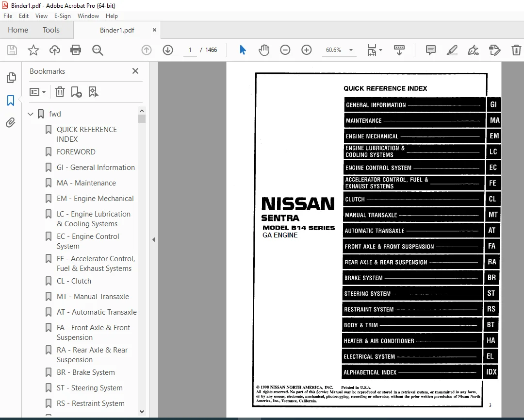
1999 NISSAN SENTRA B14 Series (GA Engine) Service Manual PDF DOWNLOAD
$24.95
1999 NISSAN SENTRA B14 Series (GA Engine) Service Manual PDF DOWNLOAD
Instant PDF Download
Available immediately
Save to Your Device
Download & keep forever
Antivirus Scanned
100% virus-free
Trusted Worldwide
175,000+ customers
Description
1999 NISSAN SENTRA B14 Series (GA Engine) Service Manual PDF DOWNLOAD
FILE DETAILS:
1999 NISSAN SENTRA B14 Series (GA Engine) Service Manual PDF DOWNLOAD
Language : English
Pages : 1466
Downloadable : Yes
File Type : PDF
IMAGES PREVIEW OF THE MANUAL:
VIDEO PRVIEW:
https://vimeo.com/853254801?share=copy
TABLE OF CONTENTS:
1999 NISSAN SENTRA B14 Series (GA Engine) Service Manual PDF DOWNLOAD
fwd.................................................................................................   1
	QUICK REFERENCE INDEX...........................................................................   1
	FOREWORD........................................................................................   2
	GI - General Information........................................................................   0
	MA - Maintenance................................................................................   0
	EM - Engine Mechanical..........................................................................   0
	LC - Engine Lubrication & Cooling Systems.......................................................   0
	EC - Engine Control System......................................................................   0
	FE - Accelerator Control, Fuel & Exhaust Systems................................................   0
	CL - Clutch.....................................................................................   0
	MT - Manual Transaxle...........................................................................   0
	AT - Automatic Transaxle........................................................................   0
	FA - Front Axle & Front Suspension..............................................................   0
	RA - Rear Axle & Rear Suspension................................................................   0
	BR - Brake System...............................................................................   0
	ST - Steering System............................................................................   0
	RS - Restraint System...........................................................................   0
	BT - Body & Trim................................................................................   0
	HA - Heater & Air Conditioner...................................................................   0
	EL - Electrical System..........................................................................   0
	IDX - Alphabetical Index........................................................................   1
	Foldout.........................................................................................   0
	GST Mode 6 - Test Value & Test Limit ...........................................................   3
at..................................................................................................   4
	QUICK REFERENCE INDEX...........................................................................   0
	TABLE OF CONTENTS...............................................................................   4
	PRECAUTIONS AND PREPARATION.....................................................................   6
		Supplemental Restraint System (SRS) "AIR BAG"...............................................   6
		Service Notice or Precautions...............................................................   6
		Special Service Tools.......................................................................   7
		Commercial Service Tools....................................................................  10
	OVERALL SYSTEM..................................................................................  11
		Circuit Diagram.............................................................................  11
		Wiring Diagram -A/T, RL -...................................................................  12
		Cross-sectional View........................................................................  14
		Hydraulic Control Circuit...................................................................  15
		Shift Mechanism.............................................................................  16
			Construction............................................................................  16
			Power Transmission......................................................................  18
		Control System..............................................................................  25
		Function of Control Valves..................................................................  26
		Hydraulic Control System....................................................................  28
			Line Pressure Control...................................................................  28
			Shift Control...........................................................................  29
				"D" position........................................................................  29
				"2" position........................................................................  30
				"1" position........................................................................  30
			Shift Timing Control....................................................................  31
			Lock-up Control.........................................................................  32
				Lock-up "OFF".......................................................................  33
				Lock-up "ON" (D4)...................................................................  33
				Torque converter clutch solenoid valve operation....................................  33
			Overdrive Control.......................................................................  33
	TROUBLE DIAGNOSIS - Basic inspection............................................................  35
		Stall Test..................................................................................  35
		Judgement of Stall Test.....................................................................  37
		Line Pressure Test..........................................................................  38
			Line Pressure Test Ports................................................................  38
			Line Pressure Test Procedure............................................................  38
			Governor Pressure Testing...............................................................  39
		Road Test...................................................................................  40
		Shift Schedule..............................................................................  40
	TROUBLE DIAGNOSIS - General Description.........................................................  44
		Symptom Chart...............................................................................  44
	TROUBLE DIAGNOSIS...............................................................................  48
		Component Inspection........................................................................  48
	TROUBLE DIAGNOSES - A/T Shift Lock System.......................................................  52
		Shift Lock System Electrical Parts Location.................................................  52
		Wiring Diagram - SFT, RL -..................................................................  53
		Diagnostic Procedure........................................................................  54
		Key Interlock Cable.........................................................................  56
		Component Check.............................................................................  57
	ON-VEHICLE SERVICE..............................................................................  59
		Control Valve Assembly and Accumulator......................................................  59
			Removal.................................................................................  59
			Installation............................................................................  60
		Control Cable Adjustment....................................................................  60
		Park/Neutral Position (PNP) Switch Adjustment...............................................  60
		Differential Side Oil Seal Replacement......................................................  61
		Throttle Wire Adjustment....................................................................  62
		Governor Valve..............................................................................  62
	REMOVAL AND INSTALLATION........................................................................  63
	MAJOR OVERHAUL..................................................................................  66
		Oil Channel.................................................................................  69
		Locations of Adjusting Shims, Needle Bearings, Trrust Washers adn Snap Rings................  70
	DISASSEMBLY.....................................................................................  71
	REPAIR FOR COMPONENT PARTS......................................................................  84
		Manual Shaft and Throttle Lever.............................................................  84
		Oil Pump....................................................................................  87
		Control Valve Assembly......................................................................  92
		Control Valve Upper Body.................................................................... 100
		Control Valve Lower Body.................................................................... 104
			Throttle Valve.......................................................................... 105
		Reverse Clutch.............................................................................. 107
		High Clutch................................................................................. 111
		Forward Clutch and Overrun Clutch........................................................... 116
		Low & Reverse Brake......................................................................... 122
		Rear Internal Gear, Forward Clutch Hub and Overrun Clutch Hub............................... 126
		Output Shaft, Output Gear, Idler Gear, Reduction Pinion Gear and Bearing Retainer........... 126
		Band Servo Piston Assembly.................................................................. 135
		Final Drive................................................................................. 140
	ASSEMBLY........................................................................................ 144
		Assembly 1.................................................................................. 144
			Reduction Pinion Gear Bearing Preload................................................... 145
			Output Shaft Bearing Preload............................................................ 147
		Assembly 2.................................................................................. 149
		Adjustment 2................................................................................ 154
			Total End Play.......................................................................... 154
			Reverse Clutch End Play................................................................. 156
		Assembly 3.................................................................................. 157
		Adjustment 3................................................................................ 159
			Final Drive End Play.................................................................... 159
		Assembly 4.................................................................................. 161
	SERVICE DATA AND SPECIFICATIONS (SDS)........................................................... 167
		General Specifications...................................................................... 167
		Specifications and Adjustments.............................................................. 168
			Input Shaft............................................................................. 171
			Planetary Carrier....................................................................... 171
			Final Drive............................................................................. 171
			Reduction Pinion Gear................................................................... 173
			Output Shaft............................................................................ 173
			Bearing Retainer........................................................................ 175
			Total End Play.......................................................................... 175
			Reverse Clutch End Play................................................................. 175
			Accumulator............................................................................. 175
			Band Servo.............................................................................. 175
			Removal and Installation................................................................ 175
br.................................................................................................. 176
	QUICK REFERENCE INDEX...........................................................................   0
	TABLE OF CONTENTS............................................................................... 176
	PRECAUTIONS AND PREPARATION..................................................................... 177
		Supplemental Restraint System (SRS) "AIR BAG"............................................... 177
		Precautions for Brake System................................................................ 177
		Commercial Service Tools.................................................................... 177
	NOISE, VIBRATION AND HARSHNESS (NVH) TROUBLESHOOTING............................................ 178
		NVH Troubleshooting Chart................................................................... 178
	ON-VEHICLE SERVICE.............................................................................. 179
		Checking Brake Fluid Level.................................................................. 179
		Checking Brake Line......................................................................... 179
		Checking Brake Fluid........................................................................ 179
		Bleeding Brake System....................................................................... 180
		Brake Burnishing Procedure.................................................................. 180
	BRAKE HYDRAULIC LINE............................................................................ 181
	CONTROL VALVE................................................................................... 183
		Proportioning Valve......................................................................... 183
	BRAKE PEDAL AND BRACKET ........................................................................ 185
	MASTER CYLINDER................................................................................. 187
	BRAKE BOOSTER................................................................................... 191
	VACUUM HOSE..................................................................................... 193
	FRONT DISC BRAKE................................................................................ 194
		Components.................................................................................. 195
	REAR DRUM BRAKE................................................................................. 198
		Components.................................................................................. 198
	REAR DISC BRAKE................................................................................. 201
		Components.................................................................................. 203
	ANTI-LOCK BRAKE SYSTEM.......................................................................... 212
		Purpose..................................................................................... 212
		Operation................................................................................... 212
		ABS Hydraulic Circuit....................................................................... 212
		System Components........................................................................... 213
		System Description.......................................................................... 213
			Actuator................................................................................ 214
				ABS actuator operation.............................................................. 214
		Removal and Installation.................................................................... 215
	TROUBLE DIAGNOSES............................................................................... 219
		How to Perform Trouble Diagnoses for Quick anad Accurate Repari............................. 219
		Preliminary Check........................................................................... 220
		Component Parts and Harness Connector Location.............................................. 221
		Schematic................................................................................... 222
		Wiring Diagram -ABS-........................................................................ 223
		Self-diagnosis.............................................................................. 227
			How To Read Self-Diagnostic Results (Malfunction codes)................................. 228
			How To Erase Self-Diagnostic Results (Malfunction codes)................................ 228
		CONSULT..................................................................................... 230
		CONSULT Inspection Procedure................................................................ 231
			Self-Diagnostic Results Mode............................................................ 232
			Data Monitor Mode....................................................................... 235
			Active Test Mode........................................................................ 235
		Ground Circuit Check........................................................................ 236
	TROUBLE DIAGNOSES FOR SYMPTOM .................................................................. 237
	SERVICE DATA AND SPECIFICATIONS (SDS)........................................................... 256
		General Specifications...................................................................... 256
		Inspection and Adjustment................................................................... 257
bt.................................................................................................. 258
	QUICK REFERENCE INDEX...........................................................................   0
	TABLE OF CONTENTS............................................................................... 258
	PRECAUTIONS AND PREPARATION..................................................................... 259
		Precautions ................................................................................ 259
		Supplemental Restraint System (SRS) "AIR BAG"............................................... 259
		Clip and Fastener........................................................................... 259
	BODY END........................................................................................ 262
		Body Front End.............................................................................. 262
		Body Rear End and Operner................................................................... 265
	DOOR............................................................................................ 268
		Front Door ................................................................................. 268
		Rear Door................................................................................... 269
	INSTRUMENT PANEL................................................................................ 270
	INTERIOR TRIM................................................................................... 273
		Side and Floor Trim......................................................................... 273
		Door Trim................................................................................... 275
		Roof Trim................................................................................... 277
		Trunk Room Trim............................................................................. 278
	EXTERIOR........................................................................................ 279
		Hood front seal............................................................................. 279
		Cowl top seal and cowl top grille........................................................... 279
		Windshield side molding..................................................................... 279
		Windshield upper molding.................................................................... 280
		Drip Weatherstrip........................................................................... 280
		Body side welt.............................................................................. 280
		Door  weatherstrip.......................................................................... 280
		Rear window upper molding and side molding.................................................. 280
		Rear window molding and side molding........................................................ 280
		Rear window lower molding................................................................... 280
		Door sash molding........................................................................... 281
		Rear door parting seal...................................................................... 281
		Rear door comer molding..................................................................... 281
		Door outside molding........................................................................ 281
		Sunroof lid weatherstrip.................................................................... 282
		Side guard molding.......................................................................... 282
		Trunk lid weatherstrip...................................................................... 282
		Trunk lid finisher.......................................................................... 282
		Rear combination lamp....................................................................... 283
		Fender and center mudguard.................................................................. 284
		Rear air spoiler and high-mounted stop lamp................................................. 284
	SEAT............................................................................................ 285
		Front Seat ................................................................................. 285
		Rear Seat................................................................................... 286
	SUNROOF......................................................................................... 287
		Removal .................................................................................... 288
		Trouble Diagnoses........................................................................... 289
			Drain Hoses............................................................................. 290
			Weatherstrip............................................................................ 290
			Link And Wire Assembly.................................................................. 290
		Adjustment.................................................................................. 291
	WINDSHIELD AND WINDOWS.......................................................................... 292
		Windshield and Rear Window.................................................................. 293
		Quarter Window.............................................................................. 294
	MIRROR.......................................................................................... 295
		Door Mirror................................................................................. 295
	BODY ALIGNMENT.................................................................................. 296
		Engine Compartment.......................................................................... 296
		Underbody................................................................................... 298
cl.................................................................................................. 300
	QUICK REFERENCE INDEX...........................................................................   0
	TABLE OF CONTENTS............................................................................... 300
	PRECAUTIONS AND PREPARATION..................................................................... 301
		Precaution.................................................................................. 301
		Special Service Tools....................................................................... 301
	NOISE, VIBRATION AND HARSHNESS (NVH) TROUBLESHOOTING............................................ 302
		NVH Troubleshooting Chart................................................................... 302
	CLUTCH SYSTEM................................................................................... 303
	INSPECTION AND ADJUSTMENT....................................................................... 304
		Adjusting Clutch Pedal...................................................................... 304
	CLUTCH RELEASE MECHANISM........................................................................ 305
	CLUTCH DISC AND CLUTCH COVER.................................................................... 306
		Clutch Disc................................................................................. 306
		Clutch Cover and Flywheel................................................................... 307
	SERVICE DATA AND SPECIFICATIONS (SDS)........................................................... 308
		General Specifications...................................................................... 308
		Inspection and Adjustment................................................................... 308
ec.................................................................................................. 309
	QUICK REFERENCE INDEX...........................................................................   0
	TABLE OF CONTENTS............................................................................... 309
	DIAGNOSTIC TROUBLE CODE INDEX................................................................... 312
		Alphabetical & P No. Index for DTC.......................................................... 312
	PRECAUTIONS AND PREPARATION..................................................................... 314
		Special Service Tools....................................................................... 314
		Commercial Service Tools.................................................................... 314
		Supplemental Restraint System (SRS) "AIR BAG"............................................... 315
		Precautions for On Board Diagnostic (OBD) System of Engine.................................. 315
		Engine Fuel & Emission Control System....................................................... 316
		Precautions................................................................................. 317
	ENGINE AND EMISSION CONTROL OVERALL SYSTEM...................................................... 319
		Circuit Diagram............................................................................. 319
		System Diagram.............................................................................. 320
		Engine Control Component Parts Location..................................................... 321
		Vacuum Hose Drawing......................................................................... 324
		System Chart................................................................................ 325
	ENGINE AND EMISSION BASIC CONTROL SYSTEM DESCRIPTION............................................ 326
		Multiport Fuel Injection (MFI) System....................................................... 326
		Distributor Ignition (DI) System............................................................ 328
		Air Conditioning Cut Control................................................................ 329
		Fuel Cut Control............................................................................ 330
	EVAPORATIVE EMISSION SYSTEM..................................................................... 331
		Description................................................................................. 331
		Inspection.................................................................................. 331
		Evaporative Emission Line Drawing........................................................... 334
		On Board Refueling Vapor Recovery (ORVR).................................................... 336
	POSITIVE CRANKCASE VENTILATION.................................................................. 341
		Description................................................................................. 341
		Inspection.................................................................................. 341
	BASIC SERVICE PROCEDURE......................................................................... 342
		Fuel Pressure Release....................................................................... 342
		Fuel Pressure Check......................................................................... 342
		Fuel Pressure Regulator Check............................................................... 343
		Injector Removal and Installation........................................................... 343
		Fast Idle Cam (FIC)......................................................................... 343
		Idle Speed/Ignition Timing/Idle Mixture Ratio............................................... 346
		Adjustment.................................................................................. 346
	ON BOARD DIAGNOSTIC SYSTEM DESCRIPTION.......................................................... 352
		Introduction................................................................................ 352
		Two Trip Detection Logic.................................................................... 352
		Emission-related Diagnostic Information..................................................... 353
		Malfunction Indicator Lamp (MIL)............................................................ 363
		OBD System Operation Chart.................................................................. 367
		CONSULT..................................................................................... 372
		Generic Scan Tool (GST)..................................................................... 386
	TROUBLE DIAGNOSIS - Introduction................................................................ 388
		Introduction................................................................................ 388
		Diagnostic Worksheet........................................................................ 388
		Work Flow................................................................................... 390
		Description for Work Flow................................................................... 391
	TROUBLE DIAGNOSIS - Basic Inspection............................................................ 392
		Basic Inspection............................................................................ 392
	TROUBLE DIAGNOSIS - General Description......................................................... 397
		Diagnostic Trouble Code (DTC) Inspection Priority Chart..................................... 397
		Fail-Safe Chart............................................................................. 398
		Symptom Matrix Chart........................................................................ 399
		CONSULT Reference Value in Data Monitor Mode................................................ 402
		Major Sensor Reference Graph in Data Monitor Mode........................................... 405
		ECM Terminals and Reference Value........................................................... 407
	TROUBLE DIAGNOSIS FOR INTERMITTENT INCIDENT..................................................... 416
		Description................................................................................. 416
		Common I/I Report Situations................................................................ 416
		Diagnostic Procedure........................................................................ 416
	TROUBLE DIAGNOSIS FOR POWER SUPPLY.............................................................. 417
		Main Power Supply and Ground Circuit........................................................ 417
	DTC P0100, Mass Air Flow Sensor (MAFS).......................................................... 422
	DTC P0105, Absolute Pressure Sensor............................................................. 431
	DTC P0110, Intake Air Temperature Sensor........................................................ 440
	DTC P0115, Engine Coolant Temperature Sensor (ECTS) (Circuit)................................... 446
	DTC P0120, Throttle Position Sensor............................................................. 451
	DTC P0125, Engine Coolant Temperature (ECT) Sensor.............................................. 465
	DTC P0130, Front Heated Oxygen Sensor (Circuit) (Front HO2S).................................... 471
	DTC P0131, Front Heated Oxygen Sensor (Lean Shift Monitoring) (Front HO2S)...................... 478
	DTC P0132, Front Heated Oxygen Sensor (Rich Shift Monitoring) (Front HO2S)...................... 485
	DTC P0133, Front Heated Oxygen Sensor (Response Monitoring) (Front HO2S)........................ 492
	DTC P0134, Front Heated Oxygen Sensor (High Voltage) (Front HO2S)............................... 500
	DTC P0135, Front Heated Oxygen Sensor Heater.................................................... 507
	DTC P0137, Rear Heated Oxygen Sensor (Min. Voltage Monitoring) (Rear HO2S)...................... 511
	DTC P0138, Rear Heated Oxygen Sensor (Max. Voltage Monitoring) (Rear HO2S)...................... 518
	DTC P0139, Rear Heated Oxygen Sensor (Response Monitoring) (Rear HO2S).......................... 525
	DTC P0140, Rear Heated Oxygen Sensor (High Voltage) (Rear HO2S)................................. 532
	DTC P0141, Rear Heated Oxygen Sensor Heater..................................................... 537
	DTC P0171, Fuel Injection System Function (Lean side)........................................... 541
	DTC P0172, Fuel Injection System Function (Rich side)........................................... 547
	DTC P0180, Tank Fuel Temperature Sensor......................................................... 552
	DTC P0300 - P0304, No. 4 - 1 Cylinder Misfire, Multiple Cylinder Misfire........................ 556
	DTC P0325, Knock Sensor (KS).................................................................... 561
	DTC P0335, Crankshaft Position Sensor (CKPS) (OBD).............................................. 566
	DTC P0340, Camshaft Position Sensor (CMPS)...................................................... 571
	DTC P0400, ECR Function (Close)................................................................. 579
	DTC P0402, ECRC-BPT Valve Function.............................................................. 588
	DTC P0420, Three Way Catalyst Function.......................................................... 593
	DTC P0440, Evaporative Emission (EVAP) Control System (Small Leak) (Negative Pressure).......... 597
	DTC P0443, Evaporative Emission (EVAP) Canister Purge Volume Control Valve (Circuit)............ 609
	DTC P0446, Evaporative Emission (EVAP) Canister Vent Control Valve (Circuit).................... 615
	DTC P0450, Evaporative Emission (EVAP) Control System Pressure Sensor........................... 620
	DTC P0500, Vehicle Speed Sensor (VSS)........................................................... 626
	DTC P0505, Idle Air Control Valve (IACV) - Auxiliary Air Control (AAC) Valve.................... 631
	DTC P0510, Closed Throttle Position Switch...................................................... 638
	DTC P0605, Engine Control Module (ECM).......................................................... 644
	DTC P1105, Manifold Absolute Pressure (MAP)/Barometric Pressure (BARO) Switch Solenoid Valve.... 646
	DTC P1110, Intake Valve Timing Control.......................................................... 655
	DTC P1148, Closed Loop Control.................................................................. 663
	DTC P1320, Ignition Signal...................................................................... 665
	DTC P1336, Crankshaft Position Sensor (CKPS) (OBD) (COG)........................................ 672
	DTC P1400, ECRC-Solenoid Valve.................................................................. 677
	DTC P1401, ECR Temperature Sensor............................................................... 682
	DTC P1402, ECR Function (Open).................................................................. 689
	DTC P1440, Evaporative Emission (EVAP) Control System (Small Leak) (Positive Pressure).......... 696
	DTC P1444, Evaporative Emission (EVAP) Canister Purge Volume Control Valve...................... 709
	DTC P1446, Evaporative Emission (EVAP) Canister Vent Control Valve (Close)...................... 717
	DTC P1447, Evaporative Emission (EVAP) Control System Purge Flow Monitoring..................... 722
	DTC P1448, Evaporative Emission (EVAP) Canister Vent Control Valve (Open)....................... 731
	DTC P1490, Vacuum Cut Valve Bypass Valve (Circuit).............................................. 737
	DTC P1491, Vacuum Cut  Valve Bypass Valve....................................................... 742
	DTC P1492, Evaporative Emission (EVAP) Canister Purge Control Valve/Solenoid Vale (Circuit)..... 748
	DTC P1493, Evaporative Emission (EVAP) Canister Purge Control Valve/Solenoid Valve.............. 754
	DTC P1706, Park/Neutral Position (PNP) Switch................................................... 763
	DTC P1775, Torque Converter Clutch Solenoid Valve (Circuit)..................................... 768
	DTC P1776, Torque Converter Clutch Solenoid Valve............................................... 773
	TROUBLE DIAGNOSIS FOR OVERHEAT.................................................................. 778
		Overheat.................................................................................... 778
	TROUBLE DIAGNOSIS FOR NON-DETECTABLE ITEMS...................................................... 791
		Injector ................................................................................... 791
		Start Signal................................................................................ 794
		Fuel Pump................................................................................... 797
		Power Steering Oil Pressure Switch.......................................................... 801
		IACV-FICD Solenoid Valve.................................................................... 805
		Electric Load Signal........................................................................ 809
		MIL & Data Link Connectors.................................................................. 813
	SERVICE DATA AND SPECIFICATION (SDS)............................................................ 814
		General Specifications...................................................................... 814
		Inspection and Adjustment................................................................... 814
el.................................................................................................. 816
	QUICK REFERENCE INDEX...........................................................................   0
	TABLE OF CONTENTS............................................................................... 816
	PRECAUTIONS AND PREPARATION..................................................................... 818
	HARNESS CONNECTOR............................................................................... 820
	STANDARDIZED RELAY.............................................................................. 822
	POWER SUPPLY ROUTING............................................................................ 824
		Schematic................................................................................... 824
		Wiring Diagram -POWER-...................................................................... 826
		Fuse........................................................................................ 832
		Fusible Link................................................................................ 832
		Circuit Breaker Inspection.................................................................. 832
	GROUND DISTRIBUTION............................................................................. 833
	BATTERY......................................................................................... 837
		How to Handle Battery....................................................................... 837
		Service Data and Specifications (SDS)....................................................... 840
	STARTING SYSTEM................................................................................. 841
		System Description.......................................................................... 841
		Wiring Diagram -START-...................................................................... 843
		Construction................................................................................ 846
		Pinion/Clutch Check......................................................................... 849
		Service Data and Specifications (SDS)....................................................... 849
	CHARGING SYSTEM................................................................................. 850
		System Description.......................................................................... 850
		Wiring Diagram -CHARGE-..................................................................... 851
		Trouble Diagnoses........................................................................... 852
		Construction................................................................................ 853
		Diode Check................................................................................. 854
		Disassembly and Assembly.................................................................... 855
		Service Data and Specifications (SDS)....................................................... 856
	COMBINATION SWITCH.............................................................................. 857
		Check....................................................................................... 857
		Replacement................................................................................. 858
	STEERING SWITCH................................................................................. 859
		Check....................................................................................... 859
	HEADLAMP........................................................................................ 860
		System Description (For USA)................................................................ 860
		Wiring Diagram (For USA) -H/LAMP-........................................................... 861
		Trouble Diagnoses (For USA)................................................................. 862
		Bulb Replacement............................................................................ 863
		Aiming Adjustment........................................................................... 863
	HEADLAMP -Daytime Light System.................................................................. 864
		System Description (For Canada)*............................................................ 864
		Operation (For Canada)...................................................................... 865
		Schematic (For Canada)...................................................................... 866
		Wiring Diagram (For Canada) -DTRL-.......................................................... 867
		Trouble Diagnoses (For Canada).............................................................. 870
		Bulb Replacement............................................................................ 871
		Aiming Adjustment........................................................................... 871
	BACK-UP LAMP.................................................................................... 872
	LICENSE, TAIL AND STOP LAMPS.................................................................... 874
	FRONT FOG LAMP.................................................................................. 876
		System Description.......................................................................... 876
		Wiring Diagram -F/FOG-...................................................................... 877
		Aiming Adjustment........................................................................... 871
	TURN SIGNAL AND HAZARD WARNING LAMPS............................................................ 879
		System Description.......................................................................... 879
		Wiring Diagram -TURN-....................................................................... 882
		Trouble Diagnoses........................................................................... 884
		Electrical Component Inspection............................................................. 884
	ILLUMINATION.................................................................................... 885
	INTERIOR AND TRUNK ROOM LAMPS................................................................... 888
		System Description ......................................................................... 888
		Wiring Diagram -INT/L-...................................................................... 890
		Trouble Diagnoses (For models with power door locks)........................................ 893
	METERS AND GAUGES/WITH TACHOMETER............................................................... 894
		System Description.......................................................................... 894
		Combination Meter........................................................................... 895
		Wiring Diagram -METER-...................................................................... 896
		Trouble Diagnoses........................................................................... 897
	METERS AND GAUGES/WITHOUT TACHOMETER............................................................ 904
		System Description.......................................................................... 904
		Combination Meter........................................................................... 905
		Wiring Diagram -METER-...................................................................... 906
		Trouble Diagnoses........................................................................... 907
	WARNING LAMPS................................................................................... 912
		System Description.......................................................................... 912
		Schematic................................................................................... 914
		Wiring Diagram -WARN-....................................................................... 915
		Schematic................................................................................... 918
		Wiring Diagram -WARN-....................................................................... 919
		Electrical Component Inspection............................................................. 922
	WARNING CHIME................................................................................... 924
		System Description.......................................................................... 924
		Wiring Diagram -CHIME-...................................................................... 926
		Trouble Diagnoses........................................................................... 928
		Electrical Components Inspection............................................................ 934
	WIPER AND WASHER................................................................................ 936
		System Description.......................................................................... 936
		Wiring Diagram -WIPER-...................................................................... 938
		Trouble Diagnoses........................................................................... 941
		Wiper Installation and Adjustment........................................................... 943
		Washer Nozzle Adjustment.................................................................... 944
	HORN............................................................................................ 945
	CIGARETTE LIGHTER............................................................................... 946
	REAR WINDOW DEFOGGER............................................................................ 947
		System Description.......................................................................... 947
		Wiring Diagram -DEF-........................................................................ 948
		Trouble Diagnoses........................................................................... 950
		Filament Check.............................................................................. 952
		Filament Repair............................................................................. 953
	AUDIO........................................................................................... 955
		System Description.......................................................................... 955
		Wiring Diagrm -AUDIO-....................................................................... 956
		Trouble Diagnoses........................................................................... 957
		Inspection.................................................................................. 958
	ELECTRIC SUNROOF................................................................................ 959
	DOOR MIRROR..................................................................................... 960
	AUTOMATIC SPEED CONTROL DEVICE (ASCD)........................................................... 961
		Component Parts and Harness Connector Location.............................................. 961
		System Description.......................................................................... 962
		Schematic................................................................................... 964
		Wiring Diagram -ASCD-....................................................................... 965
		Fail-safe System Description................................................................ 972
		Fail-safe System Check...................................................................... 973
		Trouble Diagnoses........................................................................... 974
		ASCD Wire Adjustment........................................................................ 982
		Electrical Component Iinspection............................................................ 983
	POWER WINDOW.................................................................................... 985
		System Description.......................................................................... 985
		Wiring Diagram -WINDOW-..................................................................... 988
		Trouble Diagnoses........................................................................... 990
	POWER DOOR LOCK................................................................................. 991
		System Description.......................................................................... 991
		Schematic................................................................................... 993
		Wiring Diagram -D/LOCK-..................................................................... 994
		Trouble Diagnoses........................................................................... 998
	MULTI-REMOTE CONTROL SYSTEM.....................................................................1006
		System Description..........................................................................1006
		Schematic...................................................................................1008
		Wiring Diagram -MULTI-......................................................................1009
		Trouble Diagnoses...........................................................................1013
		ID Code Entry Procedure.....................................................................1019
	THEFT WARNING SYSTEM............................................................................1020
		Component Parts and Harness Connector Location..............................................1020
		System Description..........................................................................1021
		Schematic...................................................................................1024
		Wiring Diagram -THEFT-......................................................................1025
		Trouble Diagnosis...........................................................................1031
	SMART ENTRANCE CONTROL UNIT.....................................................................1045
		Description.................................................................................1045
		Input/Output Operation Signal...............................................................1046
	LOCATION OF ELECTRICAL UNITS....................................................................1047
	HARNESS LAYOUT..................................................................................1049
		Main Harness................................................................................1052
		Engine Room Harness.........................................................................1054
		Engine Control Harness......................................................................1058
		Engine Harness No. 2 and Generator Harness..................................................1059
		Body Harness No. 2..........................................................................1061
		Room Lamp Harness...........................................................................1062
		Tail Harness................................................................................1062
		Air Bag Harness.............................................................................1063
		Front Door Harness..........................................................................1064
		Rear Door Harness...........................................................................1065
	BULB SPECIFICATIONS.............................................................................1066
	WIRING DIAGRAM CODES (CELL CODES)...............................................................1067
em..................................................................................................1068
	QUICK REFERENCE INDEX...........................................................................   0
	TABLE OF CONTENTS...............................................................................1068
	PRECAUTIONS.....................................................................................1070
		Parts Requiring Angular Tightening..........................................................1070
		Liquid Gasket Application Procedure.........................................................1070
	PREPARATION.....................................................................................1071
		Special Service Tools.......................................................................1071
		Commercial Service Tools....................................................................1074
	NOISE, VIBRATION AND HARSHNESS (NVH) TROUBLESHOOTING............................................1076
		NVH Troubleshooting Chart - ENGINE NOISE....................................................1076
	OUTER COMPONENT PARTS...........................................................................1078
	COMPRESSION PRESSURE............................................................................1082
		Measurement of Compression Pressure.........................................................1082
	OIL PAN.........................................................................................1083
		Removal.....................................................................................1083
		Installation................................................................................1084
	TIMING CHAIN....................................................................................1085
		Removal ....................................................................................1086
		Inspection..................................................................................1089
		Installation................................................................................1089
	OIL SEAL REPLACEMENT............................................................................1096
		Valve Oil Seal..............................................................................1096
		Front Oil Seal..............................................................................1096
		Rear Oil Seal...............................................................................1097
	CYLINDER HEAD...................................................................................1098
		Removal.....................................................................................1099
		Disassembly.................................................................................1099
		Inspection..................................................................................1099
			Cylinder Head Distortion................................................................1099
			Camshaft Visual Check...................................................................1099
			Camshaft Runout.........................................................................1100
			Camshaft Cam Height.....................................................................1100
			Camshaft Journal Clearance..............................................................1100
			Camshaft End Play.......................................................................1100
			Camshaft Sprocket Runout................................................................1101
			Valve Guide Clearance...................................................................1101
			Valve Guide Replacement.................................................................1102
			Valve Seats.............................................................................1103
			Replacing Valve Seat For Service Parts..................................................1103
			Valve Dimensions........................................................................1104
			Valve Spring............................................................................1104
			Valve Lifter............................................................................1104
		Assembly....................................................................................1105
		Installation................................................................................1105
	VALVE CLEARANCE.................................................................................1106
		Checking....................................................................................1106
		Adjusting...................................................................................1106
	ENGINE REMOVAL..................................................................................1109
		Removal ....................................................................................1110
		Installation................................................................................1112
	CYLINDER BLOCK..................................................................................1113
		Disassembly.................................................................................1114
			Piston And Crankshaft...................................................................1114
		Inspection..................................................................................1114
			Piston And Piston Pin Clearance.........................................................1114
			Piston Ring Side Clearance..............................................................1115
			Piston Ring End Gap.....................................................................1115
			Connecting Rod Bend and Torsion.........................................................1115
			Cylinder Block Distortion and Wear......................................................1116
			Piston-To-Bore Clearance................................................................1116
			Crankshaft..............................................................................1117
			Bearing Clearance.......................................................................1118
				Method A (Using bore gauge and micrometer)..........................................1118
				Method B (Using Plastigage).........................................................1120
			Connecting Rod Bushing Clearance (Small end)............................................1120
			Replacement of Connecting Rod Bushing (Small end).......................................1120
			Flywheel/Driveplate Runout..............................................................1120
		Assembly....................................................................................1121
			Piston..................................................................................1121
			Crankshaft..............................................................................1122
	SERVICE DATA AND SPECIFICATIONS (SDS)...........................................................1124
		General Specifications......................................................................1124
		Inspection and Adjustment...................................................................1124
		Compression Pressure........................................................................1124
		Cylinder Head...............................................................................1124
		Valve.......................................................................................1124
		Camshaft And Camshaft Bearing...............................................................1128
		Cylinder Block..............................................................................1128
		Piston, Piston Ring and Piston Pin..........................................................1129
		Connecting Rod..............................................................................1129
		Crankshaft..................................................................................1129
		Main Bearing ...............................................................................1130
		Connecting Rod Bearing......................................................................1130
		Bearing Clearance...........................................................................1130
		Miscellaneous Components....................................................................1130
fa..................................................................................................1131
	QUICK REFERENCE INDEX...........................................................................   0
	TABLE OF CONTENTS...............................................................................1132
	PRECAUTIONS AND PREPARATION.....................................................................1132
		Precautions.................................................................................1132
		Special Service Tools.......................................................................1132
			Commercial Service Tools................................................................1133
	NOISE, VIBRATION AND HARSHNESS (NVH) TROUBLESHOOTING............................................1134
		NVH Troubleshooting Chart...................................................................1134
	FRONT SUSPENSION SYSTEM.........................................................................1135
		Components..................................................................................1135
	ON-VEHICLE SERVICE..............................................................................1136
		Front Axle and Front Suspension Parts.......................................................1136
		Front Wheel Bearing.........................................................................1137
		Front Wheel Alignment.......................................................................1137
		Drive Shaft.................................................................................1138
	FRONT AXLE......................................................................................1139
		Wheel Hub and Knuckle.......................................................................1139
			Removal.................................................................................1139
			Installation............................................................................1141
			Disassembly.............................................................................1141
			Inspection..............................................................................1142
			Assembly................................................................................1142
		Drive Shaft.................................................................................1144
			Removal.................................................................................1144
			Installation............................................................................1145
			Components..............................................................................1146
			Disassembly.............................................................................1147
			Inspection..............................................................................1148
			Assembly................................................................................1149
	FRONT SUSPENSION................................................................................1151
		Components..................................................................................1151
		Coil Spring and Strut Assembly..............................................................1152
			Removal And Installation................................................................1152
			Disassembly.............................................................................1152
			Inspection..............................................................................1152
			Assembly................................................................................1153
		Stabilizer Bar..............................................................................1153
			Removal and Installation................................................................1153
			Inspection..............................................................................1154
		Transverse Link and Lower Ball Joint........................................................1154
			Removal and Installation................................................................1154
			Inspection..............................................................................1155
	SERVICE DATA AND SPECIFICATION (SDS)............................................................1156
		General Specifications......................................................................1156
		Inspection and Adjustment...................................................................1157
fe..................................................................................................1158
	QUICK REFERENCE INDEX...........................................................................   0
	TABLE OF CONTENTS...............................................................................1158
	ACCELERATOR CONTROL SYSTEM......................................................................1159
		Accelerator Control System..................................................................1159
		Adjusting Accelerator Wire..................................................................1159
	FUEL SYSTEM.....................................................................................1160
		Fuel Tank...................................................................................1160
	FUEL SYSTEM.....................................................................................1162
		Fuel Pump and Gauge.........................................................................1162
			Removal.................................................................................1162
			Installation............................................................................1162
	EXHAUST SYSTEM..................................................................................1163
foldout.............................................................................................1165
	QUICK REFERENCE INDEX...........................................................................   0
	SUPER MULTIPLE JUNCTION (SMJ) Installation......................................................1165
	SUPERMULTIPLE JUNCTION (SMJ) Terminal Arrangement...............................................1166
	FUSE BLOCK......................................................................................1167
	FUSE AND FUSIBLE LINK BOX.......................................................................1168
	JOINT CONNECTOR.................................................................................1169
	ELECTRICAL UNITS................................................................................1170
gi..................................................................................................1171
	QUICK REFERENCE INDEX...........................................................................   0
	TABLE OF CONTENTS...............................................................................1171
	PRECAUTIONS AND PREPARATION.....................................................................1172
		Supplemental Restraint System (SRS) "AIR BAG"...............................................1172
		General Precautions.........................................................................1173
		Precautions for Multiport Fuel Injection System or Engine Control System....................1175
		Precautions for Three Way Catalyst..........................................................1175
		Precautions for Engine Oils.................................................................1175
		Precautions for Fuel........................................................................1176
		Precautions for Air Conditioning............................................................1176
	HOW TO USE THIS MANUAL..........................................................................1177
	HOW TO READ WIRING DIAGRAMS.....................................................................1179
		Sample/Wiring Diagram - EXAMPL -............................................................1179
		Description.................................................................................1181
	HOW TO CHECK TERMINAL...........................................................................1187
		Connector and Terminal Pin Kit..............................................................1187
		How to Probe Connectors.....................................................................1187
		How to Check Enlarged Contact Spring of Terminal............................................1188
		Waterproof Connector Inspection.............................................................1189
		Terminal Lock Inspection....................................................................1189
	HOW TO PERFORM EFFICIENT DIAGNOSIS FOR AN ELECTRICAL INCIDENT...................................1190
		Work Flow...................................................................................1190
		Incident Simulation Tests...................................................................1191
		Circuit Inspection..........................................................................1193
	HOW TO FOLLOW FLOW CHART IN TROUBLE DIAGNOSES...................................................1200
		How to Follow This Flow Chart...............................................................1201
	CONSULT CHECKING SYSTEM.........................................................................1203
		Function and System Application.............................................................1203
		Lithium Battery Replacement.................................................................1203
		Checking Equipment..........................................................................1203
		Loading Procedure...........................................................................1204
		CONSULT Data Link Connector (DLC) Circuit...................................................1204
	IDENTIFICATION INFORMATION......................................................................1205
		Model Variation.............................................................................1205
		Identification Number.......................................................................1206
		Dimensions..................................................................................1208
		Wheels and Tires............................................................................1208
	LIFTING POINTS AND TOW TRUCK TOWING ............................................................1209
		Preparation.................................................................................1209
		Board-On Lift...............................................................................1210
		Garage Jack and Safety Stand................................................................1210
		2-pole Lift.................................................................................1211
		Tow Truck Towing............................................................................1211
	TIGHTENING TORQUE OF STANDARD BOLTS ............................................................1213
	SAE J1930 TERMINOLOGY LIST......................................................................1214
ha..................................................................................................1218
	QUICK REFERENCE INDEX...........................................................................   0
	TABLE OF CONTENTS...............................................................................1218
	PRECAUTIONS AND PREPARATION.....................................................................1219
		Supplemental Restraint System (SRS) "AIR BAG"...............................................1219
		Precautions for Working With HFC-134a (R-134a)..............................................1219
		General Refrigerant Precautions.............................................................1220
		Precautions for Refrigerant Connection......................................................1221
		Precautions for Servicing Compressor........................................................1224
		Special Service Tools.......................................................................1225
		R-134a Service Tools and Equipment..........................................................1226
		Commercial Service Tools....................................................................1226
		Precautions for Service Equipment...........................................................1228
			Calibration.............................................................................1229
	DESCRIPTION.....................................................................................1230
		Refrigeration Cycle.........................................................................1230
		Component Layout............................................................................1231
		Control Operation...........................................................................1232
		Discharge Air Flow..........................................................................1233
		Component Location..........................................................................1234
		Circuit Diagram - Air Conditioner...........................................................1236
		Wiring Diagram -Heater-.....................................................................1237
		Wiring Diagram -AC-.........................................................................1238
	TROUBLE DIAGNOSES...............................................................................1241
		How to Perform Trouble Diagnoses for Quick and Accurate Repair..............................1241
		Operational Check...........................................................................1242
		Blower Motor Circuit........................................................................1244
		Air Outlet..................................................................................1248
		Air Mix Door................................................................................1250
		Intake Door.................................................................................1252
		Magnet Clutch Circuit.......................................................................1255
		Trouble Diagnoses For Insufficient Cooling..................................................1262
		Performance Test Diagnoses..................................................................1264
		Performance Chart...........................................................................1266
		Trouble Diagnoses for Abnormal Pressure.....................................................1267
		Trouble Diagnoses for Insufficient Heating..................................................1271
		Trouble Diagnoses for Noise.................................................................1273
	SERVICE PROCEDURES..............................................................................1274
		Refrigerant Lines...........................................................................1274
		Checking Refrigerant Leaks..................................................................1275
		R-134a Service Procedure....................................................................1278
		Compressor Lubricant Quantity...............................................................1280
		Compressor Mounting.........................................................................1282
		Belt Tension................................................................................1282
		Fast Idle Control Device (FICD).............................................................1283
		Compressor..................................................................................1283
		Compressor Clutch...........................................................................1283
		Thermal Protector...........................................................................1286
		Heater Unit (Heater Core)...................................................................1286
		Cooling Unit................................................................................1287
		Control Assembly............................................................................1288
	SERVICE DATA AND SPECIFICATIONS (SDS)...........................................................1289
		General Specifications......................................................................1289
		Inspection and Adjustment...................................................................1289
idx.................................................................................................1290
	QUICK REFERENCE INDEX...........................................................................   0
lc..................................................................................................1299
	QUICK REFERENCE INDEX...........................................................................   0
	TABLE OF CONTENTS...............................................................................1299
	PRECAUTIONS.....................................................................................1300
		Liquid Gasket Application Procedure.........................................................1300
	PREPARATION.....................................................................................1301
		Special Service Tools.......................................................................1301
	ENGINE LUBRICATION SYSTEM.......................................................................1302
		Lubrication Circuit.........................................................................1302
		Oil Pressure Check..........................................................................1303
		Oil Pump....................................................................................1304
	ENGINE COOLING SYSTEM...........................................................................1306
		Cooling Circuit.............................................................................1306
		System Check................................................................................1306
		Water Hose Drawing..........................................................................1307
		Water Pump..................................................................................1309
		Thermostat..................................................................................1310
		Water Outlet................................................................................1311
		Radiator....................................................................................1312
		Radiator (Aluminum type)....................................................................1313
	ENGINE COOLING SYSTEM...........................................................................1316
		Overheating Cause Analysis..................................................................1316
	SERVICE DATA AND SPECIFICATIONS (SDS)...........................................................1317
		Engine Lubrication System...................................................................1317
		Engine Cooling System.......................................................................1317
ma..................................................................................................1318
	QUICK REFERENCE INDEX...........................................................................   0
	TABLE OF CONTENTS...............................................................................1318
	PRECAUTIONS AND PREPARATION.....................................................................1319
		Supplemental Restraint System (SRS) "AIR BAG"...............................................1319
		Special Service Tool........................................................................1319
		Commercial Service Tool.....................................................................1319
	GENERAL MAINTENANCE.............................................................................1320
	PERIODIC MAINTENANCE............................................................................1322
		Schedule 1..................................................................................1323
		Schedule 2..................................................................................1324
	RECOMMENDED FLUIDS AND LUBRICANTS...............................................................1325
		Fluids and Lubricants.......................................................................1325
		SAE Viscosity Number........................................................................1325
		Antifreeze Coolant Mixture Ratio............................................................1326
	ENGINE MAINTENANCE..............................................................................1327
		Checking Drive Belts........................................................................1327
		Changing Engine Coolant.....................................................................1329
		Checking Fuel Lines.........................................................................1331
		Checking Fuel Filter........................................................................1331
		Changing Air Cleaner Filter.................................................................1332
		Changing Engine Oil.........................................................................1332
		Changing Oil Filter.........................................................................1333
		Changing Spark Plugs........................................................................1333
		Checking EVAP Vapor Lines...................................................................1334
	CHASSIS AND BODY MAINTENANCE....................................................................1336
		Checking Exhaust System.....................................................................1336
		Checking Clutch System......................................................................1336
		Checking M/T Oil............................................................................1336
		Changing M/T Oil............................................................................1336
		Checking A/T Fluid..........................................................................1337
		Changing A/T Fluid..........................................................................1338
		Checking Brake Fluid Level and Leaks........................................................1338
		Checking Brake Lines and Cables.............................................................1338
		Checking Disc Brake.........................................................................1338
		Checking Drum Brake.........................................................................1339
		Balancing Wheels............................................................................1340
		Tire Rotation...............................................................................1340
		Checking Steering Gear and Linkage..........................................................1340
		Checking Power Steering Fluid and Lines.....................................................1340
		Lubricationg Locks, Hinges and Hood Latches.................................................1341
		Checking Seat Belts, Buckles, Retractors, Anchors and Adjusters.............................1341
	SERVICE DATA AND SPECIFICATIONS (SDS)...........................................................1342
		Engine Maintenance..........................................................................1342
		Chassis and Body Maintenance................................................................1342
mt..................................................................................................1343
	QUICK REFERENCE INDEX...........................................................................   0
	TABLE OF CONTENTS...............................................................................1343
	PREPARATION.....................................................................................1344
		Special Service Tools.......................................................................1344
		Commercial Service Tools....................................................................1346
	NOISE, VIBRATION AND HARSHNESS (NVH) TROUBLESHOOTING............................................1347
		NVH Troubleshooting Chart...................................................................1347
	DESCRIPTION.....................................................................................1348
		Cross-sectional View........................................................................1348
	ON-VEHICLE SERVICE..............................................................................1349
		Replacing Oil Seal..........................................................................1349
		Position Switch Check.......................................................................1350
	REMOVAL AND INSTALLATION........................................................................1351
	TRANSAXLE GEAR CONTROL..........................................................................1353
	MAJOR OVERHAUL..................................................................................1354
		Case Components.............................................................................1354
		Gear Components.............................................................................1355
		Shift Control Components....................................................................1356
	DISASSEMBLY.....................................................................................1357
	REPAIR FOR COMPONENT PARTS......................................................................1359
		Input Shaft and Gears.......................................................................1359
		Mainshaft and Gears.........................................................................1361
		Final Drive.................................................................................1365
		Shift Control Components....................................................................1367
		Case Components.............................................................................1368
	ADJUSTMENT......................................................................................1370
		Differential Side Bearing Preload...........................................................1370
		Mainshaft Bearing Preload...................................................................1371
	ASSEMBLY........................................................................................1372
	SERVICE DATA AND SPECIFICATIONS (SDS)...........................................................1374
		General Specifications......................................................................1374
	SERVICE DATA AND SPECIFICATIONS (SDS)...........................................................1375
		Inspection and Adjustment...................................................................1375
ra..................................................................................................1377
	QUICK REFERENCE INDEX...........................................................................   0
	TABLE OF CONTENTS...............................................................................1377
	PRECAUTIONS AND PREPARATION.....................................................................1378
		Precautions.................................................................................1378
		Commercial Service Tools....................................................................1378
	NOISE, VIBRATION AND HARSHNESS (NVH) TROUBLESHOOTING............................................1379
		NVH Troubleshooting Chart...................................................................1379
	REAR SUSPENSION SYSTEM..........................................................................1380
		Components..................................................................................1380
	ON-VEHICLE SERVICE..............................................................................1381
		Rear Axle and Rear Suspension Parts.........................................................1381
		Rear Wheel Bearing..........................................................................1381
		Rear Wheel Alignment........................................................................1382
	REAR AXLE.......................................................................................1383
		Wheel Hub...................................................................................1383
	REAR SUSPENSION.................................................................................1385
	Components......................................................................................1385
	Removal ........................................................................................1386
	Installation....................................................................................1386
	Coil Spring and Shock Absorber..................................................................1387
		Removal.....................................................................................1387
		Disassembly.................................................................................1387
		Inspection..................................................................................1387
		Assembly....................................................................................1388
	Torsion Beam, Lateral Link and Control Rod......................................................1389
		Disassembly.................................................................................1389
		Inspection .................................................................................1389
		Rubber Bushing Replacement..................................................................1389
		Assembly....................................................................................1390
	SERVICE DATA AND SPECIFICATIONS (SDS)...........................................................1391
		General Specifications......................................................................1391
		Inspection and Adjustment...................................................................1391
rs..................................................................................................1392
	QUICK REFERENCE INDEX...........................................................................   0
	TABLE OF CONTENTS...............................................................................1392
	PRECAUTIONS AND PREPARATION.....................................................................1393
		Supplemental Restraint System (SRS) "AIR BAG"...............................................1393
	SEAT BELTS......................................................................................1394
		Front Seat Belt.............................................................................1395
			Removal.................................................................................1396
		Rear Seat Belt..............................................................................1397
			Removal.................................................................................1398
		Seat Belt Inspection........................................................................1399
	SUPPLEMENTAL RESTRAINT SYSTEM (SRS).............................................................1402
		Precautions for SRS "AIR BAG" Service.......................................................1402
		Special Service Tools.......................................................................1402
		Description.................................................................................1403
		SRS Component Parts Location................................................................1403
		Maintenance Items...........................................................................1404
		Diagnosis Sensor Unit.......................................................................1405
			Removal And Installation................................................................1405
		Driver Air Bag Module and Spiral Cable......................................................1406
			Removal ................................................................................1406
			Installation............................................................................1407
		Front Passenger Air Bag Module..............................................................1408
			Removal ................................................................................1408
			Installation............................................................................1409
		Disposal of Air Bag Module..................................................................1410
			Checking Deployment Tool................................................................1410
			Deployment Procedures For Air Bag Module (Outside of vehicle)...........................1411
			Deployment of Air Bag Module While Mounted In Vehicle...................................1413
			Disposing of Air Bag Module.............................................................1413
	TROUBLE DIAGNOSES - Supplemental Restraint System (SRS).........................................1414
		Trouble Diagnosis Introduction..............................................................1414
		How to Perform Trouble Diagnoses for Quick and Accurate Repair..............................1417
		Schematic...................................................................................1418
		Wiring Diagram  -SRS-.......................................................................1419
		Self-diagnosis..............................................................................1421
		Trouble Diagnoses for Air Bag Warning Lamp..................................................1434
	COLLISION DIAGNOSIS.............................................................................1436
st..................................................................................................1439
	QUICK REFERENCE INDEX...........................................................................   0
	TABLE OF CONTENTS...............................................................................1439
	PRECAUTIONS AND PREPARATIONS....................................................................1440
		Supplemental Restraint System (SRS) "AIR  BAG"..............................................1440
		Precautions for Steering System.............................................................1440
		Special Service Tools.......................................................................1440
		Commercial Service Tools....................................................................1440
	NOISE, VIBRATION AND HARSHNESS (NVH) TROUBLESHOOTING............................................1443
		NVH Troubleshooting Chart...................................................................1443
	ON-VEHICLE SERVICE..............................................................................1444
		Checking and Adjusting Drive Belts (For power steering).....................................1444
		Checking Fluid Level........................................................................1444
		Checking Fluid Leakage......................................................................1444
		Bleeding Hydraulic System...................................................................1445
		Checking Steering Wheel Turning Force (For power steering)..................................1445
		Checking Steering Wheel Play................................................................1446
		Checking Neutral Position on Steering Wheel.................................................1446
		Front Wheel Turning Angle...................................................................1446
		Checking Gear Housing Movement..............................................................1446
		Checking Hydraulic System...................................................................1447
	STEERING WHEEL AND STEERING COLUMN..............................................................1448
		Steering Wheel..............................................................................1448
		Steering Column.............................................................................1449
	MANUAL STEERING GEAR AND LINKAGE (Model R24N)...................................................1452
		Removal and Installation....................................................................1452
		Disassembly.................................................................................1453
		Inspection..................................................................................1453
		Assembly and Adjustment.....................................................................1454
	POWER STEERING GEAR AND LINKAGE (Model PR24T)...................................................1457
		Removal and Installation....................................................................1457
		Disassembly.................................................................................1460
		Inspection..................................................................................1460
		Assembly....................................................................................1460
	POWER STEERING PUMP.............................................................................1462
		Pre-disassembly Inspection..................................................................1462
		Disassembly.................................................................................1463
		Inspection..................................................................................1463
		Assembly....................................................................................1464
	SERVICE DATA AND SPECIFICATIONS (SDS)...........................................................1465
		General Specifications......................................................................1465
		Inspection and Adjustment...................................................................1465
DESCRIPTION:
1999 NISSAN SENTRA B14 Series (GA Engine) Service Manual PDF DOWNLOAD
FOREWORD
- This manual contains maintenance and repair procedures for the 1999 Nissan SENTRA.
- In order to assure your safety and the efficient functioning of the vehicle, this manual should be read thoroughly.
- It is especially important that the PRECAUTIONS in the GI section be completely understood before starting any repair task.
- All information in this manual is based on the latest product information at the time of publication. The right is reserved to make changes in specifications and methods at any time without notice.
IMPORTANT SAFETY NOTICE
- The proper performance of service is essential for both the safety of the technician and the efficient functioning of the vehicle.
- The service methods in this Service Manual are described in such a manner that the service may be performed safely and accurately.
- Service varies with the procedures used, the skills of the technician and the tools and parts available.
- Accordingly, anyone using service procedures, tools or parts which are not specifically recommended by NISSAN must first be completely satisfied that neither personal safety nor the vehicle’s safety will be jeopardized by the service method selected.
PLEASE NOTE:
- This is the same manual used by the dealers to diagnose and troubleshoot your vehicle
- You will be directed to the download page as soon as the purchase is completed. The whole payment and downloading process will take anywhere between 2-5 minutes
- Need any other service / repair / parts manual, please feel free to contact [email protected] . We still have 50,000 manuals unlisted
G.P