2000-2006 Iveco Daily III Repair Manual – PDF DOWNLOAD
Original price was: $98.95.$33.95Current price is: $33.95.
2000-2006 Iveco Daily III Repair Manual – PDF DOWNLOAD
DAILY
REPAIR MANUAL
MECHANICAL
ELECTRIC/ELECTRONIC
Description
2000-2006 Iveco Daily III Repair Manual – PDF DOWNLOAD
FILE DETAILS:
2000-2006 Iveco Daily III Repair Manual – PDF DOWNLOAD
Format: PDF
Language: English
Brand: Iveco
DESCRIPTION:
2000-2006 Iveco Daily III Repair Manual – PDF DOWNLOAD
DAILY
REPAIR MANUAL
MECHANICAL
ELECTRIC/ELECTRONIC
FOREWORD:
”This document provides data, characteristics, instructions and methodology to perform repair interventions on the vehicle and its components. Anyhow, this document is addressed to qualified and specialised personnel. Iveco commercial and assistance network personnel as well as all Iveco authorised points of assistance are specifically qualified and equipped to perform the repair interventions that are indicated in this document. Before performing any intervention, check to have available the document relating to the vehicle model on which the intervention is being performed and also make sure that all accident prevention devices, such as, as a rough guide, goggles, helmet, gloves, shoes, as well as work tooling, lifting and transport tooling, etc., are available and efficient, and further make sure that the vehicle is put such a way that an intervention can be made in safety conditions.
- Making interventions strictly observing the indications given here, as well as using specific tooling indicated, assures a correct repair intervention, execution timing observance and operators’ safety. Each repair intervention must be finalised to the recovery of functionality, efficiency and safety conditions that are provided by Iveco.
- Each intervention, on the vehicle, that is finalised to a modification, alteration or else, which is not authorised by Iveco, involves the exclusion of any responsibility for Iveco, and, in particular, where the vehicle is covered by a guarantee, each such intervention involves an immediate lapse of the guarantee. Responsibility for Iveco in repair intervention execution is excluded. Iveco is available to provide all clarifications necessary tomake interventions, as well as to provide indications in cases and situations not included in this document.
- Data and information contained in this document could result not to be updated owing to modifications made by Iveco at any moment for technical or commercial reasons, or because of the need to adapt the vehicle to law requirements in different countries. In the case of a difference between what contained here and what actually found on the vehicle, please contact Iveco network before making any intervention.” The data contained in this publication might fail to reflect the latest changes which the Manufacturer may introduce at any time, for technical or sales purposes, or to meet the requirements of local legislation. Copy, even partial, of text and drawings is forbidden.
2000-2006 IVECO DAILY III REPAIR MANUAL – PDF DOWNLOAD:
TABLE OF CONTENTS:
2000-2006 Iveco Daily III Repair Manual – PDF DOWNLOAD
DAILY 1
REPAIR MANUAL 1
MECHANICAL – ELECTRIC/ELECTRONIC 1
PRELIMINARY REMARKS 3
SYMBOLS – WARNINGS 3
SYMBOLS – ASSISTANCE OPERATIONS 4
PRODUCT CODE 5
GENERAL WARNINGS 6
GENERAL WARNINGS ON THE ELECTRIC SYSTEM 8
Bonding and screening 9
OPTIONAL ELECTRICAL AND MECHANICAL PARTS INSTALLATIONS 10
CONVERSIONS BETWEEN THE MAIN UNITS OF MEASUREMENT OF THE INTERNATIONAL SYSTEM AND MOST USED DERIVED QUANTITIES 10
UPDATE DATA 11
INDEX OF SECTIONS 13
SECTION 1 – General 15
General 15
IDENTIFICATION DATA 17
Vehicle Identification Plate 17
COMPOSITION OF MODELS 18
ALPHANUMERICAL CODING FOR VEHICLE IDENTIFICATION 21
ALPHANUMERICAL CODING FOR BUS IDENTIFICATION 30
REPLENISHING FLUIDS 33
SECTION 2 – Engines 35
Engines 35
Engines 8140 XXX 37
MAIN SERVICING OPERATIONS TO BE PERFORMED ON VEHICLE ENGINE 39
ENGINE REMOVAL-REFITTING 41
Removal (Engine 8140 43B/R/S) 41
Removal (Engine 8140 43C – 8140 63) 46
Refitting 47
Checks and tests 47
Bleending the fuel system 48
Power steering system air bleed 48
OXICAT – OXYDIZER CATALYST (Vehicles with 8140 43C – 8140 63 engines) 48
Description 48
Cylinder head removal and refitting 49
Removal 49
Refitting 50
REPLACING BELTS 51
Replacing air-conditioning compres- sor drive belt 51
Disassembly 51
Assembly and adjusting belt tension 51
Replacing water pump – alternator drive belt 51
Disassembly 51
Assembly and adjusting belt tension 51
Changing the timing system driving belt 51
Disassembly 51
Removal 52
Refitting 53
REPLACING WATER PUMP 54
Disassembly 54
Assembly 54
REPLACING INJECTORS (ENGINE 8140 63 – 8140 43C) 55
Disassembly 55
Assembly 55
REPLACING INJECTION PUMP 55
Disassembly 55
Assembly and injection pump adjustment 56
ENGINE FLYWHEEL REMOVAL-REFITTING 57
Removal 57
Refitting 57
Removal 57
Refitting 57
Engines with electronic high-pressure injection system 59
EMISSIONS VALUES 63
Engine 8140 43R 43XX/44XX 63
Engine 8140 43B 43XX/44XX 64
Engine 8140 43S 41 65
Engine 8140 43S 43XX/44XX 66
Engine 8140 43N 43XX/44XX 67
GENERAL SPECIFICATIONS 72
ASSEMBLY DATA – CLEARANCES 75
TIGHTENING TORQUES 80
TOOLS 83
OVERHAULING ENGINE 91
DISASSEMBLING THE ENGINE AT THE BENCH 91
REPAIR OPERATIONS 97
CYLINDER BLOCK 97
Checks and measurements 97
Checking head mating surface on cylinder block 98
Spare cylinder barrel assembling 98
CRANKSHAFT 100
Measuring main journals and connecting rods 100
Checking crankshaft 102
Replacing gearbox input shaft centering ring 103
Replacing timing control gear 103
ENGINE ASSEMBLY 103
Assembling main bearings 103
Measuring main journals assembly clearances 104
Checking crankshaft end float 105
Checking alignment pulley crankshaft 105
Rear crankshaft cover 105
Front crankshaft cover 105
ENGINE FLYWHEEL 106
Replacing bearing supporting gearbox input shaft 106
Replacing engine flywheel ring gear 106
CONNECTING ROD – PISTONAS- SEMBLY 106
Pistons 108
Measuring the pistons diameter 108
Piston gudgeon pins 108
Conditions for correct pin-piston coupling 108
Piston rings 109
Connecting rods 110
Bushes 110
Checking connecting rod for distortion 110
Checking torsion 111
Checking bending 111
Assembling connecting rod – piston assembly 111
Coupling connecting rod – pistons 111
Checking for connecting rod – piston distortion 112
Assembling piston rings 112
Assembling connecting rod – piston assemblies in cylinder barrels 112
Measuring connecting rod assembly clearance 113
Checking piston protrusion 113
Flywheel adjustment 114
CYLINDER HEADS 115
Disassembling camshaft 115
Checks 115
Checking cam lift and journal alignment 116
VALVE TAPPET 116
Disassembling valves 116
Checking cylinder head seal 117
Checking cylinder head mating surface 117
VALVES 117
Removing deposits, refacing and checking valves 117
Checking clearance between valve stem and valve guide and centring valves 118
VALVE GUIDES 118
Replacing valve guides 118
Reaming valve guides 118
VALVE SEATS 118
Regrinding and replacing valve seats 118
VALVE SPRINGS 120
ASSEMBLING CYLINDER HEADS 120
Assembling valves 120
Assembling tappets 121
Assembling camshaft 121
Adjusting tappet clearance 121
Refitting cylinder head 123
AUXILIARY MEMBER ASSEMBLY 124
Disassembling auxiliary member assembly 124
Oil pressure control valve 125
OIL PUMP 125
Assembling auxiliary member assembly 126
6-element heat exchanger 128
LUBRICATION 129
General 129
Oil vapour recycling system 129
COOLING 131
Description 131
Operation 131
Electromagnetic pulley 132
Water pump 132
Thermostat 132
TIMING AND AUXILIARY MEMBER CONTROL 133
Setting the timing system 133
Checking and aligning electromagnetic coupling pulleys 135
Checking alternator pulley alignment 136
Checking compressor pulley alignment 136
Adjusting alternator – water pump drive belt tension 136
Adjusting compressor – air-conditioner drive belt tension 136
Timing system speed sensor 139
Engine speed sensor 139
SUPERCHARGING 140
Description 140
Turbocharger 140
REPAIRS 141
PRESSURE RELIEF VALVE 141
Checking and adjusting the pressure relief valve 141
Changing the pressure relief valve 141
GARRET GT 2256 T variable geometry turbosupercharger 142
General 142
Operation at low engine rpm 142
Operation at high engine rpm 142
Proportional solenoid valve controlling turbocharger actuator 143
Actuator 143
REPAIRS 144
Checking the actuator 144
FUEL SUPPLY 145
HIGH-PRESSURE ELECTRONIC INJECTION SYSTEM (COMMON RAIL MS 6 3 OR EDC 16) 145
General 145
SYSTEM OPERATION 147
Self-diagnosis – BLINK CODE 147
Immobilizer recognition 147
Checking fuel temperature 147
Checking engine coolant temperature 147
Checking quantity of fuel injected 147
Checking idling adjustment 147
Fuel cut-off in release phase 147
Checking cylinder balancing on idling 147
Checking regulator engine rotation (anti-sawing) 147
Checking smokiness at exhaust on acceleration 147
Checking exhaust gas recirculation (E G R if present) 147
Checking top speed limit 147
Checking rotation regularity during acceleration 147
Checking thermostart 147
Checking activation of air-conditioning system 147
Checking fuel pump 147
Checking diesel warming 148
Checking cylinder position 148
Checking pilot and main injection timing 148
Checking injection pressure closed cycle 148
Fuel supply 148
Correcting flow rate according to water temperature 148
Correcting flow rate to avoid noise, smoke or overloading 148
De-rating 148
Adjusting turbine speed (for variable geometry turbocharger – when present) 148
Injection timing electronic test 148
Speed governor 148
Engine starting 148
Cold starting 149
Warm starting 149
Run up 149
After run 149
Cut-off 149
Cylinder balancing 149
Synchronization search 149
Operation 150
HYDRAULIC SYSTEM 151
Fuel pump 151
Specifications 151
Fuel filter 152
Tightening torques 152
Fuel pipes 152
High-pressure pump 153
3rd pumping element exclusion device 154
Pressure regulator 154
Hydraulic accumulator (rail) 155
Flow limiters 155
Pressure relief valve 157
Fuel recirculation and supply system 157
ELECTRO-INJECTORS 159
Operation 159
ELECTRIC/ELECTRONIC COMPONENTS 160
Electronic control unit MS6 3 or EDC 16 160
SENSORS 160
Engine speed sensor 160
Camshaft timing sensor 160
Air temperature and pressure sensor 160
Fuel temperature sensor 160
Fuel pressure sensor 161
Atmospheric pressure sensor 161
Engine coolant temperature sensor 161
Throttle pedal position sensor 161
Clutch pedal position sensor 161
Brake pedal position sensor 161
Vehicle speed sensor 161
ACTUATORS 161
PWM (Pulse Width Modulation) controls 161
EXHAUST GAS RECIRCULATION SYSTEM E G R (vehicles with homologation MI) 162
GUIDE TO TROUBLESHOOTING 163
Engines with rotary mechanical injection pump 243
TROUBLESHOOTING 245
Engine 8140 43C 43XX 255
Gas emissions 257
Smokiness 257
Noise emissions 257
GENERAL SPECIFICATIONS 260
ASSEMBLY DATA – CLEARANCES 263
TIGHTENING TORQUE 268
TOOLS 269
ENGINE OVERHAUL 270
Dismantling engine on bench 270
CYLINDER HEAD 271
Engine assembling at the bench 271
Setting the timing system 271
Injection pump assembling and timing 272
COOLING 273
Feeding 275
INJECTION PUMP TEST VALUES 277
COLD INJECTION ADVANCE AUTOMATIC DEVICE (KSB) [KALT START BETRIEBSEINRICHTUNG] 281
Description 281
Operation 281
Engine 8140 63 40XX 283
EMISSIONS VALUES 285
Gas emissions 285
Smokiness 285
Noise emissions 285
GENERAL SPECIFICATIONS 286
ASSEMBLY DATA – CLEARANCES 289
TIGHTENING TORQUES 295
TOOLS 296
8140 63 ENGINE OVERHAUL 299
Disassembly engine on bench 299
PISTONS – PINS – SNAP RINGS 302
Assembling connecting rod-piston assembly 303
Fitting connecting rods-pistons 303
CYLINDER HEADS 303
CAMSHAFT 303
Checking cam lift and journal alignment 303
Checking cylinder head mating surface 304
PRECOMBUSTION CHAMBERS 305
Disassembly 305
Assembly 305
GLOW PLUGS 306
Disassembly 306
Checking glow plugs continuity 306
Assembly 306
LUBRICATION 306
Heat exchanger 306
Oil vapour full recirculation system (Blow-by) 307
COOLING SYSTEM 308
Thermostat 308
EXHAUST GAS RECIRCULATION SYSTEM E G R 309
General Information 309
Operation 309
Modulating solenoid valve 311
Potentiometer on injection pump lever 311
Engine rpm sensor 311
Engine coolant temperature sensor 312
Absolute pressure sensor 312
Vacuum sensor 312
Electronic control unit 312
OPERATION LOGICS 313
Air conditioner interface operation logic 313
Pre-Post Heating Operating Logic 313
Engine Cooling Fan Operating Logic 313
KSB Operating Logic 313
Feeding 315
INJECTION PUMP TEST VALUES 317
F1A engine 321
MAIN OPERATIONS ON ENGINE MOUNTED ON VEHICLE 325
ENGINE REMOVAL-REFITTING 327
Removal 327
Refitting 331
Checks and tests 331
Power steering system air bleed 331
REPLACING BELTS 332
Replacing air-conditioning compressor drive belt (version with belt tensioner) 332
Disassembly 332
Assembly and adjusting belt tension 332
Replacing air-conditioning compressor drive belt (version with elastic belt) 332
Disassembly 332
Assembly 332
Power steering pump-alternator belt replacement 332
Disassembly 332
Assembly 332
Replacing timing drive belt 333
Disassembly 333
Assembly 334
REPLACING ELECTRO-INJECTORS 335
Disassembly 335
Assembly 335
CYLINDER HEAD REMOVAL AND REFITTING 336
Removal 336
Refitting 338
REPLACING HIGH-PRESSURE PUMP CP3 339
Removal 339
Refitting 339
REPLACINGWATER PUMP 339
Removal 339
Refitting 339
EMISSIONS 340
ENGINE IDENTIFICATION CODE 342
CHARACTERISTIC CURVES 343
GENERAL SPECIFICATIONS 348
ASSEMBLY DATA – CLEARANCES 351
TOOLS 356
EXPERIMENTAL TOOLS 361
TIGHTENING TORQUE 372
OVERHAULING ENGINE F1A 377
DISASSEMBLING THE ENGINE AT THE BENCH 377
REPAIRS 386
CYLINDER BLOCK 386
Checks and measurements 386
Checking head mating surface on cylinder block 387
CRANKSHAFT 387
Measuring main journals and crank pins 387
Checking crankshaft 388
Replacing timing control gear 390
ENGINE ASSEMBLY 390
Assembling main bearings 390
Measuring main journal assembly clearance 390
Checking crankshaft end float 391
Assembling rear seal 392
ENGINE FLYWHEEL 393
Replacing bearing supporting gear- box input shaft 393
CONNECTING ROD – PISTON ASSEMBLY 393
Pistons 394
Measuring piston diameter 394
Piston pins 395
Conditions for correct pin-piston coupling 395
Piston rings 395
Connecting rods 396
Bushes 397
Checking connecting rods 397
Checking torsion 397
Checking bending 397
Assembling connecting rod-piston assembly 397
Checking for connecting rod – piston distortion 398
Assembling piston rings 398
Assembling connecting rod – piston assemblies in cylinder barrels 398
Measuring crankpin assembly clearance 399
Checking piston protrusion 399
CYLINDER HEAD 400
Disassembly 400
Removing valves 400
Checking cylinder head seal 401
Checking cylinder head mating surface 401
VALVES 401
Removing deposits, refacing and checking valves 401
Checking clearance between valve stem and valve guide and centring valves 402
VALVE GUIDES 402
Replacing valve guides 402
Boring valve guides 402
VALVE SEATS 403
Regrinding – replacing valve seats 403
VALVE SPRINGS 404
ROCKER ARMS – TAPPETS 404
Checks 405
ASSEMBLING CYLINDER HEADS 405
Overhead 406
Overhead removal 406
TIMING SYSTEM 407
Description 407
Camshaft 408
Checks 408
Checking cam lift and pin alignment 408
Assembling overhead 409
Assembling front seal ring 410
Refitting cylinder head 413
Adjusting air-conditioner – compressor drive belt tension 416
Timing speed sensor 420
Engine speed sensor 420
LUBRICATION 421
General 421
OIL VACUUM PUMP ASSEMBLY (GPOD) 423
Oil pump 423
Characteristic data 423
Vacuum pump 423
Oil pressure control valve 424
Oil filter 424
Modine heat exchanger 424
Oil vapour recirculation system 425
Description 425
COOLING 426
Description 426
Operation 426
Electromagnetic pulley 427
Water pump 427
Thermostat 427
TURBOCHARGING 428
Description 428
Turbocharger 429
REPAIRS 430
Pressure relief valve 430
Checking and adjusting pressure relief valve 430
Replacing pressure relief valve 430
EXHAUST GAS RECIRCULATION (EGR) SYSTEM 431
EGR system operation 431
Operating principles 431
Air flow meter 432
FUEL SUPPLY 433
HIGH-PRESSURE ELECTRONIC INJECTION SYSTEM (MS 6 3 – EDC 16) 433
General 433
SYSTEM OPERATION 435
Self-diagnosis – BLINK CODE 435
Immobilizer recognition 435
Checking fuel temperature 435
Checking engine coolant temperature 435
Checking quantity of fuel injected 435
Checking idling adjustment 435
Fuel cut-off in release phase 435
Checking cylinder balancing on idling 435
Checking regular engine rotation (anti-sawing) 435
Checking smokiness at exhaust on acceleration 435
Checking exhaust gas recirculation (E G R if present) 435
Checking top speed limit 435
Checking regular rotation on acceleration 435
Checking glow plug control unit 435
Checking activation of air-conditioning system 435
Checking fuel pump 435
Checking diesel warming 436
Checking cylinder position 436
Checking pilot and main injection timing 436
Checking injection pressure closed cycle 436
Fuel supply 436
Correcting flow rate according to water temperature 436
Correcting flow rate to avoid noise, smoke or overloading 436
De-rating 436
Injection timing electronic test 436
Speed governor 436
Engine starting 436
Cold starting 437
Warm starting 437
Run up 437
After run 437
Cut-off 437
Cylinder balancing 437
Synchronization search 437
OPERATION 439
HYDRAULIC SYSTEM 441
Fuel pump 441
Specifications 441
Fuel filter 442
Tightening torques 442
Fuel pipes 442
High-pressure pump 443
High-pressure pump internal structure 445
Working principle 446
Pressure control valve 449
Replacing pressure regulator 449
MECHANICAL SUPPLY PUMP 450
Hydraulic accumulator (rail) 451
Overpressure valve (for forged hydraulic accumulator) 451
ELECTRO-INJECTORS 451
Operation 452
ELECTRIC/ELECTRONIC COMPONENTS 452
Electronic control unit MS6 3 or EDC 16 452
Glow plug electronic control unit 453
Glow plugs 453
SENSORS 453
Engine speed sensor 453
Camshaft timing sensor 453
Air temperature and pressure sensor 453
Fuel temperature sensor 453
Fuel pressure sensor 453
Atmospheric pressure sensor 453
Engine coolant temperature sensor 454
Throttle pedal position sensor 454
Clutch pedal position sensor 454
Brake pedal position sensor 454
Vehicle speed sensor 454
ACTUATORS 454
PWM (PulseWidth Modulation) controls 454
GUIDE TO TROUBLESHOOTING 455
F1C engine 587
MAIN OPERATIONS ON ENGINE MOUNTED ON VEHICLE 591
ENGINE REMOVAL-REFITTING 593
Removal 593
Refitting 597
Checks and tests 597
Power steering system air bleed 597
REPLACING AIR-CONDITIONING COMPRESSOR DRIVE BELT (VERSION WITH BELT TENSIONER) 598
Disassembly 598
Assembly 598
POWER STEERING PUMP-ALTERNATOR BELT REPLACEMENT 598
Disassembly 598
Assembly 598
REPLACING THE WATER PUMP 598
Removal 598
Refitting 598
REPLACING THE HIGH-PRESSURE PUMP 599
Removal 599
Refitting 599
REPLACING THE POWER STEERING PUMP 600
Removal 600
Refitting 600
REPLACING THE DRIVE SHAFT SEAL RING AND THE FRONT COVER GASKET 600
Removal 600
Refitting 601
REPLACING THE VACUUM PUMP OIL PUMP ASSEMBLY (GPOD) 602
Removal 602
Refitting 602
REPLACING THE DRIVE SHAFT REAR SEAL RING 603
Removal 603
Refitting 603
REPLACING ELECTRO-INJECTORS 604
Removal 604
Refitting 604
DETACHING/RE-ATTACHING THE CYLINDER HEAD 605
Removal 605
Refitting 607
ENGINE VIEWS 611
ENGINE IDENTIFICATION CODE 614
CHARACTERISTIC CURVES 620
GENERAL SPECIFICATIONS 622
ASSEMBLY DATA – CLEARANCES 625
TOOLS 630
EXPERIMENTAL TOOLS 636
TIGHTENING TORQUE 643
OVERHAULING ENGINE F1C 646
DISASSEMBLING THE ENGINE AT THE BENCH 646
REPAIRS 656
CYLINDER BLOCK 656
Checks and measurements 656
Checking head mating surface on cylinder block 657
CRANKSHAFT 657
Measuring main journals and crank pins 657
Checking crankshaft 658
Replacing timing control gear 660
ENGINE ASSEMBLY 660
Assembling main bearings 660
Measuring main journal assembly clearance 660
Checking crankshaft end float 661
Assembling rear seal 662
ENGINE FLYWHEEL 663
Replacing bearing supporting gearbox input shaft 663
CONNECTING ROD – PISTON ASSEMBLY 663
Pistons 664
Measuring piston diameter 664
Piston pins 665
Conditions for correct pin-piston coupling 665
Piston rings 665
Connecting rods 666
Bushing 666
Checking connecting rods 666
Checking torsion 667
Checking bending 667
Assembling connecting rod-piston assembly 667
Checking for connecting rod – piston distortion 668
Assembling piston rings 668
Assembling connecting rod – piston assemblies in cylinder barrels 668
Measuring crankpin assembly clearance 668
Checking piston protrusion 669
CYLINDER HEAD 670
Disassembly 670
Disassembling valves 670
Checking cylinder head seal 671
Checking cylinder head mating surface 671
VALVES 671
Removing deposits, refacing and checking valves 671
Checking clearance between valve stem and valve guide and centring valves 672
VALVE GUIDES 672
Replacing valve guides 672
Boring valve guides 672
VALVE SEATS 673
Regrinding – replacing valve seats 673
VALVE SPRINGS 674
ROCKER ARMS – TAPPETS 674
Checks 675
ASSEMBLING CYLINDER HEADS 675
Overhead 676
Overhead removal 676
TIMING SYSTEM 677
Description 677
Camshaft 678
Checks 678
Checking cam lift and pin alignment 678
Assembling overhead 679
AUXILIARY ORGAN CONTROLS 679
Cylinder head refitting 681
TIMING SYSTEM CONTROL 682
Replacement of alternator free wheel 687
Timing speed sensor 692
Engine speed sensor 692
LUBRICATION 693
General 693
OIL PUMP/DEPRESSOR UNIT 695
Oil pump 695
Characteristic data 695
Vacuum pump 696
Oil pressure adjusting valve 696
Disassembly 696
Assembly 697
Oil filter 697
Heat exchanger 697
Disassembly 697
Assembly 697
Oil vapour recirculation (Blow-by) 699
Operation 699
COOLING 700
Description 700
Operation 700
Electromagnetic pulley 701
Water pump 701
Thermostat 701
TURBOCHARGING 702
Description 702
Turbocharger type MITSUBISHI TD 4 HL-13T – 6 703
REPAIRS 704
Pressure relief valve 704
Checking and adjusting pressure relief valve 704
Changing the pressure relief valve 704
GARRET GT 2256 T variable geometry turbosupercharger 705
General 705
Operation at low engine rpm 705
Operation at high engine rpm 705
Proportional solenoid valve controlling turbocharger actuator 706
Actuator 706
REPAIRS 707
Checking and adjusting the actuator 707
FUEL SUPPLY 709
HIGH-PRESSURE ELECTRONIC INJECTION SYSTEM (EDC 16) 709
General 709
SYSTEM OPERATION 711
Self-diagnosis – BLINK CODE 711
Immobilizer recognition 711
Checking fuel temperature 711
Checking engine coolant temperature 711
Checking quantity of fuel injected 711
Checking idling adjustment 711
Fuel cut-off in release phase 711
Checking cylinder balancing on idling 711
Checking regular engine rotation (anti-sawing) 711
Checking smokiness at exhaust on acceleration 711
Checking exhaust gas recirculation (E G R if present) 711
Checking top speed limit 711
Checking regular rotation on acceleration 711
Checking glow plug control unit 711
Checking activation of air-conditioning system 711
Checking fuel pump 711
Checking diesel warming 712
Checking cylinder position 712
Checking pilot and main injection timing 712
Checking injection pressure closed cycle 712
Fuel supply 712
Correcting flow rate according to water temperature 712
Correcting flow rate to avoid noise, smoke or overloading 712
De-rating 712
Injection timing electronic test 712
Speed governor 712
Engine starting 712
Cold starting 713
Warm starting 713
Run up 713
After run 713
Cut-off 713
Cylinder balancing 713
Synchronization search 713
OPERATION 715
HYDRAULIC SYSTEM 715
Fuel pipes 715
Fuel pump 716
Specifications 716
Fuel filter 717
Tightening torques 717
High-pressure pump 718
High-pressure pump internal structure 720
Working principle 721
Pressure regulator 724
Replacing pressure regulator 724
MECHANICAL SUPPLY PUMP 725
Hydraulic accumulator (rail) 726
ELECTRO-INJECTORS 726
Operation 726
ELECTRIC/ELECTRONIC COMPONENTS 727
Electronic control unit EDC 16 727
Glow plug electronic control unit 727
Glow plugs 727
SENSORS 727
Engine speed sensor 727
Camshaft timing sensor 727
Air temperature and pressure sensor 728
Fuel temperature sensor 728
Fuel pressure sensor 728
Atmospheric pressure sensor 728
Engine coolant temperature sensor 728
Throttle pedal position sensor 728
Clutch pedal position sensor 728
Brake pedal position sensor 728
Vehicle speed sensor 728
ACTUATORS 728
PWM (PulseWidth Modulation) controls 728
TROUBLESHOOTING GUIDE 729
SECTION 3 – Clutch 731
Clutch 731
DESCRIPTION 733
DIAGNOSTICS 734
CHARACTERISTICS AND DATA 737
TIGHTENING TORQUES 747
TOOLS 747
CLUTCH REMOVAL AND REFITTING 748
Removal 748
CHECKS 748
Refitting 749
THRUST BEARING REMOVAL AND REFITTING 749
HYDRAULIC CLUTCH DRIVE 750
HYDRAULIC CLUTCH DRIVE REMOVAL – REFITTING 752
Removal 752
Refitting 752
PEDAL BOARD REMOVAL – REFITTING 754
Removal 754
Refitting 754
PEDAL BOARD 755
CLUTCH WITH AUTOMATICWEAR RECOVERY – COMBINED WITH 6 AS’300 VD GEARBOX 756
Description 756
Operation 756
REMOVAL AND REFITTING OF CLUTCH WITH DEVICE RECOVERY COMBINED 758
Removal 758
CHECKS 758
Refitting 759
SECTION 4 – Transmission 761
Transmission 761
DIAGNOSTICS 763
TRANSMISSION REMOVAL – REFITTING 767
Removal 767
Refitting 767
GEAR CONTROL 768
5 S 200 – 5 S 270 – 5 S 300 Transmissions 769
GENERAL 771
GEAR SELECTION AND ENGAGEMENT CONTROL 772
SAFETY DEVICES 773
Engagement locking device 773
Reverse gear anti-engagement device 773
SPECIFICATIONS AND DATA 774
TIGHTENING TORQUES 776
TOOLS 777
OVERHAULING THE TRANSMISSION 783
Gear control box 783
Disassembly 783
Assembly 783
Disassembling the transmission 785
Disassembling the rear cover bearings 787
Disassembling the transmission bearings 787
Disassembling the main shaft 788
Drive input shaft 790
Disassembling the transmission shaft 790
CHECKS 793
Transmission 793
Hubs – sliding sleeves – forks 793
Bearings 793
Shafts – gears 793
Synchronizing devices 793
Mounting the transmission shaft 794
Mounting the main shaft 794
Rods – forks – selector – driver 797
Disassembly – assembly 797
Mounting the transmission 797
Adjusting the transmission shaft bearing end float 797
6 S 300 Transmission 803
GENERAL 805
GEAR SELECTION AND ENGAGEMENT 806
SPECIFICATIONS AND DATA 808
TIGHTENING TORQUES 810
TOOLS 811
OVERHAULING THE TRANSMISSION 819
Gear control box 819
Disassembly 819
Assembly 819
Check levers mounting 820
Disassembling the transmission 821
Disassembling the rear cover bearings 824
Disassembling the transmission bearings 824
Disassembling the main shaft 825
Disassembling the drive input shaft 826
Disassembling the transmission shaft 826
CHECKS 831
Transmission 831
Hubs – sliding sleeves – forks 831
Bearings 831
Shafts – gears 831
Synchronizing devices 831
Mounting the transmission shaft 833
Mounting the main shaft 834
Rods – forks – selector – driver 837
Disassembly – assembly 837
Mounting the transmission 837
Adjusting the transmission shaft bearing end float 837
6 S 380 O D Transmission 843
GENERAL 845
GEAR SELECTION AND ENGAGEMENT 846
SPECIFICATIONS AND DATA 848
TIGHTENING TORQUES 850
TOOLS 851
OVERHAULING THE TRANSMISSION 859
Gear control box 859
Disassembly 859
Assembly 859
Check levers mounting 860
Disassembling the transmission 861
Disassembling the rear cover bearings 864
Disassembling the transmission bearings 865
Disassembling the main shaft 865
Disassembling the drive input shaft 867
Disassembling the transmission shaft 867
CHECKS 871
Transmission 871
Hubs – sliding sleeves – forks 871
Bearings 871
Shafts – gears 871
Synchronizing devices 871
Mounting the transmission shaft 873
Mounting the main shaft 874
Rods – forks – selector – driver 877
Disassembly – assembly 877
Mounting the transmission 877
Adjusting the transmission shaft bearing end float 877
6 AS 300 VD TRANSMISSION 883
GENERAL 885
GEAR SELECTION AND ENGAGEMENT 886
Neutral arrangement and/or 3rd/4th gear selection and engagement arrangement 886
1st/3rd gear selection election and engagement arrangement 886
5th/6th gear selection and engagement arrangement 887
Reverse gear selection and engagement arrangement 887
Safety device 887
SPECIFICATIONS AND DATA 888
MOTION TRANSMISSION GEAR SEQUENCE 890
DIAGNOSIS EQUIPMENT 894
MODUS – IT 2000 – E A SY CONNECTION 895
TIGHTENING TORQUES 896
TOOLS 897
GEARBOX REMOVAL/REFITTING 898
Removal 898
Refitting 901
REPAIR WORK 905
CONTROL UNIT 905
Removal 905
Refitting 906
CLUTCH ACTUATOR 907
Removal 907
Refitting 908
GEARBOX ACTUATOR 908
Removal 908
Refitting 909
CHASSIS WIRING – GEARBOX 909
Removal 909
Refitting 910
GEARBOX WIRING – GEARBOX 910
Removal 910
Refitting 911
CALIBRATION 912
Power take off 915
SPECIFICATIONS AND DATA 917
TIGHTENING TORQUES 918
ASSEMBLY STANDARDS 919
POWER TAKE OFF ELECTRIC ACTUATOR 920
Description 920
Operation 920
SECTION 5 – Propeller shafts 923
Propeller shafts 923
SPECIFICATIONS AND DATA 925
DIAGNOSTICS 931
TIGHTENING TORQUES 932
TOOLS 932
PROPELLER SHAFT REMOVAL AND REFITTING 933
Removal 933
Refitting 933
CHECKING PROPELLER SHAFTS ON VEHICLE 933
SECTION 6 – Rear axles 935
Rear axles 935
DIAGNOSTICS 937
Rear axle 450210 939
REAR AXLE REMOVAL – REFITTING 941
Removal 941
Refitting 941
DESCRIPTION 943
SPECIFICATIONS AND DATA 944
TIGHTENING TORQUES 946
TOOLS 951
OVERHAULING THE REAR AXLE ASSEMBLY 955
Air breather disassembly – assembly 955
Wheel hub overhaul 955
Assembly 956
REPAIRING THE DIFFERENTIAL 958
Disassembling the differential unit 958
Gear housing removal 959
Checking the parts comprising the differential 961
Assembly 961
Assembly of gear housing 962
Assembling the bevel pinion assembly 963
Assembly of differential unit 966
Rear axles 450311/1 450511 971
REAR AXLE REMOVAL – REFITTING 973
Removal 973
Refitting 973
DESCRIPTION 975
SPECIFICATIONS AND DATA 976
TIGHTENING TORQUES 979
TOOLS 981
OVERHAULING THE REAR AXLE ASSEMBLY 984
Wheel hub overhaul 984
Replacing the wheel hub bearing 985
DIFFERENTIAL REPAIR OPERATIONS 988
Disassembly of differential locking 988
Differential locking removal 988
Assembling the differential locking device 988
Differential locking refitting 988
Adjusting the differential locking device 989
Disassembling the differential unit 989
Disassembly of gear housing 990
Assembly of gear housing 992
Assembling bevel pinion unit 992
Differential unit refitting 993
Rear axle 450517/2 997
REAR AXLE REMOVAL – REFITTING 999
Removal 999
Refitting 999
DESCRIPTION 1001
SPECIFICATIONS AND DATA 1002
TIGHTENING TORQUES 1004
TOOLS 1006
OVERHAULING THE REAR AXLE ASSEMBLY 1010
Air breather disassembly – assembly 1010
Overhaul of wheel hubs 1010
Removal 1010
Stud replacement 1012
Refitting 1012
Refitting 1013
DIFFERENTIAL REPAIR OPERATIONS 1015
Differential locking 1015
DIFFERENTIAL REPAIR OPERATIONS 1016
Differential unit removal 1016
Gearing case removal 1016
Differential components check 1018
Rear axle casing check 1018
Gearing case refitting 1018
Differential unit refitting 1022
Rear axles 450310 1027
DESCRIPTION 1029
SPECIFICATIONS AND DATA 1030
TIGHTENING TORQUES 1032
TOOLS 1035
OVERHAULING THE REAR AXLE ASSEMBLY 1039
Air breather disassembly – assembly 1039
Wheel hub overhaul 1039
Replacing the wheel hub bearing 1040
REPAIRING THE DIFFERENTIAL 1043
Disassembling the differential unit 1043
Gear housing removal 1043
Checking the parts comprising the differential 1045
Assembly 1045
Assembly of gear housing 1047
Assembling the bevel pinion assembly 1048
Assembly of differential unit 1051
SECTION 7 – Axles 1055
Axles 1055
DIAGNOSTICS 1057
Axle 5817 1061
DESCRIPTION 1063
SPECIFICATIONS AND DATA 1064
TIGHTENING TORQUES 1065
TOOLS 1066
REMOVING AND REFITTING AXLE 5817 1067
Removal 1067
Refitting 1067
REPAIRS 1069
OVERHAULING AXLE 5817 1069
Wheel hub removal and refitting 1069
Removal 1069
Replacing phonic wheel 1070
Refitting 1070
STUB AXLE REMOVAL-REFITTING 1071
Removal 1071
Refitting 1073
Axle 5818 1075
DESCRIPTION 1077
SPECIFICATION AND DATA 1077
TIGHTENING TORQUES 1078
TOOLS 1079
OVERHAULING AXLE 5818 1080
Replacing phonic wheel 1080
Refitting 1081
STUB AXLE REMOVAL AND REFITTING 1081
Axle 5819 1083
DESCRIPTION 1085
SPECIFICATION AND DATA 1086
TIGHTENING TORQUES 1087
TOOLS 1088
REPAIR OPERATIONS 1090
AXLE 5819 OVERHAUL 1090
Stub axle removal and refitting 1090
Removal 1090
Refitting 1090
Axle 5823 1091
DESCRIPTION 1093
SPECIFICATION AND DATA 1094
TIGHTENING TORQUES 1095
TOOLS 1096
REMOVING AND REFITTING AXLE 5823 1097
Removal 1097
Refitting 1098
AXLE 5823 OVERHAUL 1099
Wheel hub removal and refitting 1099
Removal 1099
Replacing phonic wheel 1100
Re-fitting 1100
Wheel geometry 1103
DESCRIPTION 1105
WHEEL GEOMETRY 1107
SPECIFICATIONS AND DATA 1107
TIGHTENING TORQUES 1107
TOOLS 1108
CHECKING CHARACTERISTIC ANGLES 1109
Positioning jaws and projectors 1109
Electronic balancing of rim eccentricity 1110
Wheel alignment 1110
Checking toe-in 1111
Front wheel deviation test (vehicle wheelbase check) 1111
Checking camber 1112
Checking king-pin angle and caster angle 1112
Checking steering angles 1113
Checking rear axle alignment 1113
Calculating thickness of spacers to be fitted between tie rod mountings and chassis side members (with the exception of vehicles equipped with 5-mm thick chassis or with transverse leaf-spring suspension) 1114
SECTION 8 – Suspensions 1115
Suspensions 1115
Front and rear mechanical suspensions 1117
DIAGNOSTICS 1119
Front mechanical suspensions 1123
DESCRIPTION 1125
ARTICULATED QUADRILATERAL SUSPENSION WITH TRANSVERSE LEAF SPRING 1125
SPECIFICATIONS AND DATA 1126
Front leaf spring 1126
Front suspension stabilizer bar (axle 5817) 1127
Front shock absorbers 1128
TOOLS 1128
VEHICLE SUSPENSIONS 29 L – 35 S WITHOUT SWAY BAR 1129
Shock absorber data 1129
TIGHTENING TORQUES 1130
Vehicles 29 L – 35 S (without sway bar) 1130
TIGHTENING TORQUES 1131
Vehicles 29 L – 35 S 1131
TIGHTENING TORQUES 1132
Vehicles 35 C 1132
TIGHTENING TORQUES 1133
Vehicles 29 L – 35 S – 35C 1133
REPAIRS 1134
Check the clearance of upper swinging arm articulated 1134
Check the clearance of lower swinging arm articulated head 1135
OVERHAULING THE SUSPENSION 1135
Suspension arms 1135
Removal 1135
Replacing suspension arm bushings Disassembly 1135
Disassembly 1135
Assembly 1136
Refitting 1136
STABILIZER BAR 1137
Removal 1137
Refitting 1137
FRONT SHOCK ABSORBERS 1137
Removal 1137
Refitting 1137
LEAF SPRING 1139
Removal 1139
Refitting 1140
TORSION BAR SUSPENSION 1141
(Axle 5819 – vehicles 35C – 40C – 45C – 50C) 1141
Description 1141
SPECIFICATIONS AND DATA 1142
Front shock absorbers 1142
Stabilizer bar diameter 1142
TOOLS 1143
TIGHTENING TORQUES 1145
Vehicles 35 C – 40 C – 45 C – 50 C 1145
REPAIRS 1147
Check the clearance of upper swinging arm articulated head 1147
Check the clearance of lower swinging arm articulated head 1148
OVERHAULING THE SUSPENSION 1149
TIE RODS 1149
Removal 1149
Replacing swivel heads 1149
Refitting 1150
TORSION BARS 1150
Removal 1150
Replacing silentbloc and limit stops 1151
Replacing link pins 1151
Refitting 1152
Adjusting torsion bar pre-load 1154
STABILIZER BAR 1155
Removal 1155
Refitting 1155
FRONT SHOCK ABSORBERS 1155
Removal 1155
Refitting 1155
TORSION BAR SUSPENSION 1157
(Axle 5823 – vehicles 60C – 65C) 1157
Description 1157
SPECIFICATIONS AND DATA 1158
Front shock absorbers 1158
Stabilizer bar 1158
TIGHTENING TORQUES 1159
EQUIPMENT 1161
REPAIR OPERATIONS 1162
SUSPENSION OVERHAUL 1162
Lower tie rod articulated heads replacement 1162
TORSION BARS 1162
Removal 1162
Rubber bush replacement 1163
Removal 1163
Refitting 1163
Torsion bar preload adjustment 1166
Rear mechanical suspensions 1167
DESCRIPTION 1169
CHARACTERISTICS AND DATA 1170
Rear leaf spring 1170
Rear shock absorbers 1187
TOOLS 1188
TIGHTENING TORQUES 1189
Vehicles 29 L – 35 S 1189
Vehicles 35 C – 40 C – 45 C- 50 C 1190
Vehicles 60C – 65C 1191
REAR LEAF SPRING 1192
Vehicles: 29 L – 35 S 1192
Removal 1192
Refitting 1192
Vehicles: 35 C – 40 C – 45 C – 50 C – 60 C – 65 C 1193
Removal 1193
Refitting 1193
REPAIRS 1194
Disassembling the leaf spring 1194
Checks 1194
Assembling the leaf spring 1194
Replacing the bushings 1194
REAR SHOCK ABSORBERS 1195
Removal 1195
Refitting 1195
STABILIZER BAR 1196
Removal 1196
Refitting 1196
Rear air suspensions 1197
DIAGNOSTIC 1199
REAR PNEUMATIC SUSPENSIONS – VB-TECHNIEK TYPE 1200
Blink – code 1200
REAR PNEUMATIC SUSPENSIONS -WABCO TYPE 1200
Blink-code 1200
Failure code table 1201
GENERAL 1202
PNEUMATIC SUSPENSIONS -WABCO TYPE (for 29L – 35S vehicles) 1202
SPECIFICATIONS AND DATA 1203
Air system components 1203
Rear leaf spring 1204
Rear shock absorbers 1204
Stabilizer bar 1204
Levelling and height values 1204
ELECTRIC SYSTEM WABCO (ECAS) 1205
PNEUMATIC SYSTEMWABCO (ECAS) 1206
PNEUMATIC SYSTEM ON VEHICLE 1207
Vehicles without ABS 1207
Vehicles with ABS 1208
CHASSIS SELF-LEVELLING, LIFTING AND LOWERING 1209
Operation 1209
MAIN SYSTEM COMPONENTS 1209
PNEUMATIC SUPPLY UNIT 1209
Specifications and data 1209
ELECTRONICCONTROLUNIT 1209
ECU programming/setting 1210
LEVEL SENSOR 1210
Level sensor replacement 1210
Removal 1210
Refitting 1210
Level sensor adjustment 1210
AIR SPRING 1211
Air spring replacement 1211
Removal 1211
Refitting 1211
LOAD SENSING VALVE 1211
Load sensing valve replacement 1212
Removal 1212
Refitting 1212
Load sensing valve adjustment on vehicle ! 1212
REAR SUSPENSION OVERHAUL 1213
LEAF SPRING 1213
Removal 1213
Refitting 1213
REAR SHOCK ABSORBERS 1213
Removal 1213
Refitting 1213
REAR STABILIZER BAR 1213
Removal 1213
Refitting 1213
PANHARD REACTION BAR 1214
Removal 1214
Refitting 1214
AIR SUSPENSIONS TYPE VB-TECHNIEK (for vehicles 35C – 40C – 45C – 50C – 60C – 65C) 1215
GENERAL INFORMATION 1215
SPECIFICATIONS AND DATA 1216
Pneumatic system (for vehicles 35 C – 50 C) 1216
Rear leaf spring (vehicles 35 C – 40 C) 1216
Rear leaf spring (vehicles 45 C – 50 C) 1217
Rear shock absorbers 1217
Levelling and height values 1217
VB TECHNIEK ELECTRIC SYSTEM 1218
PNEUMATIC SYSTEM 1219
VB-TECHNIEK ELECTRICAL SYSTEM (60 C – 65 C VEHICLES) 1220
PNEUMATIC SYSTEM (vehicles: 60 C – 65 C) 1221
PNEUMATIC SYSTEM ON VEHICLE 1222
Vehicles without ABS (35C – 40C – 45 C – 50 C) 1222
Vehicles with ABS (35C – 40C – 45 C – 50 C) 1223
60 C – 65 C vehicles without ABS 1224
60 C – 65 C vehicles with ABS 1225
CHASSIS SELF-LEVELLING, LIFTING AND LOWERING 1226
Operation 1226
MAIN SYSTEM COMPONENTS 1226
ELECTROCOMPRESSOR 1226
ELECTRONICCONTROLUNIT 1226
ECU programming/setting 1226
LEVEL SENSOR 1227
Level sensor replacement 1227
Refitting 1227
Level sensor adjustment 1227
Removal 1227
AIR SPRING 1227
Air spring replacement 1228
Removal 1228
Refitting 1228
LOAD SENSING VALVE 1228
Load sensing valve replacement 1228
Refitting 1228
Removal 1228
Load sensing valve adjustment on vehicle 1228
REAR SUSPENSION OVERHAUL (vehicles 30 C – 35C – 40C – 45 C) 1229
LEAF SPRING 1229
Removal 1229
Refitting 1229
REAR SHOCK ABSORBERS 1230
Removal 1230
Refitting 1230
PANHARD REACTION BAR 1230
Removal 1230
Refitting 1230
REAR STABILIZER BAR 1230
Removal 1230
Refitting 1230
SECTION 9 – Wheel and Tyres 1231
Wheel and Tyres 1231
DESCRIPTION 1233
Tyre pressure 1234
TOOLS 1235
DIAGNOSTICS 1235
STATIC WHEEL BALANCING 1238
TYRE PRESSURE 1239
HOW TYRE BEHAVIOUR DEPENDS ON PRESSURE 1239
SECTION 10 – Steering gear 1241
Steering gear 1241
STEERING GEAR 1243
General 1243
POWER STEERING SPECIFICATIONS AND DATA 1244
Steering gear 1244
TIGHTENING TORQUES 1245
SPECIFIC TOOLS 1245
DIAGNOSTICS 1246
POWER STEERING 1251
Description 1251
POWER STEERING TYPE TRW 1252
Operation 1252
POWER STEERING TYPE ZF 1254
Operation 1254
CHECKS AND OPERATIONS ON THE VEHICLE 1256
Checking maximum pressure 1256
Checking hydraulic steering centre (for ”ZF” power steering only) 1256
Bleeding the air from the hydraulic system 1256
SWIVEL HEADS 1256
PROTECTION CASINGS 1256
STEERING GEAR CONTROL 1256
Vehicles equipped with an Air-Bag 1256
SAFETY STANDARDS TO BE OBSERVED DURING REPAIR OR MAINTENANCE OPERATIONS ON VEHICLES EQUIPPED WITH AIR-BAG SYSTEM PROVIDED BY SUPPLIER 1257
Preliminary Standards 1257
Repairs and inspections required after an accident 1257
Accidents with or without Air-Bag module activation 1257
Accidents with or without Air-Bag module activation 1257
Painting 1258
Risks for health 1258
Overexposure effects 1258
Safety Standards to observe when handling Air-Bag modules 1258
Air-Bag module scrapping 1259
Safety Standards to observe when handling pretensioners 1259
Pretensioners scrapping 1260
Operations on system components 1260
Removing and scrapping activated Air-Bag module and pretensioner from vehicle 1260
Removing and scrapping non-activated Air-Bag module from a repairable vehicle 1260
Air-Bag module deployment Remote activation 1261
Activating Air-Bag modules and electronic pretensioners installed on unrecoverable vehicles 1261
Upper steering gear shaft removal 1263
For vehicles equipped with Air-Bag 1263
For all vehicles 1263
Refitting 1264
Lower steering gear shaft removal 1264
Refitting 1265
HYDRAULIC POWER STEERING 1265
Hydraulic power steering removal 1265
Refitting 1265
Steering linkage replacement 1266
Removal 1266
Refitting 1266
Rubber bushing replacement procedure 1266
POWER STEERING PUMP 1267
Power steering pump overhaul procedure 1268
SECTION 11 – Hydro-pneumatic system – Brakes 1269
Hydro-pneumatic system – Brakes 1269
GRAPHIC SYMBOLS FOR AIR/HYDRAULIC SYSTEM CIRCUIT DIAGRAMS (MISCELLANEOUS AND GENERATORS) 1273
GRAPHIC SYMBOLS FOR AIR/HYDRAULIC SYSTEM CIRCUIT DIAGRAMS (VALVES) 1274
GRAPHIC SYMBOLS FOR AIR/HYDRAULIC SYSTEM CIRCUIT DIAGRAMS (TANKS AND ACCUMULATORS) 1280
GRAPHIC SYMBOLS FOR AIR/HYDRAULIC SYSTEM CIRCUIT DIAGRAMS (CONVERTERS, CYLINDERS AND CALIPERS) 1281
GRAPHIC SYMBOLS FOR AIR/HYDRAULIC SYSTEM CIRCUIT DIAGRAMS (CALIPERS AND CYLINDERS) 1282
GRAPHIC SYMBOLS FOR AIR/HYDRAULIC SYSTEM CIRCUIT DIAGRAMS (SEMI-COUPLINGS AND COUPLING HEADS) 1283
GRAPHIC SYMBOLS FOR AIR/HYDRAULIC SYSTEM CIRCUIT DIAGRAMS (INDICATORS AND SWITCHES) 1285
GRAPHIC SYMBOLS FOR AIR/HYDRAULIC SYSTEM CIRCUIT DIAGRAMS (BRAKES) 1286
PIPES AND COUPLINGS 1287
General 1287
Re-flanging rigid pipes 1287
Bending rigid pipes 1288
Cutting rigid pipes 1288
Replacing flexible hoses with threaded couplings 1289
Replacing flexible hoses with quick release couplings 1290
BRAKING SYSTEM 1292
Outline diagram for vehicles 29L – 35S 1292
Outline diagram for vehicles 35C – 40C – 45C – 50C – 60C – 65C 1293
Outline diagram for vehicles 29L – 35S with ABS 1294
Outline diagram for vehicles 35C – 40C – 45C – 50C – 60C – 65C with ABS 1295
Outline diagram for vehicles 29L – 35S with ESP 1296
Outline diagram for vehicles 35C with ESP 1297
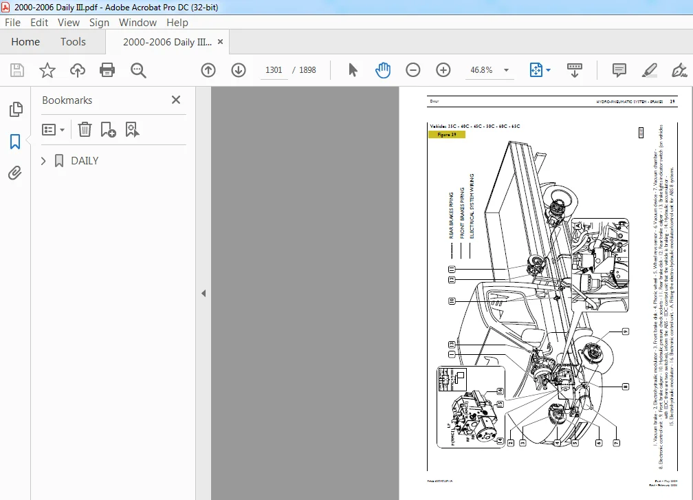
Braking system main components layout 1298
Location of the main brake system components on vehicles with ABS 1300
Location of the main brake system components on vehicles with ESP 1302
DESCRIPTION 1303
Service brake 1303
Emergency brake 1303
Parking brake 1303
BRAKES 1303
Front and Rear disc brakes 1303
FAULT DIAGNOSIS 1304
Diagnosis Instruments 1304
TIGHTENING TORQUES 1312
TOOLS 1314
SPECIFICATIONS AND DATA – HYDRAULIC SYSTEM 1317
SPECIFICATIONS AND DATA – BRAKES 1318
CHECKS 1320
Functional check of vacuum brake system 1320
BRAKING SYSTEM MAIN COMPONENTS 1321
Vacuum pump 1321
Vacuum servo brake 1321
Bleeding air from the hydraulic circuit 1322
Bleeding air from the hydraulic circuit with deaerator device 1322
Air bleeding from the ABS/ESP system hydraulic circuit 1323
Mechanically controlled load sensing valve (vehicles 35C – 40C – 45C – 50C – 60C – 65C) 1325
Regulation of load proportioning valve on vehicle 1325
Dual mechanically controlled load sensing valve (vehicles 29L – 35S) 1326
Adjusting the load sensing valve 1326
STABILITY CONTROL AND ANTI-SKID DEVICES 1327
ABS SYSTEM FUNCTIONS 1327
Antilock braking system (ABS) 1327
Electronic braking distribution device (EBD) 1327
Anti-skid braking device (ABD) 1327
Electronic Stability Program (ESP) – Option 1327
FUNCTIONS INCLUDED IN THE ESP SYSTEM ONLY 1327
Acceleration drive control device (ASR) 1327
Engine braking torque control (MSR) 1327
Hill holder control (HHC) 1327
Hydraulic Brake Assistant (HBA) 1327
Electro-hydraulic modulator/control unit for 29L – 35S vehicles 1328
Electro-hydraulic modulator/control unit for 35C – 65C vehicles 1329
ABS 8/ESP 8 ELECTROHYDRAULIC MODULATOR DIAGRAMS 1330
Hydraulic diagrams of ABS 8 modulator – 4-channel (X) 1331
Hydraulic diagrams of ABS 8 modulator – 3-channel (II) 1335
Pressure increase Hydraulic diagrams of ESP 8 modulator – 4-channel (X) 1339
Hydraulic diagrams of ESP 8 modulator – 4-channel (II) 1348
Rev sensor 1358
Phonic wheels 1358
ESP SYSTEM SENSORS 1358
Yaw sensor with built-in side acceleration sensor 1358
Longitudinal acceleration sensor 1358
Steering angle sensor 1358
BRAKE REPAIRS 1359
Front brakes 1359
Replacing brake linings 1359
Brake caliper removal and refitting 1360
REAR BRAKES 1361
Replacing brake linings 1361
Brake caliper removal and refitting 1363
OVERHAUL OF BRAKE CALIPERS 1363
2×42 – 2×44 – 2×46 – 2x52Brembo brake calipers 1363
1×52 Brembo brake calipers 1364
OVERHAULING BRAKE DISCS 1365
MACHINING AND GRINDING OF DISC BRAKES 1365
WHEEL NUT TIGHTENING SEQUENCE 1366
OVERHAULING PARKING BRAKE 1366
Assembly 1368
Adjusting parking brake 1368
REPLACING THE ESP COMPONENTS 1369
STEERING ANGLE SENSOR 1369
Replacing 1369
Calibration 1369
LONGITUDINAL ACCELERATION SENSOR 1370
Removal 1370
Refitting 1370
Calibration 1370
YAW SENSOR 1371
Removal 1371
Refitting 1371
Calibration 1371
ELECTROHYDRAULIC MODULATOR/CONTROL UNIT 1372
Removal 1372
Refitting 1372
Programming 1372
Calibration 1372
Bench overhauling 1373
Disassembly 1373
Assembly 1373
SECTION 12 – Bodywork – Chassis Frame – Cab air-conditioning 1375
Bodywork – Chassis Frame – Cab air-conditioning 1375
SAFETY STANDARDS TO OBSERVE WHEN WORKING ON VEHICLES EQUIPPEDWITH THE AIR-BAG SYSTEM 1379
CAB AIR-CONDITIONING 1379
General 1379
VENTILATION 1379
Description 1379
AIR-CONDITIONING SYSTEM MAIN COMPONENTS AND FUNCTIONAL DIAGRAM 1380
AIR-CONDITIONING AND HEATING 1380
Description 1380
Air-conditioning 1380
Heating 1380
AUTOMATIC AIR-CONDITIONING/HEATING 1381
Description 1381
MAIN COMPONENTS 1382
Compressor 1382
Condenser 1382
Drier filter 1382
Expansion valve 1383
Evaporator 1383
CONTROL AND SAFETY DEVICES 1384
Description 1384
Three-level pressure switch 1384
Outside air temperature sensor 1384
AIR-CONDITIONING UNIT (“M MARELLI” OR “DENSO” TYPE) 1385
General 1385
Electronic control unit 1385
AIR-CONDITIONING SYSTEM CONTROLS AND LOCATION OF VENTS 1386
HEATER/AIR-CONDITIONER UNIT 1387
Removal and Refitting 1387
Removal 1387
Refitting 1388
“M MARELLI” TYPE HEATER/ AIR-CONDITIONER UNIT 1389
Components 1389
PROCEDURE FOR EMPTYING AND REFILLING THE AIR-CONDITIONING SYSTEMSWITH R134A REFRIGERANT 1391
R134A refrigerant recovery and refilling station (99305146) 1391
CONTROL FASCIA 1392
SAFETY STANDARDS 1394
OPERATION FLOW CHART 1395
RECOVERING REFRIGERANT FROM THE VEHICLE SYSTEM 1396
CREATING A VACUUM IN THE SYSTEM 1398
RESTORING OIL IN THE SYSTEM 1400
FILLING THE SYSTEMWITH REFRIGERANT 1401
CHECKING THE PRESSURES IN THE SYSTEM 1403
OPERATIONS PRIOR TO DISCONNECTING THE STATION FROM THE SYSTEM 1403
LEAK FINDER FOR AIR-CONDITIONING SYSTEMS WITH HFC R134A (9905147) 1403
REPAIRS 1404
Air-conditioner unit control unit 1404
Removal – Refitting 1404
Removal 1404
Refitting 1404
ELECTRONIC CONTROLLER 1404
Removal – Refitting 1404
Removal 1404
Refitting 1404
ANTI-FROST SENSOR 1404
Removal – Refitting 1404
Removal 1404
Refitting 1404
ELECTRIC FAN 1405
Removal – Refitting 1405
Removal 1405
Refitting 1405
HEATER RADIATOR 1405
Removal – Refitting 1405
Removal 1405
Refitting 1405
MIXING ACTIVATOR 1405
Removal – Refitting 1405
Removal 1405
Refitting 1405
AIR INTAKE ACTUATOR 1406
Removal – Refitting 1406
Removal 1406
Refitting 1406
TREATED AIR SENSOR 1406
Removal – Refitting 1406
Removal 1406
Refitting 1406
EVAPORATOR UNIT 1407
Removal – Refitting 1407
Removal 1407
Refitting 1407
EXPANSION VALVE AND EVAPORATOR PIPE 1408
Removal – Refitting 1408
Removal 1408
Refitting 1408
COMPRESSOR 1408
Compressor Removal – Refitting 1408
Removal 1408
Refitting 1408
POLLEN FILTER 1409
Removal – Refitting 1409
Removal 1409
Refitting 1409
THREE-LEVEL PRESSURE SWITCH AND DRIER FILTER 1409
Removal – Refitting 1409
Removal 1409
Refitting 1409
CONDENSER 1409
Removal – Refitting 1409
Removal 1409
Refitting 1409
DIAGNOSTIC 1410
FAILURES OF THE ELECTRIC TYPE (Marelli air-conditioner) 1410
Self-diagnosis 1410
Diagnosis by error codes 1410
Error codes 1412
Diagnosis by IWT, MODUS and UNITESTER 1413
Diagnosis by IWT 1414
FAILURE OF THE MECHANICAL TYPE 1418
“MARELLI” TYPE HEATER 1421
Removal – Refitting 1421
Removal 1421
Refitting 1421
ELECTRIC FAN 1422
Removal – Refitting 1422
Removal 1422
Refitting 1422
HEATER CONTROL CABLES 1423
Removal – Refitting 1423
Removal 1423
Refitting 1423
HEATER UNIT 1424
Components 1424
Passenger s compartment heating and ventilation system 1425
SAFETY STANDARDS TO OBSERVE WHEN WORKING ON VEHICLES EQUIPPEDWITH THE AIR-BAG SYSTEM 1427
PASSENGER S COMPARTMENT HEATING AND VENTILATION SYSTEM 1427
General 1427
VENTILATION 1427
Description 1427
FUNCTIONAL DIAGRAM AND MAIN HEATING AND VENTILATION SYSTEM COMPONENTS 1428
HEATING AND VENTILATION SYSTEM 1428
Description 1428
Air-conditioning 1428
Heating 1428
ADDITIONAL COOLING SYSTEM CONTROLS AND AIR VENTS LAYOUT 1429
DESCRIPTION 1429
ADDITIONAL HEATING SYSTEM CONTROLS 1430
DESCRIPTION 1430
ADDITIONAL COOLING UNIT 1431
Removal – Refitting 1431
Removal 1431
Refitting 1431
ADDITIONAL HEATER UNIT 1432
Removal – Refitting 1432
Removal 1432
Refitting 1432
ADDITIONAL HEATER CIRCUIT ENABLING SOLENOID VALVE 1433
Removal – Refitting 1433
Removal 1433
Refitting 1433
SECTION 13 – Scheduled maintenance 1435
Scheduled maintenance 1435
MAINTENANCE 1437
Table of maintenance services 1437
8140 ENGINE VEHICLES 1437
Inspection and/or maintenance interventions 1438
Extra plan operations 1438
F1A ENGINE VEHICLES 1439
Inspection and/or maintenance interventions 1439
Extra plan operations 1440
F1C ENGINE VEHICLES 1441
Inspection and/or maintenance interventions 1441
Extra plan operations 1442
DIAGRAM OF CHECK AND/OR MAINTENANCE POINTS 1443
MAINTENANCE OPERATIONS 1444
SECTION 14 – Electric/Electronic system 1449
Electric/Electronic system 1449
ABBREVIATIONS AND GRAPHIC SYMBOLS 1455
GENERAL CONDITIONS FOR LAYING ELECTRIC CIRCUITS 1456
GENERAL WARNINGS 1456
TECHNICAL CODES 1457
POWER NETWORK 1461
General 1461
Power network assembly 1462
Positive network 1463
Negative network 1465
Earth points on the vehicle 1467
CONCEPT OF EARTH AND ELECTROMAGNETIC COMPATIBILITY 1468
Practical advice 1469
Ultrasonic cable welding 1470
MAIN COMPONENTS OF POWER NETWORK 1471
BOSCH KCBI 14V 110A Alternator 1471
EV 12V – 2 3 kW Starter motor 1472
Battery 1473
Ignition switch 1474
Interconnection center 1475
General remote control switch (T G C ) 1476
ONBOARD CABLES 1477
Components of the injection system (E 8140) 1477
Engine cable 1477
8140 43C ID/TCA ( 11) ENGINE HARNESS 1478
8140 43S UNIJET ( 13) ENGINE HARNESS 1480
INJECTION CABLE – V G T ( 15) 1482
FIA UNIJET ( 10 – 12) ENGINE HARNESS 1484
F1A UNIJET WITH EDC16 ( 10 – 12 – 14) ENGINE HARNESS 1486
F1C UNIJET WITH EDC16 ( 10 – 12 – 14) ENGINE HARNESS 1488
INJECTION CABLE – FIA ( 10 – 12) WITH AND WITHOUT EGR 1490
TRUCK CHASSIS CABLE 1492
A B S PARALLEL CABLE 1494
AIR-BAG CABLE WITH ONE-CONNECTOR CONTROL UNIT 1496
AIR-BAG CABLE WITH TWO-CONNECTOR CONTROL UNIT 1498
VAN INTERIOR DOME LAMP CABLES 1/2 1500
VAN INTERIOR DOME LAMP CABLES 2/2 1502
TRUCK INTERIOR DOME LAMP CABLES 1504
JUNCTION CONNECTORS 1505
Connection between cab/bonnet cable and injection cable (Unijet) 1505
Connection between cab/bonnet cable and air bag cable 1506
Connection between cab/bonnet cable and rear differential lock cable 1507
Connection between cab/bonnet cable and cable for tachometer 1508
Connection between frame cable and right tail lamp cable 1509
Connection between frame cable and right tail lamp cable 1510
Connection between frame cable and left tail lamp cable 1511
Connection between frame cable and left tail lamp cable 1512
Connection between cab/bonnet cable and roof lamp cable inside cab 1513
Connection between cab/bonnet cable and 13 pin current socket or rear door opening/closing cable (van) 1514
Connection between cab/bonnet cable and brake wear/air cleaner clogged cable 1515
Connection between cab/bonnet cable and self-levelling suspension cable 1516
Connection between cab/bonnet cable and self-levelling suspension cable 1517
Connection between cab/bonnet cable and total power takeoff cable 1518
Connection between cab/bonnet cable and total power takeoff cable 1519
Connection between cab/bonnet cable and antitheft cable 1520
Connection between cab/bonnet cable and antitheft cable with central door locking 1521
Connection between cab/bonnet cable and right door cable 1522
Connection between cab/bonnet cable and left door cable 1523
Connection between cab roof lamp and left front clearance light cable 1524
Connection between cab roof lamp and right front clearance light cable 1525
Connection between cab/bonnet cable and fog lamp cable 1526
Connection between right tail light cable and rear roof lamp cable 1527
Connection between frame cable and side clearance lights cable 1528
Connection between cab/bonnet cable and ABS cable 1529
Connection between cab/bonnet cable and ABS cable 1530
Connection between cab/bonnet cable and climate control system cable 1531
Connection between cab/bonnet cable and climate control system cable 1532
Connection between cab/bonnet cable and climate control system cable 1533
VENDOR-DERIVED BUS VERSION 1534
General Information 1534
Perspective view of Vendor-derived Bus version interior lighting harness 1535
Diagnostic connector 1536
RELAY AND FUSE HOLDER SUPPORT 1538
Identification of fuses 1539
Identification of relays/diode holders 1540
OPTICAL INDICATORS 1541
Interface bride with the new tool with 32-way connectors 1542
INSTRUMENT CLUSTER 1543
Warning lights assembly 1543
Instrument assembly 1544
Connector assembly (cable input side view) 1546
SWITCH ASSEMBLY 1550
STALK UNIT 1552
Functions 1554
Cruise Control 1556
ELECTRONIC SYSTEMS 1557
Immobilizer 1557
System components 1558
Key teaching procedure 1561
ABS/EBD/ABD 1564
General 1564
SYSTEM WITH 4 CROSSED CHANNELS (X) 1568
Location of components 1569
Sensor on phonic wheel 1570
Electrohydraulic control unit/modulator 1571
Electrohydraulic modulator 1572
SYSTEM WITH 4 PARALLEL CHANNELS (11) 1577
Electrohydraulic control unit/modulator 1578
Electrohydraulic modulator 1579
Pressure increase 1579
Electronic control unit 1584
ABS 8/ESP 8 1585
Four crossed channel system (x) 1587
Electro-hydraulic modulator/control unit 1587
Four parallel channel system (II) 1588
Electro-hydraulic modulator/control unit 1588
ABS 8 control unit PIN OUT (X – crossed channels, II – parallel channels) 1589
ESP 8 control unit PIN OUT (X – crossed channels, II – parallel channels) 1590
ESP (Electronic Stability Program) operation 1591
Control strategy 1591
ASR deactivation strategies 1593
Recovery strategy in case of component failure 1593
Warning light legend 1594
Installing the esp components 1594
ESP system components and calibration 1595
Yaw sensor with built-in side acceleration sensor 1595
Steering angle sensor 1597
ESP control unit programming 1598
6AS 300 VD AUTOMATIC TRANSMISSION 1599
Description of operation 1599
Electronic control 1600
COMPOSITION OF THE SYSTEM 1601
System control unit 1601
Connector control unit PIN-OUT – gearbox side (A) 1602
Connector control unit PIN-OUT – vehicle side (B) 1603
Gearbox actuator 1604
Clutch actuator 1606
Display 1608
Gear selector 1609
Accelerator pedal 1610
PTO 1611
DIAGNOSIS INSTRUMENTS 1614
MODUS – IT 2000 – E A SY CONNECTION 1615
TROUBLESHOOTING 1616
ELECTRONIC INJECTION SYSTEM 1621
Common rail 1621
Common rail (F1A) 1623
Hydraulic system (Common Rail – F1A) 1624
SYSTEM COMPONENTS 1625
Camshaft pulley and timing sensor 1625
Flywheel and rpm sensor 1626
Flywheel and camshaft sensor specifications 1627
Pre-filter 1628
Electric pump 1628
Fuel filter 1629
High pressure pump 1630
High-pressure pump (F1IA engine) 1631
Pressure regulator 1632
Pressure regulator (F1A) 1633
Rail (pressure accumulator) 1634
Rail (pressure accumulator – F1A) 1635
Flow limiters 1636
Pressure limiter 1636
Fuel pressure sensor 1636
Injector 1637
Fuel outlets unit 1638
Air flow meter 1639
Atmospheric pressure sensor 1641
Engine coolant temperature sensor 1641
Fuel temperature sensor 1641
Brake pedal switches 1643
Clutch pedal switch 1643
Electromagnetic junction fan 1644
Preheat plug electronic centre (F1A/F1C engine) 1645
Preheat plugs 1645
EDC MS6 3 / EDC16 1646
Electronic injection control 1646
Bosch MS6 3 control unit 1650
Control unit connection to the injection cable on engine side (housing A) 1651
Control unit connection to cab-bonnet cable (housing B) 1652
EDC system components 1653
Blink Code (up to chassis no 5383302/D187233) 1655
Common Rail 8140 43B – 8140 43S – 8140 43N – EDC MS6 3 1655
F1A Common Rail 1656
EDC16 1657
Bosch EDC16 control unit 1658
Control unit connection to the injection cable on engine side (housing A) 1659
Control unit connection to cab-bonnet cable (housing K) 1661
Accelerator pedal sensor 1663
Camshaft sensor (F1A) 1664
Injection cable F1A ( 10 – 12) 1665
Join connector 1668
Diagnostic connector 1669
Diagnostic connector pin description table 1670
High-pressure pump (F1A engine) 1671
F1C ENGINE 1672
Injection cable F1C ( 14 – 17) 1673
Connection between cab/bonnet cable and injection cable 1674
R p m / timing sensors 1675
Timing sensor (stroke) 1676
RPM sensor 1677
Timing sensor 1678
High-pressure pump 1679
Pressure regulator 1680
Rail (pressure accumulator) F1C 1681
Pressure sensor 1681
Air temperature/pressure sensor (without EGR) 1683
Atmospheric pressure sensor 1684
Engine coolant temperature sensor 1684
Fuel temperature sensor 1684
Fuel filter 1685
Brake pedal switches 1686
Clutch pedal switch 1686
Injectors 1687
Electromagnetic junction fan 1688
CLIMATE CONTROL 1689
General 1689
Operating logic 1690
Electronic control unit 1695
Outside air temperature sensor 1696
Inside temperature sensor 1697
Blown air temperature sensor 1698
Evaporator temperature sensor 1698
Required temperature potentiometer 1698
Ventilation control potentiometer 1699
Electronic fan control module 1700
Air mixing gear motor 1701
Re-circulation gear motor 1702
Compressor 1703
Safety pressure switches 1703
SYSTEM SELF-DIAGNOSTIC 1704
Diagnostic through blink code 1704
Blink codes 1705
AIR BAG 1706
General 1706
Operation 1707
Preliminary rules 1708
Operations after an accident 1709
Painting work 1709
Health hazards 1709
Effects of over-exposure 1709
Rules of safety in handling air bag modules 1710
Air bag module scrapping 1710
Rules of safety in handling pretensioners 1711
Scrapping pretensioners 1711
Operations on system components 1712
Removing and scrapping an activated air bag module and pretensioner from a vehicle 1712
Removing or scrapping an air bag module that has not been deployed a reparable vehicle 1712
Deployment of an air bag 1713
Deployment of air bag modules and electronic pretensioners still on board of irreparable vehicles 1714
Electronic control unit 1715
One-connector electronic control unit pin-out 1716
ECU pin-out to the two connectors 1719
Drivers air bag module 1720
Clock spring 1721
Passenger’s air bag module 1723
Pretensioners 1724
Driver’s/passenger’s pretensioner 1725
Centre passenger’s pretensioner 1726
DOOR-BLOCKER WITH ANTI-THEFT PROTECTION 1727
General information 1727
System components 1728
Operation 1729
Arrangement of components 1730
MAIN COMPONENTS OF THE SYSTEM 1731
Remote-control key 1731
Electronic central control unit (ECU) 1733
Arrangement of the switches 1735
Electronic volumetric-detection module 1738
Siren 1739
ERROR CODES 1741
Error code table 1742
AIR SUSPENSIONS ECAS 1743
WABCO electronically controlled air suspensions (ECAS) 1744
Vehicles with braking system without ABS 1746
Vehicles with ABS system 1747
Electronic Control Unit 1748
Level sensor 1750
Pneumatic supply unit 1751
Brake action compensator 1752
Chassis lifting 1754
Chassis lowering 1755
Chassis leveling 1756
VB TECHNIEK PNEUMATIC SUSPENSIONS 1757
Vehicles with braking system without ABS 1759
Vehicles with ABS system 1760
SYSTEM COMPONENTS 1761
Electronic Control Unit (35C – 40C – 45C) 1761
Electronic control unit (60C – 65C – 50C) 1762
Level sensor 1763
Brake action compensator 1764
ROTATING SLIDING DOOR 1765
Description 1765
SYSTEM COMPONENTS 1766
Electronic center 1766
Optical and sound warnings 1768
Sound device 1768
Description and operation 1769
Emergency operation 1770
Diagnosis 1770
Description of opening 1771
Description of closing cycle 1772
Operating diagram 1773
ELECTRONIC TACHOGRAPH 1774
Removing the lower dashboard cover 1774
Electronic tachograph control unit housing assembly 1774
Assembling the tachograph control unit support on the dashboard 1775
Removing the instrument cluster module 1776
Operations on gearbox 1778
Operation in bonnet 1779
CIRCUIT CHARTS 1781
CIRCUIT CHARTS 1785
NOTES AND SPECIFICATIONS 1785
CHART 1A: START 1786
CHART 1B: START ( 10 – 12) 1787
CHART 2A: PREHEATING ( 9) 1788
CHART 2B: PREHEATING ( 11) 1789
CHART 2C: PREHEATING ( 13 – 15) 1790
CHART 2D: PREHEATING ( 10 – 12) 1791
CHART 2E: PRE–HEATING ( 10 – 12 – 14 – 17 – EDC16) 1792
CHART 3: RECHARGE 1793
CHART 4: INSTRUMENTS 1794
CHART 5: TACHOMETER 1795
CHART 6A: RPM COUNTER ( 9) 1796
CHART 6B: RPM COUNTER ( 11) 1797
CHART 6C: RPM COUNTER ( 10 – 12 – 13 – 15) 1798
CHART 6D: RPM COUNTER ( 10 – 12 – 14 – 17 – EDC16) 1799
CHART 7A: OPTICAL INDICATORS ( 9 – 11) 1800
CHART 7B: OPTICAL INDICATORS 1801
CHART 8: OUTSIDE LIGHTING (CAB INSTRUMENTS) 1802
CHART 9A: OUTSIDE LIGHTING (POSITION LIGHTS) 1803
CHART 9B: OUTSIDE LIGHTING (CAB POSITION LIGHTS VAN) 1804
CHART 10: FLOOD AND DIPPED LIGHTS 1805
CHART 11A: BACK AND FRONT FOG LIGHTS 1806
CHART 11B: BACK AND FRONT FOG LIGHTS(VAN) 1807
CHART 12: FRONT LIGHT SETTING 1808
CHART 13A: DIRECTION AND EMERGENCY LIGHTS 1809
CHART 13B: DIRECTION AND EMERGENCY LIGHTS (VAN) 1810
CHART 14A: STOP LIGHTS 1811
CHART 14B: STOP LIGHTS (VAN) 1812
CHART 15A: BACKUP LIGHTS 1813
CHART 15B: BACKUP LIGHTS (VAN) 1814
CHART 16: HORN 1815
CHART 17: WINDSCREEN AND FRONT LIGHTWASHER 1816
CHART 18A: WINDSCREEN DEFROSTER 1817
CHART 18B: WINDSCREEN DEFROSTER ( 10 – 12) 1818
CHART 19: RADIO SET 1819
CHART 20A: INTERNAL LIGHTING AND CIGARETTE LIGHTER 1820
CHART 20B: INTERNAL LIGHTING (VAN) 1821
CHART 20C: INTERNAL LIGHTING 6+1 VEHICLE 1822
CHART 20D: INTERNAL LIGHTING AND CIGARETTE LIGHTER (F1A) 1823
CHART 21A: IMMOBILIZER ( 9) 1824
CHART 21B: IMMOBILIZER ( 11) 1825
CHART 21C: IMMOBILIZER ( 10 – 12 – 13 – 15) 1826
CHART 21D: IMMOBILIZER ( 10 – 12 – 14 – 17 EDC16) 1827
CHART 22A: DIAGNOSIS CONNECTION( 9 – 11) 1828
CHART 22B: DIAGNOSIS CONNECTION( 10 – 12 – 13 – 15 – 14 – 17) 1829
CHART 23A: ENGINE COOLING ( 9) 1830
CHART 23B: ENGINE COOLING ( 11) 1831
CHART 23C: ENGINE COOLING ( 13 – 15) 1832
CHART 23D: ENGINE COOLING ( 10 – 12) 1833
CHART 23E: ENGINE COOLING ( 10 – 12 – 14 – 17 – EDC16) 1834
CHART 24A: EGR/EXHAUST GAS ELECTRONIC CONTROL SYSTEM ( 9) 1835
CHART 24B: EGR/EXHAUST GAS ELECTRONIC CONTROL SYSTEM FOR EDC ( 13) 1836
CHART 24C: EGR/EXHAUST GAS ELECTRONIC CONTROL SYSTEM FOR EDC ( 10 — 12) 1837
CHART 24D: EGR EXHAUST GAS ELECTRONIC CONTROL SYSTEM FOR EDC ( 10 – 12 – 14 – 17 – EDC16) 1838
CHART 25A: SPARK LEAD VARIATOR ( 9) 1839
CHART 25B: SPARK LEAD VARIATOR ( 11) 1840
CHART 26A: E D C ( 13) 1841
CHART 26B: E D C WITH VGT ( 15) 1842
CHART 26C: E D C WITH WASTE GATE ( 13) 1843
CHART 26D: E D C WITHOUT EGR ( 10 – 12) 1844
CHART 26E: E D C WITHOUT EGR ( 10 – 12 – 14 – 17 –EDC16) 1845
CHART 27A: HEATED FUEL FILTER ( 9 – 11) /OPT 2287 1846
CHART 27B: HEATED FUEL FILTER ( 13 – 15) 1847
CHART 27C: HEATED FUEL FILTER ( 10 – 12) 1848
CHART 27D: HEATED FUEL FILTER ( 10 – 12 – 14 – 17 – EDC16) 1849
CHART 28A: POWER WINDOW OPERATOR AND PASSENGER SIDE / OPT 693 1850
CHART 28B: POWER WINDOW OPERATOR SIDE / PASSENGER SIDE ( 10 – 12) 1851
CHART 28C: POWER WINDOW OPERATOR SIDE / OPT 4028 1852
CHART 29: HEATED REARVIEW MIRRORS / OPT 697 1853
CHART 30: REARVIEW MIRROR ADJUSTMENT / OPT 2714 1854
CHART 31: HEATED WINDSCREEN / OPT 685 1855
CHART 32: HEATED REAR WINDOW / OPT 6815 1856
CHART 33: ABS/EBD/ABD / OPT 2091 1857
CHART 34A: E C A S WITHOUT RESERVE AIR RESERVOIR ( 9 – 10 – 11 – 12 – 13 – 14 – 17) 1858
CHART 34B: E C A S WITH RESERVE AIR
RESERVOIR ( 9 – 10 – 11 – 12 – 13 – 14 – 17) 1859
CHART 34C: VB TECHNIEK (35C – 40C – 45C) 1860
CHART 34D: VB TECHNIEK (60C – 65C – 50C) 1861
CHART 35A: AUTOMATIC CONDITIONER ( 9) / OPT 6650 1862
CHART 35B: AUTOMATIC CONDITIONER ( 11) / OPT 6650 1863
CHART 35C: AUTOMATIC CONDITIONER ( 13 – 15) / OPT 6650 1864
CHART 35D: AUTOMATIC CONDITIONER ( 9 – 10 – 11 – 12 – 13 – 14 – 15 – 17) / OPT 6650 1865
CHART 35E: AUTOMATIC CONDITIONER ( 10 – 12) / OPT 6650 1866
CHART 35F: AUTOMATIC AIR CONDITIONING ( 10 – 12 – 14 – 17 – EDC16) 1867
CHART 36: ELECTRONIC TACHOGRAPH / OPT 5130 – 5131 1868
CHART 37A: AIR BAG AND PRE-TENSIONERS / OPT 4495 – 4496 1869
CHART 37B: AIR BAG AND PRETENSIONERS 1870
CHART 38: DOOR LOCK WITH ANTI-THEFT / OPT 6890 1871
CHART 39A: FRONT DIFFERENTIAL LOCK / OPT 131 1872
CHART 39B: REAR DIFFERENTIAL LOCK / OPT 131 1873
CHART 40: 13-POLE POWER CONNECTION / OPT 6520 1874
CHART 41A: TOTAL PTO ( 9 – 11) 1875
CHART 41B: TOTAL PTO ( 10 – 12 – 13 – 15) 1876
CHART 41C: TOTAL PTO (EDC 16) 1877
CHART 42A: HEATED OPERATOR SEAT BUS VERSION /OPT 6628 1878
CHART 42B: HEATED SEATS / OPT 6644 1879
CHART 43: DAY LIGHTS FOR NORTHERN EUROPE VEHICLES / OPT 2536 1880
CHART 44: DOOR LOCK / OPT 6536 1881
CHART 45A: TELMA SCUDATI RETARDER ( 9 – 11) OPT 235 1882
CHART 45B: TELMA RETARDER ( 10 – 12 – 13 – 15) / OPT 235 1883
CHART 46: ELECTRICAL BATTERY SECTIONER / OPT 2532 1884
CHART 47A: CRUISE CONTROL 1885
CHART 47B: CRUISE CONTROL (EDC 16) 1886
CHART 48: ENGINE WATER HEATER / OPT 6654 1887
CHART 49: ELECTRICAL CONTROL SLIDING SIDE DOOR 1888
CHART 50: ROTATING SLIDING DOOR 1889
CHART 51: ELECTRICAL PIT ON PAVILION / OPT 640 1890
CHART 52: SCUDATI CENTRAL EMERGENCY CONTROL / OPT 2546 1891
CHART 53: SYSTEM FOR NORTH AFRICA VEHICLES 1892
CHART 54: SYSTEM FOR BUS VEHICLES WITH 2-TONE HORN 1893
CHART 55: SYSTEM FOR RIGHT HAND DRIVE ROTATING SLIDING DOOR VEHICLES 1894
CHART 56: ABS 8 1895
CHART 57: ESP8 1896
CARD 58: 6 AS 300 VD AUTOMATIC GEARBOX 1897
IMAGES PREVIEW OF THE MANUAL:
PLEASE NOTE:
- This is the same manual used by the dealers to diagnose and troubleshoot your vehicle
- You will be directed to the download page as soon as the purchase is completed. The whole payment and downloading process will take anywhere between 2-5 minutes
- Need any other service / repair / parts manual, please feel free to contact [email protected] . We still have 50,000 manuals unlisted