2000-2010 Suzuki Swift RS415 SERVICE MANUAL – PDF DOWNLOAD
Original price was: $89.00.$29.95Current price is: $29.95.
2000-2010 Suzuki Swift RS415 SERVICE MANUAL – PDF DOWNLOAD
Description
2000-2010 Suzuki Swift RS415 SERVICE MANUAL – PDF DOWNLOAD
IMAGES PREVIEW OF THE MANUAL:
DESCRIPTION:
2000-2010 Suzuki Swift RS415 SERVICE MANUAL – PDF DOWNLOAD
IMPORTANT
WARNING/CAUTION/NOTE
Please read this manual and follow its instructions carefully. To emphasize special information, the words
, and NOTE have special meanings. Pay special attention to the messages highlighted
by these signal words.
WARNING
For vehicles equipped with a Supplemental Restraint (Air Bag) System:
- Service on and around the air bag system components or wiring must be performed only by an authorized SUZUKI dealer. Refer to “Air Bag System Components and Wiring Location View” under “General Description” in air bag system section in order to confirm whether you are performing service on or near the air bag system components or wiring. Please observe all WARNINGS and “Service Precautions” under “On-Vehicle Service” in air bag system section before performing service on or around the air bag system components or wiring. Failure to follow WARNINGS could result in unintentional activation of the system or could render the system inoperative. Either of these two conditions may result in severe injury.
- If the air bag system and another vehicle system both need repair, Suzuki recommends that the air bag system be repaired first, to help avoid unintended air bag system activation.
- Do not modify the steering wheel, instrument panel or any other air bag system component on or around air bag system components or wiring. Modifications can adversely affect air bag system performance and lead to injury.
- If the vehicle will be exposed to temperatures over 93 °C (200 °F), for example, during a paint baking process, remove the air bag system components, that is air bag (inflator) modules, SDM and/or seat belt with pretensioner, beforehand to avoid component damage or unintended activation.
FOREWORD
This manual (Volumes 1 and 2) contains procedures for diagnosis, maintenance, adjustments, minor service
operations, replacement of components (Service) and for disassembly and reassembly of major components
(Unit Repair-Overhaul).
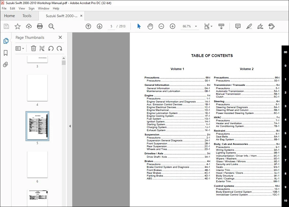
VOLUME 1 contains General information, Engine, Suspension, Drive/Axle and Brakes sections (Sections 0 – 4).
VOLUME 2 contains Transmmision/Transaxle, Steering, HVAC, Restraint, Body/Cab/Accessories and
Control Systems sections (Sections 5 – 10).
Applicable model:
SWIFT (RS415) vehicles on and after following vehicle identification numbers (VINs).
JSAEZC21S00100001
- The contents are classified into sections each of which is given a section number as indicated in the Table of Contents on following page. And on the first page of each individual section is an index of that section.
- This manual should be kept in a handy place for ready reference of the service work. Strict observance of the so specified items will enable one to obtain the full performance of the vehicle. When replacing parts or servicing by disassembling, it is recommended to use SUZUKI genuine parts, tools and service materials as specified in each description.
- All information, illustrations and specifications contained in this literature are based on the latest product information available at the time of publication approval. And used as the main subject of description is the vehicle of standard specifications among others. Therefore, note that illustrations may differ from the vehicle being actually serviced. The right is reserved to make changes at any time without notice
TABLE OF CONTENTS:
2000-2010 Suzuki Swift RS415 SERVICE MANUAL – PDF DOWNLOAD
Suzuki Swift 2005 – 2010 Workshop Manualpdf 2
IMPORTANT 2
FOREWORD 3
TABLE OF CONTENTS 5
Precautions 7
Precautions 8
Precautions 8
Precautions for Vehicles Equipped with a Supplemental Restraint (Air Bag) System 8
General Precautions 10
Precautions for Catalytic Converter 13
Precautions for Installing Mobile Communication Equipment 13
Precaution for CAN Communication System 14
Precautions for Electrical Circuit Service 14
Air Bag Warning 16
Air Bag System Service Warning 16
Fastener Caution 16
Suspension Caution 16
Wheels and Tires Caution 16
Brake Caution 17
Repair Instructions 17
Electrical Circuit Inspection Procedure 17
Intermittent and Poor Connection Inspection 19
General Information 21
General Information 22
General Description 22
Abbreviations 22
Symbols 23
Wire Color Symbols 23
Fasteners Information 24
Vehicle Lifting Points 25
Engine Supporting Points 27
Vehicle Identification Number 28
Engine Identification Number 28
Transmission Identification Number 28
Component Location 28
Warning, Caution and Information Labels Location 28
Maintenance and Lubrication 30
Precautions 30
Precautions for Maintenance and Lubrication 30
Scheduled Maintenance 30
Maintenance Schedule under Normal Driving Conditions 30
Maintenance Recommended under Severe Driving Conditions 31
Repair Instructions 32
Accessory Drive Belt Inspection 32
Accessory Drive Belt Replacement 33
Valve Lash (Clearance) Inspection 33
Engine Oil and Filter Change 33
Engine Coolant Change 34
Exhaust System Inspection 35
Spark Plugs Replacement 35
Air Cleaner Filter Inspection 35
Air Cleaner Filter Replacement 35
Fuel Lines and Connections Inspection 35
Fuel Filter Replacement 36
Fuel Tank Inspection 36
PCV Valve Inspection 36
Fuel Evaporative Emission Control System Inspection 36
Brake Discs and Pads (Front) Inspection 36
Brake Drums and Shoes (Rear) Inspection 36
Brake Hoses and Pipes Inspection 37
Brake Fluid Replacement 37
Brake Lever and Cable Inspection 37
Clutch fluid Inspection 37
Tires Inspection 38
Wheel Discs Inspection 38
Wheel Bearing Inspection 38
Suspension System Inspection 38
Steering System Inspection 38
Drive Shaft (Axle) Boots Inspection 39
Manual Transaxle Oil Inspection 39
Manual Transaxle Oil Replacement 39
Automatic Transaxle Fluid Level Inspection 40
Automatic Transaxle Fluid Replacement 40
Automatic Transaxle Fluid Cooler Hose Inspection 40
All Latches, Hinges and Locks Inspection 40
Air Conditioning Filter (If Equipped) Inspection 41
Air Conditioning Filter (If Equipped) Replacement 41
Final Inspection for Maintenance Service 41
Specifications 42
Tightening Torque Specifications 42
Special Tools and Equipment 42
Recommended Fluids and Lubricants 42
Special Tool 42
Engine 43
Precautions 48
Precautions 48
Precautions for Engine 48
Engine General Information and Diagnosis 49
Precautions 49
Precautions on Engine Service 49
Precautions in Diagnosing Trouble 49
Precautions of ECM Circuit Inspection 49
General Description 50
Statement on Cleanliness and Care 50
Engine Diagnosis General Description 50
On-Board Diagnostic System Description 50
Engine and Emission Control System Description 53
CAN Communication System Description 53
Air Intake System Description 54
Electronic Control System Description 55
Engine and Emission Control Input / Output Table 61
Schematic and Routing Diagram 62
Engine and Emission Control System Diagram 62
Component Location 63
Electronic Control System Components Location 63
Diagnostic Information and Procedures 64
Engine and Emission Control System Check 64
Malfunction Indicator Lamp (MIL) Check 67
DTC Check 67
DTC Clearance 68
DTC Table 68
Fail-Safe Table 72
Scan Tool Data 72
Visual Inspection 76
Engine Basic Inspection 77
Engine Symptom Diagnosis 80
Malfunction Indicator Lamp Does Not Come ON with Ignition Switch ON and Engine Stop (but Engine Can Be Started) 86
Malfunction Indicator Lamp Remains ON after Engine Starts 88
DTC P0010: Camshaft Position Actuator Circuit 90
DTC P0011 / P0012: Camshaft Position – Timing Over-Advanced or System Performance / -Retarded 92
DTC P0031 / P0032: HO2S Heater Control Circuit Low / High (Sensor-1) 94
DTC P0037 / P0038: HO2S Heater Control Circuit Low / High (Sensor-2) 96
DTC P0101: Mass Air Flow Circuit Range / Performance 98
DTC P0102: Mass Air Flow Circuit Low Input 102
DTC P0103: Mass Air Flow Circuit High Input 104
DTC P0106: Manifold Absolute Pressure Range / Performance 106
DTC P0107: Manifold Absolute Pressure Circuit Low Input 108
DTC P0108: Manifold Absolute Pressure Circuit High Input 110
DTC P0111: Intake Air Temperature Circuit Range / Performance 112
DTC P0112: Intake Air Temperature Sensor Circuit Low 115
DTC P0113: Intake Air Temperature Sensor Circuit High 118
DTC P0116: Engine Coolant Temperature Circuit Range / Performance 121
DTC P0117: Engine Coolant Temperature Circuit Low 124
DTC P0118: Engine Coolant Temperature Circuit High 126
DTC P0121: Throttle Position Sensor Circuit Range / Performance 128
DTC P0122: Throttle Position Sensor Circuit Low 133
DTC P0123: Throttle Position Sensor Circuit High 136
DTC P0131 / P0132: O2 Sensor (HO2S) Circuit Low Voltage / High Voltage (Sensor-1) 139
DTC P0133: O2 Sensor (HO2S) Circuit Slow Response (Sensor-1) 142
DTC P0134: O2 Sensor (HO2S) Circuit No Activity Detected (Sensor-1) 143
DTC P0137 / P0138: O2 Sensor (HO2S) Circuit Low Voltage / High Voltage (Sensor-2) 146
DTC P0140: O2 Sensor (HO2S) Circuit No Activity Detected (Sensor-2) 149
DTC P0171 / P0172: Fuel System Too Lean / Rich 151
DTC P0300 / P0301 / P0302 / P0303 / P0304: Random Misfire Detected / Cylinder 1 / Cylinder 2 / Cylinder 3 / Cylinder 4 Misfire Detected 153
DTC P0327 / P0328: Knock Sensor Circuit Low / High 155
DTC P0335: Crankshaft Position (CKP) Sensor Circuit 157
DTC P0340: Camshaft Position (CMP) Sensor Circuit 159
DTC P0401 / P0402: Exhaust Gas Recirculation Flow Insufficient Detected / Excessive Detected 162
DTC P0403: Exhaust Gas Recirculation Control Circuit 165
DTC P0420: Catalyst System Efficiency below Threshold 167
DTC P0443: Evaporative Emission System Purge Control Valve Circuit 169
DTC P0462: Fuel Level Sensor Circuit Low 171
DTC P0463: Fuel Level Sensor Circuit High 173
DTC P0480: Fan 1 (Radiator Cooling Fan) Control Circuit 175
DTC P0500: Vehicle Speed Sensor (VSS) Malfunction 179
DTC P0505: Idle Air Control System 182
DTC P0532: A/C Refrigerant Pressure Sensor Circuit Low 184
DTC P0533: A/C Refrigerant Pressure Sensor Circuit High 186
DTC P0601 / P0602: Internal Control Module Memory Check Sum Error / Control Module Programming Error 188
DTC P0616: Starter Relay Circuit Low 189
DTC P0617: Starter Relay Circuit High 190
DTC P1510: ECM Back-Up Power Supply Malfunction 192
DTC P1603: TCM Trouble Code Detected 193
DTC P1674: CAN Communication (Bus Off Error) 194
DTC P1675: CAN Communication (Transmission Error) 198
DTC P1676: CAN Communication (Reception Error for TCM) 201
DTC P1678: CAN Communication (Reception Error for BCM) 204
DTC P2227 / P2228 / P2229: Barometric Pressure Circuit Malfunction 206
Inspection of ECM and Its Circuits 208
ECM Power and Ground Circuit Check 225
Fuel Injector Circuit Check 228
Fuel Pump and Its Circuit Check 230
Fuel Pressure Check 233
Idle Air Control System Check 234
A/C System Circuits Check 236
Electric Load Signal Circuit Check 240
Radiator cooling fan Low Speed Control System Check 241
Radiator cooling fan High Speed Control System Check 243
Repair Instructions 246
Idle Speed / Idle Air Control (IAC) Duty Inspection 246
Special Tools and Equipment 247
Special Tool 247
Aux Emission Control Devices 248
Diagnostic Information and Procedures 248
EGR System Inspection 248
Repair Instructions 248
EVAP Canister Purge Inspection 248
EVAP Canister Purge Valve and Its Circuit Inspection 248
Vacuum Passage Inspection 249
Vacuum Hose Inspection 250
EVAP Canister Purge Valve Inspection 250
EVAP Canister Inspection 250
EGR Valve Removal and Installation 251
EGR Valve Inspection 251
PCV Hose Inspection 251
PCV Valve Inspection 251
Special Tools and Equipment 252
Special Tool 252
Engine Electrical Devices 253
Repair Instructions 253
Idle Air Control (IAC) Valve Operation Inspection 253
Idle Air Control (IAC) Valve On-Vehicle Inspection 253
Idle Air Control (IAC) Valve Removal and Installation 254
Engine Control Module (ECM) Removal and Installation 254
Manifold Absolute Pressure (MAP) Sensor Inspection 255
Throttle Position (TP) Sensor On-Vehicle Inspection 255
Throttle Position (TP) Sensor Removal and Installation 256
Engine Coolant Temperature (ECT) Sensor Removal and Installation 256
Engine Coolant Temperature (ECT) Sensor Inspection 257
Heated Oxygen Sensor (HO2S-1 and HO2S-2) Heater On-Vehicle Inspection 257
Heated Oxygen Sensor (HO2S-1 and HO2S-2) Removal and Installation 257
Camshaft Position (CMP) Sensor Removal and Installation 258
Camshaft Position (CMP) Sensor Inspection 258
Crankshaft Position (CKP) Sensor Removal and Installation 259
Crankshaft Position (CKP) Sensor Inspection 259
Vehicle Speed Sensor (VSS) Inspection (M/T model) 260
Knock Sensor Removal and Installation 260
Main Relay, Fuel Pump Relay, Starting Motor Control Relay and Throttle Actuator Control Relay Inspection 261
Mass Air Flow (MAF) and Intake Air Temperature (IAT) Sensor On-Vehicle Inspection 261
Mass Air Flow (MAF) and Intake Air Temperature (IAT) Sensor Removal and Installation 262
Mass Air Flow (MAF) and Intake Air Temperature (IAT) Sensor Inspection 262
Specifications 263
Tightening Torque Specifications 263
Special Tools and Equipment 263
Special Tool 263
Engine Mechanical 264
General Description 264
Engine Construction Description 264
Camshaft Position Control (VVT Variable Valve Timing) System Description 264
Diagnostic Information and Procedures 267
Compression Check 267
Engine Vacuum Check 268
Valve Lash (Clearance) Inspection 269
Repair Instructions 271
Air Cleaner Element Removal and Installation 271
Air Cleaner Element Inspection and Cleaning 272
Cylinder Head Cover Removal and Installation 272
Accelerator Cable Adjustment 274
Throttle Body Components 274
Throttle Body On-Vehicle Inspection 275
Throttle Body Removal and Installation 275
Throttle Body Cleaning 276
Throttle Body and Intake Manifold Components 277
Intake Manifold Removal and Installation 278
Engine Mountings Components 279
Engine Assembly Removal and Installation 280
Timing Chain Cover Components 283
Timing Chain Cover Removal and Installation 284
Timing Chain Cover Inspection 286
Oil Control Valve Removal and Installation 286
Oil Control Valve Inspection 287
Timing Chain and Chain Tensioner Components 287
Timing Chain and Chain Tensioner Removal and Installation 288
Timing Chain and Chain Tensioner Inspection 290
Camshaft, Tappet and Shim Components 291
Camshaft, Tappet and Shim Removal and Installation 292
Camshaft, Tappet and Shim Inspection 294
Valves and Cylinder Head Components 297
Valves and Cylinder Head Removal and Installation 298
Valves and Cylinder Head Disassembly and Assembly 300
Valves and Valve Guides Inspection 302
Cylinder Head Inspection 305
Valve Spring Inspection 305
Pistons, Piston Rings, Connecting Rods and Cylinders Components 306
Pistons, Piston Rings, Connecting Rods and Cylinders Removal and Installation 307
Pistons, Piston Rings, Connecting Rods and Cylinders Disassembly and Assembly 308
Cylinders, Pistons and Piston Rings Inspection 309
Piston Pins and Connecting Rods Inspection 311
Crank Pin and Connecting Rod Bearings Inspection 312
Main Bearings, Crankshaft and Cylinder Block Components 316
Main Bearings, Crankshaft and Cylinder Block Removal and Installation 317
Crankshaft Inspection 319
Main Bearings Inspection 321
Sensor Plate Inspection 326
Rear Oil Seal Inspection 326
Flywheel Inspection 326
Cylinder Block Inspection 326
Specifications 327
Tightening Torque Specifications 327
Special Tools and Equipment 328
Recommended Service Material 328
Special Tool 328
Engine Lubrication System 330
General Description 330
Engine Lubrication Description 330
Diagnostic Information and Procedures 332
Oil Pressure Check 332
Repair Instructions 333
Oil Pan and Oil Pump Strainer Components 333
Oil Pan and Oil Pump Strainer Removal and Installation 334
Oil Pan and Oil Pump Strainer Cleaning 335
Oil Pump Components 336
Oil Pump Removal and Installation 336
Oil Pump Disassembly and Reassembly 336
Oil Pump Inspection 337
Specifications 339
Tightening Torque Specifications 339
Special Tools and Equipment 339
Recommended Service Material 339
Special Tool 339
Engine Cooling System 340
General Description 340
Cooling System Description 340
Coolant Description 340
Schematic and Routing Diagram 341
Coolant Circulation 341
Diagnostic Information and Procedures 342
Engine Cooling Symptom Diagnosis 342
Repair Instructions 343
Cooling System Components 343
Coolant Level Check 344
Engine Cooling System Inspection and Cleaning 344
Cooling System Draining 344
Cooling System Flush and Refill 345
Cooling Water Pipes or Hoses Removal and Installation 346
Thermostat Removal and Installation 346
Thermostat Inspection 347
Radiator Cooling Fan Motor On-Vehicle Inspection 347
Radiator Cooling Fan Relay Inspection 348
Radiator Cooling Fan Removal and Installation 348
Radiator On-Vehicle Inspection and Cleaning 348
Radiator Removal and Installation 349
Water Pump / Generator Drive Belt Tension Inspection and Adjustment 349
Water Pump / Generator Drive Belt Removal and Installation 350
Water Pump Removal and Installation 350
Water Pump Inspection 351
Specifications 351
Tightening Torque Specifications 351
Special Tools and Equipment 351
Recommended Service Material 351
Fuel System 352
Precautions 352
Precautions on Fuel System Service 352
General Description 352
Fuel System Description 352
Fuel Delivery System Description 352
Fuel Pump Description 353
Schematic and Routing Diagram 353
Fuel Delivery System Diagram 353
Diagnostic Information and Procedures 353
Fuel Pressure Inspection 353
Fuel Cut Operation Inspection 354
Repair Instructions 355
Fuel System Components 355
Fuel Hose Disconnecting and Reconnecting 356
Fuel Pressure Relief Procedure 358
Fuel Leakage Check Procedure 358
Fuel Lines On-Vehicle Inspection 358
Fuel Pipe Removal and Installation 358
Fuel Injector On-Vehicle Inspection 359
Fuel Injector Removal and Installation 359
Fuel Injector Inspection 360
Fuel Filler Cap Inspection 361
Fuel Tank Inlet Valve Removal and Installation 362
Fuel Tank Inlet Valve Inspection 363
Fuel Tank Removal and Installation 363
Fuel Tank Inspection 364
Fuel Tank Purging Procedure 364
Fuel Pump On-Vehicle Inspection 365
Fuel Pump Assembly Removal and Installation 365
Fuel Level Sensor Removal and Installation 366
Fuel Pump Inspection 367
Specifications 367
Tightening Torque Specifications 367
Special Tools and Equipment 368
Special Tool 368
Ignition System 369
General Description 369
Ignition System Construction 369
Schematic and Routing Diagram 370
Ignition System Wiring Circuit Diagram 370
Component Location 371
Ignition System Components Location 371
Diagnostic Information and Procedures 372
Ignition System Symptom Diagnosis 372
Reference Waveform of Ignition System 372
Ignition System Check 373
Ignition Spark Test 374
Repair Instructions 375
High-Tension Cord Removal and Installation 375
High-Tension Cord Inspection 375
Spark Plug Removal and Installation 376
Spark Plug Inspection 376
Ignition Coil Assembly (Including ignitor) Removal and Installation 376
Ignition Coil Assembly (Including ignitor) Inspection 377
Ignition Timing Inspection 377
Specifications 378
Tightening Torque Specifications 378
Special Tools and Equipment 378
Special Tool 378
Starting System 379
Schematic and Routing Diagram 379
Cranking System Circuit Diagram 379
Diagnostic Information and Procedures 379
Cranking System Symptom Diagnosis 379
Cranking System Test 381
Repair Instructions 382
Starting Motor Dismounting and Remounting 382
Starting Motor Components 383
Starting Motor Inspection 384
Specifications 387
Cranking System Specifications 387
Tightening Torque Specifications 387
Special Tools and Equipment 387
Recommended Service Material 387
Charging System 388
General Description 388
Battery Description 388
Generator Description 389
Diagnostic Information and Procedures 390
Battery Inspection 390
Generator Symptom Diagnosis 390
Generator Test (Undercharged Battery Check) 391
Generator Test (Overcharged Battery Check) 392
Repair Instructions 393
Jump Starting in Case of Emergency 393
Battery Dismounting and Remounting 393
Generator Dismounting and Remounting 394
Generator Components 395
Generator Inspection 396
Specifications 398
Charging System Specifications 398
Tightening Torque Specifications 398
Exhaust System 399
General Description 399
Exhaust System Description 399
Diagnostic Information and Procedures 399
Exhaust System Check 399
Repair Instructions 400
Exhaust System Components 400
Exhaust Manifold Removal and Installation 401
Exhaust Pipe and Muffler Removal and Installation 402
Specifications 403
Tightening Torque Specifications 403
Suspension 405
Precautions 407
Precautions 407
Precautions on Suspension 407
Suspension General Diagnosis 408
Diagnostic Information and Procedures 408
Suspension, Wheels and Tires Symptom Diagnosis 408
Specifications 410
Wheel Alignment Specifications 410
Front Suspension 411
General Description 411
Front Suspension Construction 411
Front Wheel Alignment Construction 412
Repair Instructions 412
Front Wheel Alignment Inspection and Adjustment 412
Front Strut Assembly Components 414
Front Strut Assembly Removal and Installation 414
Front Strut Assembly Disassembly and Assembly 416
Front Strut Assembly Check 417
Front Wheel Hub and Steering Knuckle Components 418
Front Wheel Hub, Steering Knuckle and Wheel Bearing Removal and Installation 418
Front Wheel Hub, Disc, Nut and Bearing Check 422
Suspension Control Arm / Bushing Removal and Installation 422
Suspension Control Arm / Bushing Disassembly and Assembly 423
Suspension Control Arm / Steering Knuckle Check 424
Suspension Control Arm Bushing Check 424
Suspension Control Arm Joint Check 424
Front Suspension Frame, Stabilizer Bar and/or Bushings Components 425
Front Suspension Frame, Stabilizer Bar and/or Bushings Removal and Installation 425
Front Suspension Frame Check 428
Front Stabilizer Bar, Bushing and/or Joint Check 429
Front Suspension Fasteners Check 429
Specifications 429
Tightening Torque Specifications 429
Special Tools and Equipment 430
Special Tool 430
Rear Suspension 431
General Description 431
Rear Suspension Construction 431
Component Location 432
Rear Suspension Component Location 432
Repair Instructions 433
Rear Shock Absorber Removal and Installation 433
Rear Shock Absorber Inspection 434
Rear Shock Absorber Bush Removal and Installation 434
Rear Shock Absorber Bush Inspection 435
Coil Spring Removal and Installation 435
Spring Upper Seat / Spring Lower Seat Inspection 436
Spring Upper Seat and Lower Seat Removal and Installation 436
Rear Axle Removal and Installation 437
Trailing Arm, Rear Axle and Coil Spring Inspection 440
Rear Axle Bush Inspection 440
Wheel Bearing and Wheel Stud Bolt Removal and Installation 441
Rear Wheel Disc, Nut and Bearing Inspection 442
Spindle Removal and Installation 442
Spindle Inspection 443
Rear Suspension Fasteners Inspection 443
Specifications 444
Tightening Torque Specifications 444
Special Tools and Equipment 444
Special Tool 444
Wheels and Tires 445
General Description 445
Tires Description 445
Wheels Description 446
Irregular and/or Premature Wear Description 446
Wear Indicators Description 447
Radial Tire Waddle Description 447
Radial Tire Lead / Pull Description 448
Balancing Wheels Description 448
Repair Instructions 449
General Balance Procedures 449
Tire Rotation 449
Wheel Removal and Installation 450
Tire Mounting and Dismounting 450
Tire Repair 450
Specifications 451
Wheels and Tires Specifications 451
Tightening Torque Specifications 451
Driveline / Axle 453
Drive Shaft / Axle 454
General Description 454
Front Drive Shaft Construction 454
Component Location 454
Front Drive Shaft Assembly Components Location 454
Diagnostic Information and Procedures 455
Front Drive Shaft Symptom Diagnosis 455
Repair Instructions 455
Front Drive Shaft Components 455
Front Drive Shaft Assembly On-Vehicle Inspection 456
Front Drive Shaft Assembly Removal and Installation 456
Front Drive Shaft Disassembly and Assembly 457
Center Shaft and Center Bearing Support Disassembly and Assembly 460
Front Drive Shaft Inspection 462
Specifications 462
Tightening Torque Specifications 462
Special Tools and Equipment 463
Recommended Service Material 463
Special Tool 463
Brakes 465
Precautions 467
Precautions 467
Precautions for Brakes 467
Brake Control System and Diagnosis 468
Precautions 468
Precautions on Brake 468
General Description 468
Brakes Construction 468
Front Brake Hose / Pipe Construction 469
Rear Brake Hose / Pipe Construction 470
Diagnostic Information and Procedures 470
Brakes Diagnosis Note 470
Brakes Symptom Diagnosis 471
Repair Instructions 473
Brake Pedal Free Height Inspection 473
Brake Pedal Play Inspection 473
Excessive Pedal Travel Inspection 473
Master Cylinder and Brake Fluid Level Inspection 474
Stop Light Switch Adjustment 474
Air Bleeding of Brake System 474
Front Brake Hose / Pipe Removal and Installation 475
Rear Brake Hose / Pipe Removal and Installation 476
Brake Hose and Pipe Inspection 476
Master Cylinder Components 476
Master Cylinder Reservoir Removal and Installation 477
Master Cylinder Assembly Removal and Installation 478
Master Cylinder Assembly Disassembly and Assembly 479
Master Cylinder Assembly Inspection 480
Brake Booster Components 480
Booster Operation Inspection 481
Brake Booster Removal and Installation 482
Brake Booster Inspection and Adjustment 483
Specifications 483
Tightening Torque Specifications 483
Special Tools and Equipment 483
Recommended Service Material 483
Front Brakes 484
Repair Instructions 484
Front Disc Brake Components 484
Front Disc Brake Pad On-Vehicle Inspection 485
Front Disc Brake Pad Removal and Installation 485
Front Disc Brake Pad Inspection 486
Front Disc Brake Caliper Removal and Installation 486
Front Disc Brake Caliper Disassembly and Assembly 487
Front Disc Brake Caliper Inspection 489
Front Brake Disc Removal and Installation 489
Front Brake Disc Inspection 490
Specifications 491
Tightening Torque Specifications 491
Special Tools and Equipment 491
Recommended Service Material 491
Special Tool 491
Rear Brakes 492
Repair Instructions 492
Rear Drum Brake Components 492
Rear Brake Drum Removal and Installation 492
Rear Brake Drum and Shoe Inspection 494
ABS Sensor Ring Removal and Installation (If Equipped) 494
ABS Sensor Ring Inspection 495
Rear Brake Shoe Removal and Installation 495
Rear Brake Shoe Inspection 496
Wheel Cylinder Removal and Installation 496
Wheel Cylinder Inspection 497
Brake Back Plate Removal and Installation 497
Specifications 499
Tightening Torque Specifications 499
Special Tools and Equipment 499
Recommended Service Material 499
Special Tool 499
Parking Brake 500
General Description 500
Parking Brake Cable Construction 500
Repair Instructions 501
Parking Brake Inspection and Adjustment 501
Parking Brake Cable Removal and Installation 502
Parking Brake Lever Removal and Installation 502
Specifications 503
Tightening Torque Specifications 503
ABS 504
Precautions 504
Precautions in Diagnosing Troubles 504
Precautions in On-Vehicle Service 504
General Description 505
ABS Description 505
ABS Hydraulic Unit / Control Module Assembly Description 505
Schematic and Routing Diagram 506
ABS Schematic 506
ABS Wiring Circuit Diagram 507
Component Location 508
ABS Components Location 508
Front Wheel Speed Sensor Components Location 509
Rear Wheel Speed Sensor Components Location 509
Diagnostic Information and Procedures 510
ABS Check 510
ABS Warning Lamp Check 512
EBD Warning Lamp (Brake Warning Lamp) Check 512
DTC Check 512
DTC Table 513
DTC Clearance 513
Scan Tool Data 513
ABS Warning Lamp Does Not Come ON at Ignition Switch ON 514
ABS Warning Lamp Comes ON Steady 515
ABS Warning Lamp Flashes Continuously while Ignition Switch Is ON 517
EBD Warning Lamp (Brake Warning Lamp) Comes ON Steady 518
Serial Data Link Circuit Check 519
DTC C1021, C1022 / C1025, C1026 / C1031, C1032 / C1035, C1036: Right-Front / Left-Front / Right- Rear / Left-Rear Wheel Speed Sensor Circuit or Sensor Ring 521
DTC C1041 / C1045 / C1051 / C1055, DTC C1042 / C1046 / C1052 / C1056: Right-Front / Left-Front / Right-Rear / Left-Rear Inlet Solenoid Circuit, Right-Front / Left-Front / Right-Rear / Left-Rear Outlet Solenoid Circuit 523
DTC C1057: Power Source Circuit 524
DTC C1061: ABS Pump Motor and/or Motor Driver Circuit 525
DTC C1063: Solenoid Valve Power Supply Driver Circuit 526
DTC C1071: ABS Control Module 527
Repair Instructions 528
ABS Hydraulic Unit Operation Check 528
ABS Hydraulic Unit / Control Module Assembly Components 528
ABS Hydraulic Unit / Control Module Assembly On-Vehicle Inspection 529
ABS Hydraulic Unit / Control Module Assembly Removal and Installation 529
Front Wheel Speed Sensor On-Vehicle Inspection 531
Front Wheel Speed Sensor Removal and Installation 531
Front Wheel Speed Sensor Inspection 532
Rear Wheel Speed Sensor On-Vehicle Inspection 532
Rear Wheel Speed Sensor Removal and Installation 533
Rear Wheel Speed Sensor Inspection 534
Front Wheel Speed Sensor Ring On-Vehicle Inspection 534
Front Wheel Speed Sensor Ring Removal and Installation 535
Rear Wheel Speed Sensor Ring On-Vehicle Inspection 535
Rear Wheel Speed Sensor Ring Removal and Installation 535
Specifications 535
Tightening Torque Specifications 535
Special Tools and Equipment 536
Special Tool 536
Transmission / Transaxle 537
Precautions 540
Precautions 540
Precautions on Transmission / Transaxle 540
Automatic Transmission 541
Precautions 541
Precautions in Diagnosing Trouble 541
Precautions for Disassembly and Reassembly 541
General Description 543
A/T Description 543
Clutch / Brake / Planetary Gear Function of Automatic Transaxle 546
Table of Component Operation 546
A/T Diagnosis General Description 547
On-Board Diagnostic System Description 547
CAN Communication System Description 548
Schematic and Routing Diagram 549
Transmission Control Module (TCM) Wiring Diagram 549
Automatic Gear Shift Table 551
Component Location 552
Electronic Shift Control System Components Location 552
Diagnostic Information and Procedures 554
A/T System Check 554
Visual Inspection 557
Malfunction Indicator Lamp (MIL) Check 557
DTC Table 557
DTC Check 559
DTC Clearance 559
Fail-Safe Table 560
Scan Tool Data 562
A/T Basic Check 565
Road Test 566
Manual Road Test 568
Engine Brake Test 569
Stall Test 569
Time Lag Test 571
Line Pressure Test 572
“P? Range Test 573
A/T Symptom Diagnosis 573
No Gear Shift to 4th gear 581
No Lock-Up Occurs 582
DTC P0705: Transmission Range Sensor Circuit Malfunction 583
DTC P0707: Transmission Range Sensor Circuit Low 585
DTC P0712: Transmission Fluid Temperature Sensor Circuit Low 587
DTC P0713: Transmission Fluid Temperature Sensor Circuit High 588
DTC P0717: Input / Turbine Speed Sensor Circuit Malfunction 589
DTC P0722: Output Speed Sensor (VSS) Circuit No Signal 591
DTC P0741 / P0742: TCC Circuit Performance or Stuck OFF / TCC Circuit Stuck ON 593
DTC P0751 / P0752 / P0756 / P0757: Shift Solenoid Malfunction 594
DTC P0787: Shift / Timing Solenoid Control Circuit Low 595
DTC P0788: Shift / Timing Solenoid Control Circuit High 597
DTC P0962: Pressure Control Solenoid Control Circuit Low 599
DTC P0963: Pressure Control Solenoid Control Circuit High 601
DTC P0973 / P0976: Shift Solenoid-A (No1) Control Circuit Low / Shift Solenoid-B (No2) Control Circuit Low 603
DTC P0974 / P0977: Shift Solenoid-A (No1) / Shift Solenoid-B (No2) Control Circuit High 605
DTC P1702: Internal Control Module Memory Check Sum Error 607
DTC P1703: Can Invalid Data – TCM 607
DTC P1723: Range Select Switch Malfunction 608
DTC P1774: Control Module Communication Bus Off 609
DTC P1775: High Speed CAN Communication Bus Off (Transmission Error) 612
DTC P1777: TCM Lost Communication with ECM (Reception Error) 615
DTC P1778: TCM Lost Communication with BCM (Reception Error) 618
DTC P1878: Torque Converter Clutch Shudder 621
DTC P2763: Torque Converter Clutch (TCC) Pressure Control Solenoid Control Circuit High 622
DTC P2764: Torque Converter Clutch (TCC) Circuit Pressure Control Solenoid Control Circuit Low 624
Inspection of TCM and Its Circuits 626
TCM Power and Ground Circuit Check 630
Brake Interlock System Inspection 631
Repair Instructions 632
Learning Control Initialization 632
A/T Fluid Level Check 632
A/T Fluid Change 633
Selector Lever Components 633
Select Lever Assembly Installation 634
Select Lever Knob Installation 634
Selector Lever Inspection 634
Select Cable Components 634
Select Cable Removal and Installation 635
Select Cable Adjustment 635
Transmission Range Sensor (Shift Switch) Inspection and Adjustment 636
Output Shaft Speed Sensor (VSS) Removal and Installation 636
Output Shaft Speed Sensor (VSS) Inspection 637
Input Shaft Speed Sensor Removal and Installation 637
Input Shaft Speed Sensor Inspection 637
Transmission Fluid Temperature Sensor Removal and Installation 638
Transmission Fluid Temperature Sensor Inspection 638
“3? Position Switch Inspection 639
Solenoid Valves (Shift Solenoid Valves and Timing Solenoid Valve) Removal and Installation 639
Solenoid Valves (Shift Solenoid Valves, and Timing Solenoid Valve) Inspection 640
Pressure Control Solenoid Valves (Pressure Control Solenoid and TCC Pressure Control Solenoid) Removal and Installation 642
Pressure Control Solenoid Valve Inspection 642
Transmission Control Module (TCM) Removal and Installation 643
A/T Relay Inspection 644
Differential Side Oil Seal Replacement 644
Shift Lock Solenoid Inspection 645
Shift Lock Solenoid Replacement 645
Key Interlock Cable Removal and Installation 646
A/T Fluid Cooler Hoses Replacement 647
Automatic Transaxle Unit Components 647
Automatic Transaxle Unit Dismounting and Remounting 648
Automatic Transaxle Assembly Components 650
Automatic Transaxle Unit Disassembly 652
Oil Pump Assembly Components 663
Oil Pump Assembly Disassembly and Reassembly 664
Oil Pump Assembly Inspection 664
Direct Clutch Assembly Components 666
Direct Clutch Assembly Preliminary Check 666
Direct Clutch Assembly Disassembly and Reassembly 667
Direct Clutch Assembly Inspection 669
Forward and Reverse Clutch Assembly Components 670
Forward and Reverse Clutch Assembly Preliminary Check 670
Forward and Reverse Clutch Assembly Disassembly and Reassembly 671
Forward and Reverse Clutch Assembly Inspection 674
2nd Brake Piston Assembly Components 675
2nd Brake Piston Assembly Disassembly and Reassembly 675
Transaxle Rear Cover (O/D and 2nd Coast Brake Piston) Assembly Components 676
Transaxle Rear Cover (O/D and 2nd Coast Brake Piston) Assembly Disassembly and Reassembly 677
Transaxle Rear Cover (O/D and 2nd Coast Brake Piston) Assembly Inspection 678
Countershaft Assembly Components 679
Countershaft Assembly Disassembly and Reassembly 679
Valve Body Assembly Components 680
Valve Body Assembly Disassembly and Reassembly 681
Differential Assembly Components 682
Differential Assembly Disassembly and Reassembly 683
Differential Assembly Inspection 684
Torque Converter Housing Disassembly and Reassembly 685
Transaxle Case Disassembly and Reassembly 687
Automatic Transaxle Unit Inspection and Adjustment 688
Automatic Transaxle Unit Assembly 690
Specifications 706
Tightening Torque Specifications 706
Special Tools and Equipment 707
Recommended Service Material 707
Special Tool 707
Manual Transmission 710
General Description 710
Manual Transaxle Construction and Servicing 710
Diagnostic Information and Procedures 712
Manual Transaxle Symptom Diagnosis 712
Repair Instructions 712
Manual Transaxle Oil Change 712
Differential Side Oil Seal Replacement 713
Gear Shift Control Lever and Cable Components 714
Gear Shift Control Lever and Cable Removal and Installation 715
Gear Select Control Cable Adjustment 715
Vehicle Speed Sensor (VSS) Removal and Installation 716
Back Up Lamp Switch Removal and Installation 716
Back Up Lamp Switch Inspection 717
Manual Transaxle Unit Components 717
Manual Transaxle Unit Dismounting and Remounting 718
Gear Shift and Select Shaft Assembly Components 720
Gear Shift and Select Shaft Assembly Removal and Installation 720
Gear Shift and Select Shaft Disassembly and Assembly 721
Manual Transaxle Assembly Components 722
Fifth Gear Disassembly and Assembly 723
Manual Transaxle Assembly Disassembly and Reassembly 726
Transaxle Right Case Disassembly and Assembly 731
Transaxle Left Case Disassembly and Assembly 732
Input Shaft and Countershaft Components 733
Input Shaft Assembly Disassembly and Reassembly 734
Countershaft Assembly Disassembly and Reassembly 736
Synchronizer Parts Inspection 739
Gear Shift Shaft Components 739
5th and Reverse Gear Shift Shafts Disassembly and Assembly 740
Gear Shift Shaft and Fork Inspection 740
Differential Components 741
Differential Disassembly and Assembly 741
Specifications 743
Tightening Torque Specifications 743
Special Tools and Equipment 744
Recommended Service Material 744
Special Tool 744
Clutch 747
General Description 747
Clutch Construction 747
Diagnostic Information and Procedures 748
Clutch System Symptom Diagnosis 748
Repair Instructions 749
Clutch Pedal Inspection 749
Clutch Fluid Level Inspection 750
Air Bleeding of Clutch System 750
Clutch Fluid Pipe and Hose Components 751
Clutch Fluid Pipe Removal and Installation 751
Clutch Fluid Pipe Inspection 752
Clutch Master Cylinder Removal and Installation 752
Clutch Operating Cylinder Removal and Installation 752
Clutch Pedal and Clutch Pedal Bracket Components 753
Clutch Cover, Clutch Disc and Flywheel Components 754
Clutch Cover, Clutch Disc and Flywheel Removal and Installation 754
Clutch Cover, Clutch Disc and Flywheel Inspection 756
Clutch Release System Removal and Installation 756
Clutch Release System Inspection 758
Specifications 758
Tightening Torque Specifications 758
Special Tools and Equipment 759
Recommended Service Material 759
Special Tool 759
Steering 761
Precautions 763
Precautions 763
Precautions on Steering 763
Steering General Diagnosis 764
Precautions 764
Precautions for Steering Diagnosis 764
Diagnostic Information and Procedures 765
Steering Symptom Diagnosis 765
Steering Wheel and Column 766
Precautions 766
Service Precautions of Steering Wheel and Column 766
Diagnostic Information and Procedures 766
Checking Steering Column for Accident Damage 766
Repair Instructions 767
Steering Wheel and Column Construction 767
Steering Wheel Removal and Installation 767
Contact Coil Cable Assembly Removal and Installation 768
Centering Contact Coil Cable Assembly 769
Contact Coil Cable Assembly Inspection 770
Steering Column Removal and Installation 770
Steering Column Inspection 772
Steering Lower Shaft Removal and Installation 772
Specifications 773
Tightening Torque Specifications 773
Special Tools and Equipment 773
Special Tool 773
Power Assisted Steering System 774
Precautions 774
Steering System Note 774
Precautions in Diagnosing Troubles 774
General Description 774
P/S System Description 774
EPS Diagnosis General Description 775
On-Board Diagnostic System Description 775
Schematic and Routing Diagram 776
EPS System Wiring Circuit Diagram 776
Diagnostic Information and Procedures 777
EPS System Check 777
“EPS? Warning Lamp Check 778
DTC Check 779
DTC Clearance 779
DTC Table 779
Scan Tool Data 781
P/S System Symptom Diagnosis 782
Serial Data Link Circuit Check 782
“EPS? Warning Lamp Does Not Come ON at Ignition Switch ON but Engine Stop 784
“EPS? Warning Lamp Come ON Steady and Engine Start 786
DTC C1113 / C1117 /C1118: Torque Sensor Circuit Failure 787
DTC C1114: Torque Sensor 5 V Power Supply Circuit Failure 788
DTC C1119: Torque Sensor 12 V Power Supply Circuit Failure 790
DTC C1121 / C1123 / C1124: VSS Circuit Failure 792
DTC C1122: Engine Speed Signal Circuit Failure 794
DTC C1141 / C1142 / C1143 / C1145: Motor Circuit Failure 795
DTC C1153: P/S Control Module Power Supply Circuit Failure 796
DTC C1155: P/S Control Module Failure 798
Inspection of P/S Control Module and Its Circuits 798
Steering Wheel Play Check 801
Steering Force Check 801
Repair Instructions 802
Steering Gear Case Assembly Components 802
Tie-Rod End Boot On-Vehicle Inspection 803
Tie-Rod End Removal and Installation 803
Tie-Rod End Inspection 804
Steering Shaft Joint On-Vehicle Inspection 804
Steering Gear Case Assembly Removal and Installation 804
Steering Rack Boot Inspection 806
Tie-Rod / Rack Boot Removal and Installation 806
Steering Rack Plunger Removal and Installation 808
Steering Rack Plunger Inspection 808
P/S Control Module Removal and Installation 808
Torque Sensor Inspection 809
Motor Assembly Inspection 809
Specifications 810
Tightening Torque Specifications 810
Special Tools and Equipment 811
Recommended Service Material 811
Special Tool 811
HVAC 813
Precautions 814
Precautions 814
Precautions on HVAC 814
Heater and Ventilation 815
General Description 815
Heater and Ventilation Construction 815
Schematic and Routing Diagram 816
Heater and Ventilation Wiring Circuit Diagram 816
Diagnostic Information and Procedures 817
Heater and Ventilation Symptom Diagnosis 817
Repair Instructions 818
HVAC Unit Components 818
HVAC Unit Removal and Installation 819
Blower Motor Removal and Installation 819
Blower Motor Inspection 819
Blower Motor Resistor Removal and Installation 820
Blower Motor Resistor Inspection 820
HVAC Control Unit Components 821
HVAC Control Unit Removal and Installation 821
Blower Speed Selector Inspection 822
Air Intake Switch Inspection 823
Air Intake Control Actuator Removal and Installation 823
Air Intake Control Actuator Inspection 823
Center Ventilation Louver Removal and Installation 824
Side Ventilation Louver Removal and Installation 824
Air Filter Removal and Installation 825
Air Filter Cleaning 825
Air Conditioning System 826
Precautions 826
A/C System Caution 826
Precautions on Servicing A/C System 826
General Description 828
Refrigerant Type Construction 828
Sub-Cool A/C System Description 828
Schematic and Routing Diagram 830
Major Components of A/C System 830
A/C System Wiring Diagram 831
Diagnostic Information and Procedures 832
A/C System Symptom Diagnosis 832
Abnormal Noise Symptom Diagnosis of A/C System 834
A/C System Performance Inspection 835
A/C System Inspection at ECM 840
Repair Instructions 842
Operation Procedure for Refrigerant Charge 842
Condenser Assembly On-Vehicle Inspection 847
Condenser Assembly Removal and Installation 847
Desiccant Removal and Installation 848
HVAC Unit Components 849
HVAC Unit Removal and Installation 850
Evaporator Inspection 850
Evaporator Thermistor (Evaporator Temperature Sensor) Removal and Installation 850
Evaporator Thermistor (Evaporator Temperature Sensor) Inspection 851
Expansion Valve Removal and Installation 851
Expansion Valve Inspection 852
A/C Refrigerant Pressure Sensor and Its Circuit Inspection 852
A/C Refrigerant Pressure Sensor Removal and Installation 852
A/C Switch Inspection 852
Compressor Relay Inspection 853
Compressor Drive Belt Inspection and Adjustment 853
Compressor Drive Belt Removal and Installation 854
Compressor Assembly Removal and Installation 854
Compressor Assembly Components 855
Magnet Clutch Inspection 855
Magnet Clutch Removal and Installation 855
Relief Valve Inspection 857
Relief Valve Removal and Installation 857
Specifications 858
Tightening Torque Specifications 858
Special Tools and Equipment 859
Recommended Service Material 859
Special Tool 859
Restraint 861
Precautions 863
Precautions 863
Precautions on Restraint 863
Seat Belts 864
Precautions 864
Precautions on Service and Diagnosis of Seat Belt 864
General Description 864
Seat Belt Construction 864
Diagnostic Information and Procedures 865
Repair and Inspection Required after Accident 865
Repair Instructions 866
Front Seat Belt Components 866
Front Seat Belt Removal and Installation 866
Front Seat Belt Inspection 867
Rear Seat Belt Components 869
Rear Seat Belt Removal and Installation 870
Rear Seat Belt Inspection 870
Specifications 870
Tightening Torque Specifications 870
Air Bag System 871
Precautions 871
Precautions on Service and Diagnosis of Air Bag System 871
Precautions on Handling and Storage of Air Bag System Components 871
Precautions on Disposal of Air Bag and Seat Belt Pretensioner 875
General Description 875
Air Bag System Construction 875
Air Bag System Input / Output Table 876
Schematic and Routing Diagram 877
Air Bag System Wiring Circuit Diagram 877
Component Location 879
Air Bag System Components, Wiring and Connectors Location 879
Diagnostic Information and Procedures 880
Air Bag Diagnostic System Check 880
Air Bag Diagnostic System Check Flow 880
DTC Table 881
DTC Check 882
DTC Clearance 882
Scan Tool Data 883
“AIR BAG? Warning Lamp Comes ON Steady 883
“AIR BAG? Warning Lamp Does Not Come ON 885
“AIR BAG? Warning Lamp Flashes 887
DTC B1013: SDM fault 888
DTC B1014: “AIR BAG? Warning Lamp Circuit Failure 888
DTC B1016: Power Source Voltage High 889
DTC B1017: Power Source Voltage Low 891
DTC B1021: Front Air Bag Module Deployed 893
DTC B1024 / B1025: Side-Air Bag (Driver / Passenger) Deployed 893
DTC B1026: Pretensioner Activated 894
DTC B1027: Reusable Number Exceeded 895
DTC B1031: Driver Air Bag Initiator Circuit Resistance High 895
DTC B1032: Driver Air Bag Initiator Circuit Resistance Low 900
DTC B1033: Driver Air Bag Initiator Circuit Short to Ground 905
DTC B1034: Driver Air Bag Initiator Circuit Short to Power Circuit 910
DTC B1041: Passenger Air Bag Initiator Circuit Resistance High 915
DTC B1042: Passenger Air Bag Initiator Circuit Resistance Low 919
DTC B1043: Passenger Air Bag Initiator Circuit Short to Ground 923
DTC B1044: Passenger Air Bag Initiator Circuit Short to Power Circuit 927
DTC B1051 / B1055: Driver / Passenger Pretensioner Initiator Circuit Resistance High 931
DTC B1052 / B1056: Driver / Passenger Pretensioner Initiator Circuit Resistance Low 934
DTC B1053 / B1057: Driver / Passenger Pretensioner Initiator Circuit Short to Ground 937
DTC B1054 / B1058: Driver / Passenger Pretensioner Initiator Circuit Short to Power Circuit 939
DTC B1061 / B1065: Driver / Passenger Side-Air Bag Initiator Circuit Resistance High 941
DTC B1062 / B1066: Driver / Passenger Side-Air Bag Initiator Circuit Resistance Low 945
DTC B1063 / B1067: Driver / Passenger Side-Air Bag Initiator Circuit Short to Ground 949
DTC B1064 / B1068: Driver / Passenger Side-Air Bag Initiator Circuit Short to Power Circuit 952
DTC B1071: Forward-Sensor Performance Problem 955
DTC B1072: Forward-Sensor Communication Error 955
DTC B1073: Forward-Sensor Circuit Short to Ground 955
DTC B1074: Forward-Sensor Circuit Short to Power Circuit or Open 957
DTC B1081 / B1091: Driver / Passenger Side-Sensor Performance Problem 959
DTC B1082 / B1092: Driver / Passenger Side-Sensor Communication Error 959
DTC B1083 / B1093: Driver / Passenger Side-Sensor Circuit Short to Ground 959
DTC B1084 / B1094: Driver / Passenger Side-Sensor Circuit Short to Power Circuit or Open 961
DTC B1085 / B1095: Wrong Side-Sensor (Driver Side / Passenger) ID 963
DTC B1361 / B1365: Driver / Passenger Side Curtain-Air Bag Initiator Circuit Resistance High 963
DTC B1362 / B1366: Driver / Passenger Side Curtain-Air Bag Initiator Circuit Resistance Low 965
DTC B1363 / B1367: Driver / Passenger Side Curtain-Air Bag Initiator Circuit Short to Ground 967
DTC B1364 / B1368: Driver / Passenger Side Curtain-Air Bag Initiator Circuit Short to Power Circuit 969
Inspection of Intermittent and Poor Connections 971
Repair and Inspection Required after Accident 972
Repair Instructions 975
Disabling Air Bag System 975
Enabling Air Bag System 975
SDM Removal and Installation 976
SDM Inspection 977
Driver Air Bag (Inflator) Module Removal and Installation 977
Driver Air Bag (Inflator) Module Inspection 978
Passenger Air Bag (Inflator) Module Removal and Installation 979
Passenger Air Bag (Inflator) Module Inspection 980
Side-Air Bag (Inflator) Module Removal and Installation 981
Side-Air Bag (Inflator) Inspection 982
Side Curtain-Air Bag (Inflator) Module Removal and Installation 983
Side Curtain-Air Bag (Inflator) Module Inspection 984
Forward-Sensor Removal and Installation 984
Forward-Sensor Inspection 985
Side-Sensor Removal and Installation 985
Side-Sensor Inspection 986
Passenger Air Bag (Inflator) Module Repair Harness Installation 987
Air Bag (Inflator) Module and Seat Belt Pretensioner Disposal 988
Deployed Air Bag (Inflator) Module and Activated Seat Belt Pretensioner Disposal 998
Specifications 999
Tightening Torque Specifications 999
Special Tools and Equipment 999
Use of Special Tools 999
Recommended Service Material1000
Special Tool1001
Body, Cab and Accessories1003
Precautions1007
Precautions1007
Precautions on Body, Cab and Accessories1007
Precautions for Body Service1007
Fastener Caution for Body Service1007
Wiring Systems1008
Precautions1008
Cautions in Body Electrical System Servicing1008
Precautions for Wiring System1008
General Description1009
Applicable model1009
Abbreviations1009
Wire / Connector Color Symbols1010
Symbols and Marks1010
How to Read Connector Layout Diagram1012
How to Read Connector Codes and Terminal Nos1013
How to Read Ground Point1015
How to Read Power Supply Diagram1016
How to Read System Circuit Diagram1016
Connector Layout Diagram1018
Connector Layout Diagram1018
Engine Compartment1018
Instrument Panel1020
Door, Roof1022
Floor1023
Rear1025
Ground Point1026
Ground (earth) Point1026
Power Supply Diagram1027
Power Supply Diagram1027
Fuses and the Protected Parts1028
Fuses in Main Fuse Box1029
Individual Circuit Fuse Box No 11029
Individual Circuit Fuse Box No 2 (In J/B)1030
Junction Block (J/B) Connector / Fuse Layout1032
Junction Block Inner Circuit (Overview)1034
Junction Block Inner Circuit (Detail)1035
System Circuit Diagram1040
System Circuit Diagram1040
A-1 Cranking System Circuit Diagram1041
A-2 Charging System Circuit Diagram1042
A-3 Ignition System Circuit Diagram1043
A-4 Cooling System Circuit Diagram1044
A-5 Engine and A/C Control System Circuit Diagram1045
A-6 A/T Control System Circuit Diagram1050
A-7 Immobilizer System Circuit Diagram1052
A-8 Body Control System Circuit Diagram1053
B-1 Windshield Wiper and Washer Circuit Diagram1057
B-2 Rear Wiper and Washer Circuit Diagram1058
B-3 Rear Defogger Circuit Diagram1059
B-4 Power Window Circuit Diagram1060
B-5 Power Door Lock Circuit Diagram1062
B-6 Power Mirror Circuit Diagram1064
B-7 Horn Circuit Diagram1065
C-1 Combination Meter Circuit Diagram (Meter)1066
C-2 Combination Meter Circuit Diagram (Indicator)1067
C-3 Combination Meter Circuit Diagram (Warning Light)1068
D-1 Headlight System Circuit Diagram1070
D-2 Position, Tail and Licence Plate Light System Circuit Diagram1071
D-3 Front Fog Light System Circuit Diagram1072
D-4 Illumination Light System Circuit Diagram1073
D-5 Interior Light System Circuit Diagram1074
D-6 Turn Signal and Hazard Warning Light System Circuit Diagram1075
D-7 Brake Light System Circuit Diagram1077
D-8 Back-Up Light System Circuit Diagram1078
E-1 Heater System Circuit Diagram1079
F-1 Air-Bag System Circuit Diagram1081
F-2 Anti-Lock Brake System Circuit Diagram1083
F-3 Power Steering System Circuit Diagram1085
G-1 Audio System Circuit Diagram1087
G-2 Multi Information Display / Accessory Socket System Circuit Diagram1088
List of Connectors1089
List of Connectors1089
C Connector1089
E Connector1090
G Connector1091
J Connector1093
K Connector1094
L Connector1094
O Connector1095
R Connector1095
Lighting Systems1096
Component Location1096
Lighting System Location1096
Interior Light System Location1097
Diagnostic Information and Procedures1097
Headlight Symptom Diagnosis1097
Turn Signal and Hazard Warning Light Symptom Diagnosis1098
Clearance, Tail and License Plate Light Symptom Diagnosis1098
Back-Up Light Symptom Diagnosis1099
Stop (Brake) Lamp Symptom Diagnosis1099
Front Fog Light Symptom Diagnosis (If Equipped)1099
Interior Light Symptom Diagnosis1100
Repair Instructions1100
Headlight Housing Removal and Installation1100
Headlight Bulb Replacement1101
Headlight Aiming Adjustment with Screen1101
Headlight Switch (in Lighting Switch) Removal and Installation1102
Headlight Switch (in Lighting Switch) Inspection1103
Hazard Warning Switch Removal and Installation1103
Hazard Warning Switch Inspection1103
Stop (Brake) Lamp Switch Inspection1104
Turn Signal Light Switch (in Lighting Switch) Removal and Installation1104
Turn Signal Light Switch (in Lighting Switch) Inspection1104
Turn Signal and Hazard Warning Relay Removal and Installation1104
Turn Signal and Hazard Warning Relay Inspection1104
License Lamp Assembly Removal and Installation1105
Front Fog Light Assembly Removal and Installation1105
Front Fog Light Bulb Replacement1106
Front Fog Light Switch Inspection1106
Front Fog Light Relay Inspection1106
Front Fog Light Aiming Adjustment with Screen1107
Instrumentation / Driver Info / Horn1108
General Description1108
CAN Communication Data of Combination Meter1108
Schematic and Routing Diagram1109
Combination Meter Circuit Diagram1109
Component Location1110
Audio System Component Location1110
Diagnostic Information and Procedures1111
Speedometer and VSS Symptom Diagnosis1111
Tacho meter Symptom Diagnosis1111
Engine Coolant Temperature (ECT) Meter Symptom Diagnosis1111
Fuel Meter Symptom Diagnosis1111
Low Fuel Warning Light Symptom Diagnosis1112
Oil Pressure Warning Light Symptom Diagnosis1112
Brake and Parking Brake Warning Light Symptom Diagnosis1113
Seat Belt Reminder Light Symptom Diagnosis (If Equipped)1113
A/T Shift Position Indicator (A/T Vehicle Only) Symptom Diagnosis1113
Charge Warning Light Symptom Diagnosis1114
Main Beam (High Beam) Indicator Symptom Diagnosis1114
Warning Buzzer Circuit Symptom Diagnosis1114
Cigarette Lighter Symptom Diagnosis (If Equipped)1114
Horn Symptom Diagnosis1115
Information Display Symptom Diagnosis (If Equipped)1115
Audio System Symptom Diagnosis (If Equipped)1116
Remote Audio Control Switch (If Equipped) Symptom Diagnosis1117
Repair Instructions1117
Ignition Switch Removal and Installation1117
Ignition Switch Inspection1118
Combination Meter Removal and Installation1118
Fuel Level Sensor Removal and Installation1118
Fuel Level Sensor Inspection1118
Oil Pressure Switch Removal and Installation1119
Oil Pressure Switch Inspection1119
VSS Removal and Installation1119
VSS Inspection1119
Engine Coolant Temperature (ECT) Sensor Inspection1119
Brake Fluid Level Switch Inspection1119
Parking Brake Switch Inspection1120
Door Switch (Front / Rear Door) Inspection1120
Rear End Door Switch Inspection1120
Outside Air Temperature Sensor Removal and Installation1120
Outside Air Temperature Sensor Inspection1121
Instrument Panel Removal and Installation1121
Information Display Removal and Installation1122
Radio Assembly Removal and Installation1123
Front Speaker Removal and Installation1123
Rear Speaker Removal and Installation1123
Horn Removal and Installation1123
Horn Inspection1124
Horn Relay Inspection1124
Antenna Amplifier Removal and Installation1124
Remote Audio Control Switch Inspection1124
Specifications1125
Tightening Torque Specifications1125
Wipers / Washers1126
Diagnostic Information and Procedures1126
Front Wiper and Washer Symptom Diagnosis1126
Rear Wiper and Washer (If Equipped) Symptom Diagnosis1126
Repair Instructions1127
Wipers and Washers Components1127
Washer Tank and Washer Pump Removal and Installation1128
Washer Pump Inspection1128
Windshield Wiper Removal and Installation1129
Windshield Wiper Motor Inspection1129
Rear Wiper (If Equipped) Removal and Installation1130
Rear Wiper Motor (If Equipped) Inspection1131
Windshield Wiper and Washer Switch Removal and Installation1132
Windshield Wiper and Washer Switch Inspection1132
Rear Wiper and Washer Switch Removal and Installation1133
Rear Wiper and Washer Switch Inspection1134
Rear Wiper Relay Removal and Installation1134
Rear Wiper Relay Inspection1134
Specifications1134
Tightening Torque Specifications1134
Glass / Windows / Mirrors1135
General Description1135
Rear End Door Window Defogger System Description1135
Windshield Construction1135
Diagnostic Information and Procedures1136
Rear End door Window Defogger Symptom Diagnosis1136
Power Window Control System Symptom Diagnosis1136
Power Door Mirror Control System (If Equipped) Symptom Diagnosis1137
Repair Instructions1137
Windshield Removal and Installation1137
Front Door Window Components1140
Front Door Glass Removal and Installation1141
Front Door Window Regulator Removal and Installation1142
Front Door Window Regulator Inspection1142
Rear Door Window Components1143
Rear Door Glass Removal and Installation1143
Rear Door Window Regulator Removal and Installation1144
Rear Door Window Regulator Inspection1145
Rear End Door Window Components1145
Rear End Door Glass Removal and Installation1145
Rear End Door Window Defogger Switch Inspection1146
Rear End Door Window Defogger Relay Inspection1146
Rear End Door Window Defogger Wire Inspection1147
Rear End Door Window Defogger Wire Repair1147
Power Window Main Switch Inspection1148
Power Window Sub Switch Inspection1149
Door Mirror Components1149
Door Mirror Removal and Installation1150
Power Door Mirror Switch Inspection1150
Power Door Mirror Actuator Inspection1150
Special Tools and Equipment1150
Recommended Service Material1150
Security and Locks1151
General Description1151
Key Coding Construction1151
Rear End Door Opener System Description1151
Component Location1152
Power Door Lock and Keyless Entry System Component Location1152
Diagnostic Information and Procedures1153
Power Door Lock System Symptom Diagnosis1153
Power Door Lock System Operation Inspection1153
Keyless Entry System Symptom Diagnosis1154
Keyless Entry System Operation Inspection1154
Rear End Door Opener System Symptom Diagnosis1155
Rear End Door Opener System Operation Inspection1155
Repair Instructions1155
Front Door Lock Assembly Components1155
Front Door Lock Assembly Removal and Installation1156
Front Door Lock Assembly Inspection1157
Power Door Lock Switch Inspection1157
Door Key Cylinder Switch Inspection1158
Power Door Lock Actuator Inspection1158
Rear Door Lock Assembly Components1159
Rear Door Lock Assembly Removal and Installation1159
Rear Door Lock Assembly Inspection1159
Rear End Door Lock Assembly Components1160
Rear End Door Lock Assembly Removal and Installation1160
Rear End Door Lock Assembly Inspection1161
Rear End Door Opener Switch Inspection1161
Replacement of Transmitter Battery1161
Programming Transmitter Code1162
Keyless Entry Receiver Removal and Installation1162
Keyless Entry Receiver and Its Circuit Inspection1163
Specifications1164
Tightening Torque Specifications1164
Special Tools and Equipment1164
Recommended Service Material1164
Seats1165
Repair Instructions1165
Front Seat Components1165
Front Seat Removal and Installation1165
Rear Seat Components1166
Rear Seat Removal and Installation1166
Specifications1166
Tightening Torque Specifications1166
Interior Trim1167
Repair Instructions1167
Floor Carpet Removal and Installation1167
Head Lining Removal and Installation1167
Console Box Components1168
Roof Molding Components1169
Splash Guard (If Equipped) Components1169
Specifications1170
Tightening Torque Specifications1170
Hood / Fenders / Doors1171
Repair Instructions1171
Hood Removal and Installation1171
Hood Inspection and Adjustment1171
Front Fender Components1172
Front Fender Removal and Installation1172
Front Door Assembly Components1173
Front Door Assembly Removal and Installation1173
Rear Door Assembly Components1174
Rear Door Assembly Removal and Installation1175
Rear End Door Assembly Components1175
Rear End Door Assembly Removal and Installation1175
Specifications1177
Tightening Torque Specifications1177
Special Tools and Equipment1177
Recommended Service Material1177
Body Structure1178
Repair Instructions1178
Front Bumper and Rear Bumper Components1178
Cowl Top Components1179
Specifications1180
Body Dimensions1180
Panel Clearance1187
Paint / Coatings1188
General Description1188
Anti-Corrosion Treatment Construction1188
Plastic Parts Finishing1188
Component Location1189
Sealant Application Areas1189
Under Coating Application Areas1194
Anti-Corrosion Compound Application Area1196
Exterior Trim1197
Repair Instructions1197
Roof Molding Components1197
Splash Guard (If Equipped) Components1198
Control systems1199
Precautions1200
Precautions1200
Precautions for Control Systems1200
Body Electrical Control System1201
Precautions1201
Precautions in Diagnosing Trouble1201
General Description1201
BCM General Description1201
CAN Communication System Description1202
Schematic and Routing Diagram1203
Body Electrical Control System Wiring Circuit Diagram1203
Connector Layout Diagram of BCM and Junction Block Assembly1206
Component Location1207
BCM and Related System Component Location1207
Diagnostic Information and Procedures1208
BCM Self-Diagnosis Function1208
Body Electrical Control System Check1209
Scan Tool Data1211
DTC Table1213
DTC Check1213
DTC Clearance1215
BCM Power Circuit and Ground Circuit Check1215
DTC B1133 (DTC No1133): Battery Voltage Too High1217
DTC B1141 / DTC B1142 / DTC B1143 (No1141 / No 1142/ No 1143) Outside Air Temperature (Ambient Temp) Sensor Circuit Malfunction1218
DTC B1150 (No 1150): Air Bag Communication Circuit Malfunction1220
DTC B1157 (No1157) Air Bag Deployment Signal Input1222
DTC B1170 (No 1170): EEPROM access error1222
DTC U1001 (No 1001): High Speed CAN Communication (Transmission Error)1223
DTC U1073 (No 1073): Control Module Communication Bus Off1225
DTC U1100 (No1100): Lost communication with ECM1227
DTC U1101 (No1101): Lost communication with TCM1229
Inspection of BCM and its Circuits1230
Repair Instructions1239
BCM (Included in Junction Block Assembly) Removal and Installation1239
Outside Air Temperature Sensor Removal and Installation1239
Outside Air Temperature Sensor Inspection1239
Special Tools and Equipment1240
Special Tool1240
Immobilizer Control System1241
Precautions1241
Precautions in Diagnosing Troubles1241
Precaution in Replacing ECM1241
Precautions in Handling Immobilizer Control System1241
General Description1242
Immobilizer Control System Introduction1242
Immobilizer Control System Components Location1242
On-Board Diagnostic System Description (Self- diagnosis Function)1243
Schematic and Routing Diagram1243
Immobilizer Control System Wiring Circuit Diagram1243
Diagnostic Information and Procedures1245
Immobilizer Control System Check1245
Diagnostic Trouble Code (DTC) Check1245
Diagnostic Trouble Code (DTC) Clearance1245
Diagnostic Trouble Code (DTC) Table1246
Scan Tool Data1246
DTC P1614 Transponder Response Error1247
DTC P1621 Immobilizer Communication Line Error1248
DTC P1622 EEPROM Error1250
DTC P1623 Unregistered Transponder1250
DTC P1625 Immobilizer Antenna Error1251
Inspection of Immobilizer Control Module and Its Circuit1252
Repair Instructions1254
Immobilizer Control Module Removal and Installation1254
Registration of the Ignition Key1254
Procedure after ECM Replacement1254
Special Tools and Equipment1254
Special Tool1254
BOOKCOVER_VOL11255
BOOKCOVER_VOL21256
Suzuki Swift Repair Manual 2000-20041257
TOP 0
MANUAL LIST 0
IMPORTANT1257
FOREWORD1259
TABLE OF CONTENTS1261
Precautions1263
Precautions1264
Precautions1264
Precautions for Vehicles Equipped with a Supplemental Restraint (Air Bag) System1264
General Precautions1266
Precautions for Catalytic Converter1269
Precautions for Installing Mobile Communication Equipment1269
Precaution for CAN Communication System1270
Precautions for Electrical Circuit Service1270
Air Bag Warning1272
Air Bag System Service Warning1272
Fastener Caution1272
Suspension Caution1272
Wheels and Tires Caution1272
Brake Caution1273
Repair Instructions1273
Electrical Circuit Inspection Procedure1273
Intermittent and Poor Connection Inspection1275
General Information1277
General Information1278
General Description1278
Abbreviations1278
Symbols1279
Wire Color Symbols1279
Fasteners Information1280
Vehicle Lifting Points1281
Engine Supporting Points1283
Vehicle Identification Number1284
Engine Identification Number1284
Transmission Identification Number1284
Component Location1284
Warning, Caution and Information Labels Location1284
Maintenance and Lubrication1286
Precautions1286
Precautions for Maintenance and Lubrication1286
Scheduled Maintenance1286
Maintenance Schedule under Normal Driving Conditions1286
Maintenance Recommended under Severe Driving Conditions1287
Repair Instructions1288
Accessory Drive Belt Inspection1288
Accessory Drive Belt Replacement1289
Valve Lash (Clearance) Inspection1289
Engine Oil and Filter Change1289
Engine Coolant Change1290
Exhaust System Inspection1291
Spark Plugs Replacement1291
Air Cleaner Filter Inspection1291
Air Cleaner Filter Replacement1291
Fuel Lines and Connections Inspection1291
Fuel Filter Replacement1292
Fuel Tank Inspection1292
PCV Valve Inspection1292
Fuel Evaporative Emission Control System Inspection1292
Brake Discs and Pads (Front) Inspection1292
Brake Drums and Shoes (Rear) Inspection1292
Brake Hoses and Pipes Inspection1293
Brake Fluid Replacement1293
Brake Lever and Cable Inspection1293
Clutch fluid Inspection1293
Tires Inspection1294
Wheel Discs Inspection1294
Wheel Bearing Inspection1294
Suspension System Inspection1294
Steering System Inspection1294
Drive Shaft (Axle) Boots Inspection1295
Manual Transaxle Oil Inspection1295
Manual Transaxle Oil Replacement1295
Automatic Transaxle Fluid Level Inspection1296
Automatic Transaxle Fluid Replacement1296
Automatic Transaxle Fluid Cooler Hose Inspection1296
All Latches, Hinges and Locks Inspection1296
Air Conditioning Filter (If Equipped) Inspection1297
Air Conditioning Filter (If Equipped) Replacement1297
Final Inspection for Maintenance Service1297
Specifications1298
Tightening Torque Specifications1298
Special Tools and Equipment1298
Recommended Fluids and Lubricants1298
Special Tool1298
Engine1299
Precautions1304
Precautions1304
Precautions for Engine1304
Engine General Information and Diagnosis1305
Precautions1305
Precautions on Engine Service1305
Precautions in Diagnosing Trouble1305
Precautions of ECM Circuit Inspection1305
General Description1306
Statement on Cleanliness and Care1306
Engine Diagnosis General Description1306
On-Board Diagnostic System Description1306
Engine and Emission Control System Description1309
CAN Communication System Description1309
Air Intake System Description1310
Electronic Control System Description1311
Engine and Emission Control Input / Output Table1317
Schematic and Routing Diagram1318
Engine and Emission Control System Diagram1318
Component Location1319
Electronic Control System Components Location1319
Diagnostic Information and Procedures1320
Engine and Emission Control System Check1320
Malfunction Indicator Lamp (MIL) Check1323
DTC Check1323
DTC Clearance1324
DTC Table1324
Fail-Safe Table1328
Scan Tool Data1328
Visual Inspection1332
Engine Basic Inspection1333
Engine Symptom Diagnosis1336
Malfunction Indicator Lamp Does Not Come ON with Ignition Switch ON and Engine Stop (but Engine Can Be Started)1342
Malfunction Indicator Lamp Remains ON after Engine Starts1344
DTC P0010: Camshaft Position Actuator Circuit1346
DTC P0011 / P0012: Camshaft Position – Timing Over-Advanced or System Performance / -Retarded1348
DTC P0031 / P0032: HO2S Heater Control Circuit Low / High (Sensor-1)1350
DTC P0037 / P0038: HO2S Heater Control Circuit Low / High (Sensor-2)1352
DTC P0101: Mass Air Flow Circuit Range / Performance1354
DTC P0102: Mass Air Flow Circuit Low Input1358
DTC P0103: Mass Air Flow Circuit High Input1360
DTC P0106: Manifold Absolute Pressure Range / Performance1362
DTC P0107: Manifold Absolute Pressure Circuit Low Input1364
DTC P0108: Manifold Absolute Pressure Circuit High Input1366
DTC P0111: Intake Air Temperature Circuit Range / Performance1368
DTC P0112: Intake Air Temperature Sensor Circuit Low1371
DTC P0113: Intake Air Temperature Sensor Circuit High1374
DTC P0116: Engine Coolant Temperature Circuit Range / Performance1377
DTC P0117: Engine Coolant Temperature Circuit Low1380
DTC P0118: Engine Coolant Temperature Circuit High1382
DTC P0121: Throttle Position Sensor Circuit Range / Performance1384
DTC P0122: Throttle Position Sensor Circuit Low1389
DTC P0123: Throttle Position Sensor Circuit High1392
DTC P0131 / P0132: O2 Sensor (HO2S) Circuit Low Voltage / High Voltage (Sensor-1)1395
DTC P0133: O2 Sensor (HO2S) Circuit Slow Response (Sensor-1)1398
DTC P0134: O2 Sensor (HO2S) Circuit No Activity Detected (Sensor-1)1399
DTC P0137 / P0138: O2 Sensor (HO2S) Circuit Low Voltage / High Voltage (Sensor-2)1402
DTC P0140: O2 Sensor (HO2S) Circuit No Activity Detected (Sensor-2)1405
DTC P0171 / P0172: Fuel System Too Lean / Rich1407
DTC P0300 / P0301 / P0302 / P0303 / P0304: Random Misfire Detected / Cylinder 1 / Cylinder 2 / Cylinder 3 / Cylinder 4 Misfire Detected1409
DTC P0327 / P0328: Knock Sensor Circuit Low / High1411
DTC P0335: Crankshaft Position (CKP) Sensor Circuit1413
DTC P0340: Camshaft Position (CMP) Sensor Circuit1415
DTC P0401 / P0402: Exhaust Gas Recirculation Flow Insufficient Detected / Excessive Detected1418
DTC P0403: Exhaust Gas Recirculation Control Circuit1421
DTC P0420: Catalyst System Efficiency below Threshold1423
DTC P0443: Evaporative Emission System Purge Control Valve Circuit1425
DTC P0462: Fuel Level Sensor Circuit Low1427
DTC P0463: Fuel Level Sensor Circuit High1429
DTC P0480: Fan 1 (Radiator Cooling Fan) Control Circuit1431
DTC P0500: Vehicle Speed Sensor (VSS) Malfunction1435
DTC P0505: Idle Air Control System1438
DTC P0532: A/C Refrigerant Pressure Sensor Circuit Low1440
DTC P0533: A/C Refrigerant Pressure Sensor Circuit High1442
DTC P0601 / P0602: Internal Control Module Memory Check Sum Error / Control Module Programming Error1444
DTC P0616: Starter Relay Circuit Low1445
DTC P0617: Starter Relay Circuit High1446
DTC P1510: ECM Back-Up Power Supply Malfunction1448
DTC P1603: TCM Trouble Code Detected1449
DTC P1674: CAN Communication (Bus Off Error)1450
DTC P1675: CAN Communication (Transmission Error)1454
DTC P1676: CAN Communication (Reception Error for TCM)1457
DTC P1678: CAN Communication (Reception Error for BCM)1460
DTC P2227 / P2228 / P2229: Barometric Pressure Circuit Malfunction1462
Inspection of ECM and Its Circuits1464
ECM Power and Ground Circuit Check1481
Fuel Injector Circuit Check1484
Fuel Pump and Its Circuit Check1486
Fuel Pressure Check1489
Idle Air Control System Check1490
A/C System Circuits Check1492
Electric Load Signal Circuit Check1496
Radiator cooling fan Low Speed Control System Check1497
Radiator cooling fan High Speed Control System Check1499
Repair Instructions1502
Idle Speed / Idle Air Control (IAC) Duty Inspection1502
Special Tools and Equipment1503
Special Tool1503
Aux Emission Control Devices1504
Diagnostic Information and Procedures1504
EGR System Inspection1504
Repair Instructions1504
EVAP Canister Purge Inspection1504
EVAP Canister Purge Valve and Its Circuit Inspection1504
Vacuum Passage Inspection1505
Vacuum Hose Inspection1506
EVAP Canister Purge Valve Inspection1506
EVAP Canister Inspection1506
EGR Valve Removal and Installation1507
EGR Valve Inspection1507
PCV Hose Inspection1507
PCV Valve Inspection1507
Special Tools and Equipment1508
Special Tool1508
Engine Electrical Devices1509
Repair Instructions1509
Idle Air Control (IAC) Valve Operation Inspection1509
Idle Air Control (IAC) Valve On-Vehicle Inspection1509
Idle Air Control (IAC) Valve Removal and Installation1510
Engine Control Module (ECM) Removal and Installation1510
Manifold Absolute Pressure (MAP) Sensor Inspection1511
Throttle Position (TP) Sensor On-Vehicle Inspection1511
Throttle Position (TP) Sensor Removal and Installation1512
Engine Coolant Temperature (ECT) Sensor Removal and Installation1512
Engine Coolant Temperature (ECT) Sensor Inspection1513
Heated Oxygen Sensor (HO2S-1 and HO2S-2) Heater On-Vehicle Inspection1513
Heated Oxygen Sensor (HO2S-1 and HO2S-2) Removal and Installation1513
Camshaft Position (CMP) Sensor Removal and Installation1514
Camshaft Position (CMP) Sensor Inspection1514
Crankshaft Position (CKP) Sensor Removal and Installation1515
Crankshaft Position (CKP) Sensor Inspection1515
Vehicle Speed Sensor (VSS) Inspection (M/T model)1516
Knock Sensor Removal and Installation1516
Main Relay, Fuel Pump Relay, Starting Motor Control Relay and Throttle Actuator Control Relay Inspection1517
Mass Air Flow (MAF) and Intake Air Temperature (IAT) Sensor On-Vehicle Inspection1517
Mass Air Flow (MAF) and Intake Air Temperature (IAT) Sensor Removal and Installation1518
Mass Air Flow (MAF) and Intake Air Temperature (IAT) Sensor Inspection1518
Specifications1519
Tightening Torque Specifications1519
Special Tools and Equipment1519
Special Tool1519
Engine Mechanical1520
General Description1520
Engine Construction Description1520
Camshaft Position Control (VVT Variable Valve Timing) System Description1520
Diagnostic Information and Procedures1523
Compression Check1523
Engine Vacuum Check1524
Valve Lash (Clearance) Inspection1525
Repair Instructions1527
Air Cleaner Element Removal and Installation1527
Air Cleaner Element Inspection and Cleaning1528
Cylinder Head Cover Removal and Installation1528
Accelerator Cable Adjustment1530
Throttle Body Components1530
Throttle Body On-Vehicle Inspection1531
Throttle Body Removal and Installation1531
Throttle Body Cleaning1532
Throttle Body and Intake Manifold Components1533
Intake Manifold Removal and Installation1534
Engine Mountings Components1535
Engine Assembly Removal and Installation1536
Timing Chain Cover Components1539
Timing Chain Cover Removal and Installation1540
Timing Chain Cover Inspection1542
Oil Control Valve Removal and Installation1542
Oil Control Valve Inspection1543
Timing Chain and Chain Tensioner Components1543
Timing Chain and Chain Tensioner Removal and Installation1544
Timing Chain and Chain Tensioner Inspection1546
Camshaft, Tappet and Shim Components1547
Camshaft, Tappet and Shim Removal and Installation1548
Camshaft, Tappet and Shim Inspection1550
Valves and Cylinder Head Components1553
Valves and Cylinder Head Removal and Installation1554
Valves and Cylinder Head Disassembly and Assembly1556
Valves and Valve Guides Inspection1558
Cylinder Head Inspection1561
Valve Spring Inspection1561
Pistons, Piston Rings, Connecting Rods and Cylinders Components1562
Pistons, Piston Rings, Connecting Rods and Cylinders Removal and Installation1563
Pistons, Piston Rings, Connecting Rods and Cylinders Disassembly and Assembly1564
Cylinders, Pistons and Piston Rings Inspection1565
Piston Pins and Connecting Rods Inspection1567
Crank Pin and Connecting Rod Bearings Inspection1568
Main Bearings, Crankshaft and Cylinder Block Components1572
Main Bearings, Crankshaft and Cylinder Block Removal and Installation1573
Crankshaft Inspection1575
Main Bearings Inspection1577
Sensor Plate Inspection1582
Rear Oil Seal Inspection1582
Flywheel Inspection1582
Cylinder Block Inspection1582
Specifications1583
Tightening Torque Specifications1583
Special Tools and Equipment1584
Recommended Service Material1584
Special Tool1584
Engine Lubrication System1586
General Description1586
Engine Lubrication Description1586
Diagnostic Information and Procedures1588
Oil Pressure Check1588
Repair Instructions1589
Oil Pan and Oil Pump Strainer Components1589
Oil Pan and Oil Pump Strainer Removal and Installation1590
Oil Pan and Oil Pump Strainer Cleaning1591
Oil Pump Components1592
Oil Pump Removal and Installation1592
Oil Pump Disassembly and Reassembly1592
Oil Pump Inspection1593
Specifications1595
Tightening Torque Specifications1595
Special Tools and Equipment1595
Recommended Service Material1595
Special Tool1595
Engine Cooling System1596
General Description1596
Cooling System Description1596
Coolant Description1596
Schematic and Routing Diagram1597
Coolant Circulation1597
Diagnostic Information and Procedures1598
Engine Cooling Symptom Diagnosis1598
Repair Instructions1599
Cooling System Components1599
Coolant Level Check1600
Engine Cooling System Inspection and Cleaning1600
Cooling System Draining1600
Cooling System Flush and Refill1601
Cooling Water Pipes or Hoses Removal and Installation1602
Thermostat Removal and Installation1602
Thermostat Inspection1603
Radiator Cooling Fan Motor On-Vehicle Inspection1603
Radiator Cooling Fan Relay Inspection1604
Radiator Cooling Fan Removal and Installation1604
Radiator On-Vehicle Inspection and Cleaning1604
Radiator Removal and Installation1605
Water Pump / Generator Drive Belt Tension Inspection and Adjustment1605
Water Pump / Generator Drive Belt Removal and Installation1606
Water Pump Removal and Installation1606
Water Pump Inspection1607
Specifications1607
Tightening Torque Specifications1607
Special Tools and Equipment1607
Recommended Service Material1607
Fuel System1608
Precautions1608
Precautions on Fuel System Service1608
General Description1608
Fuel System Description1608
Fuel Delivery System Description1608
Fuel Pump Description1609
Schematic and Routing Diagram1609
Fuel Delivery System Diagram1609
Diagnostic Information and Procedures1609
Fuel Pressure Inspection1609
Fuel Cut Operation Inspection1610
Repair Instructions1611
Fuel System Components1611
Fuel Hose Disconnecting and Reconnecting1612
Fuel Pressure Relief Procedure1614
Fuel Leakage Check Procedure1614
Fuel Lines On-Vehicle Inspection1614
Fuel Pipe Removal and Installation1614
Fuel Injector On-Vehicle Inspection1615
Fuel Injector Removal and Installation1615
Fuel Injector Inspection1616
Fuel Filler Cap Inspection1617
Fuel Tank Inlet Valve Removal and Installation1618
Fuel Tank Inlet Valve Inspection1619
Fuel Tank Removal and Installation1619
Fuel Tank Inspection1620
Fuel Tank Purging Procedure1620
Fuel Pump On-Vehicle Inspection1621
Fuel Pump Assembly Removal and Installation1621
Fuel Level Sensor Removal and Installation1622
Fuel Pump Inspection1623
Specifications1623
Tightening Torque Specifications1623
Special Tools and Equipment1624
Special Tool1624
Ignition System1625
General Description1625
Ignition System Construction1625
Schematic and Routing Diagram1626
Ignition System Wiring Circuit Diagram1626
Component Location1627
Ignition System Components Location1627
Diagnostic Information and Procedures1628
Ignition System Symptom Diagnosis1628
Reference Waveform of Ignition System1628
Ignition System Check1629
Ignition Spark Test1630
Repair Instructions1631
High-Tension Cord Removal and Installation1631
High-Tension Cord Inspection1631
Spark Plug Removal and Installation1632
Spark Plug Inspection1632
Ignition Coil Assembly (Including ignitor) Removal and Installation1632
Ignition Coil Assembly (Including ignitor) Inspection1633
Ignition Timing Inspection1633
Specifications1634
Tightening Torque Specifications1634
Special Tools and Equipment1634
Special Tool1634
Starting System1635
Schematic and Routing Diagram1635
Cranking System Circuit Diagram1635
Diagnostic Information and Procedures1635
Cranking System Symptom Diagnosis1635
Cranking System Test1637
Repair Instructions1638
Starting Motor Dismounting and Remounting1638
Starting Motor Components1639
Starting Motor Inspection1640
Specifications1643
Cranking System Specifications1643
Tightening Torque Specifications1643
Special Tools and Equipment1643
Recommended Service Material1643
Charging System1644
General Description1644
Battery Description1644
Generator Description1645
Diagnostic Information and Procedures1646
Battery Inspection1646
Generator Symptom Diagnosis1646
Generator Test (Undercharged Battery Check)1647
Generator Test (Overcharged Battery Check)1648
Repair Instructions1649
Jump Starting in Case of Emergency1649
Battery Dismounting and Remounting1649
Generator Dismounting and Remounting1650
Generator Components1651
Generator Inspection1652
Specifications1654
Charging System Specifications1654
Tightening Torque Specifications1654
Exhaust System1655
General Description1655
Exhaust System Description1655
Diagnostic Information and Procedures1655
Exhaust System Check1655
Repair Instructions1656
Exhaust System Components1656
Exhaust Manifold Removal and Installation1657
Exhaust Pipe and Muffler Removal and Installation1658
Specifications1659
Tightening Torque Specifications1659
Suspension1661
Precautions1663
Precautions1663
Precautions on Suspension1663
Suspension General Diagnosis1664
Diagnostic Information and Procedures1664
Suspension, Wheels and Tires Symptom Diagnosis1664
Specifications1666
Wheel Alignment Specifications1666
Front Suspension1667
General Description1667
Front Suspension Construction1667
Front Wheel Alignment Construction1668
Repair Instructions1668
Front Wheel Alignment Inspection and Adjustment1668
Front Strut Assembly Components1670
Front Strut Assembly Removal and Installation1670
Front Strut Assembly Disassembly and Assembly1672
Front Strut Assembly Check1673
Front Wheel Hub and Steering Knuckle Components1674
Front Wheel Hub, Steering Knuckle and Wheel Bearing Removal and Installation1674
Front Wheel Hub, Disc, Nut and Bearing Check1678
Suspension Control Arm / Bushing Removal and Installation1678
Suspension Control Arm / Bushing Disassembly and Assembly1679
Suspension Control Arm / Steering Knuckle Check1680
Suspension Control Arm Bushing Check1680
Suspension Control Arm Joint Check1680
Front Suspension Frame, Stabilizer Bar and/or Bushings Components1681
Front Suspension Frame, Stabilizer Bar and/or Bushings Removal and Installation1681
Front Suspension Frame Check1684
Front Stabilizer Bar, Bushing and/or Joint Check1685
Front Suspension Fasteners Check1685
Specifications1685
Tightening Torque Specifications1685
Special Tools and Equipment1686
Special Tool1686
Rear Suspension1687
General Description1687
Rear Suspension Construction1687
Component Location1688
Rear Suspension Component Location1688
Repair Instructions1689
Rear Shock Absorber Removal and Installation1689
Rear Shock Absorber Inspection1690
Rear Shock Absorber Bush Removal and Installation1690
Rear Shock Absorber Bush Inspection1691
Coil Spring Removal and Installation1691
Spring Upper Seat / Spring Lower Seat Inspection1692
Spring Upper Seat and Lower Seat Removal and Installation1692
Rear Axle Removal and Installation1693
Trailing Arm, Rear Axle and Coil Spring Inspection1696
Rear Axle Bush Inspection1696
Wheel Bearing and Wheel Stud Bolt Removal and Installation1697
Rear Wheel Disc, Nut and Bearing Inspection1698
Spindle Removal and Installation1698
Spindle Inspection1699
Rear Suspension Fasteners Inspection1699
Specifications1700
Tightening Torque Specifications1700
Special Tools and Equipment1700
Special Tool1700
Wheels and Tires1701
General Description1701
Tires Description1701
Wheels Description1702
Irregular and/or Premature Wear Description1702
Wear Indicators Description1703
Radial Tire Waddle Description1703
Radial Tire Lead / Pull Description1704
Balancing Wheels Description1704
Repair Instructions1705
General Balance Procedures1705
Tire Rotation1705
Wheel Removal and Installation1706
Tire Mounting and Dismounting1706
Tire Repair1706
Specifications1707
Wheels and Tires Specifications1707
Tightening Torque Specifications1707
Driveline / Axle1709
Drive Shaft / Axle1710
General Description1710
Front Drive Shaft Construction1710
Component Location1710
Front Drive Shaft Assembly Components Location1710
Diagnostic Information and Procedures1711
Front Drive Shaft Symptom Diagnosis1711
Repair Instructions1711
Front Drive Shaft Components1711
Front Drive Shaft Assembly On-Vehicle Inspection1712
Front Drive Shaft Assembly Removal and Installation1712
Front Drive Shaft Disassembly and Assembly1713
Center Shaft and Center Bearing Support Disassembly and Assembly1716
Front Drive Shaft Inspection1718
Specifications1718
Tightening Torque Specifications1718
Special Tools and Equipment1719
Recommended Service Material1719
Special Tool1719
Brakes1721
Precautions1723
Precautions1723
Precautions for Brakes1723
Brake Control System and Diagnosis1724
Precautions1724
Precautions on Brake1724
General Description1724
Brakes Construction1724
Front Brake Hose / Pipe Construction1725
Rear Brake Hose / Pipe Construction1726
Diagnostic Information and Procedures1726
Brakes Diagnosis Note1726
Brakes Symptom Diagnosis1727
Repair Instructions1729
Brake Pedal Free Height Inspection1729
Brake Pedal Play Inspection1729
Excessive Pedal Travel Inspection1729
Master Cylinder and Brake Fluid Level Inspection1730
Stop Light Switch Adjustment1730
Air Bleeding of Brake System1730
Front Brake Hose / Pipe Removal and Installation1731
Rear Brake Hose / Pipe Removal and Installation1732
Brake Hose and Pipe Inspection1732
Master Cylinder Components1732
Master Cylinder Reservoir Removal and Installation1733
Master Cylinder Assembly Removal and Installation1734
Master Cylinder Assembly Disassembly and Assembly1735
Master Cylinder Assembly Inspection1736
Brake Booster Components1736
Booster Operation Inspection1737
Brake Booster Removal and Installation1738
Brake Booster Inspection and Adjustment1739
Specifications1739
Tightening Torque Specifications1739
Special Tools and Equipment1739
Recommended Service Material1739
Front Brakes1740
Repair Instructions1740
Front Disc Brake Components1740
Front Disc Brake Pad On-Vehicle Inspection1741
Front Disc Brake Pad Removal and Installation1741
Front Disc Brake Pad Inspection1742
Front Disc Brake Caliper Removal and Installation1742
Front Disc Brake Caliper Disassembly and Assembly1743
Front Disc Brake Caliper Inspection1745
Front Brake Disc Removal and Installation1745
Front Brake Disc Inspection1746
Specifications1747
Tightening Torque Specifications1747
Special Tools and Equipment1747
Recommended Service Material1747
Special Tool1747
Rear Brakes1748
Repair Instructions1748
Rear Drum Brake Components1748
Rear Brake Drum Removal and Installation1748
Rear Brake Drum and Shoe Inspection1750
ABS Sensor Ring Removal and Installation (If Equipped)1750
ABS Sensor Ring Inspection1751
Rear Brake Shoe Removal and Installation1751
Rear Brake Shoe Inspection1752
Wheel Cylinder Removal and Installation1752
Wheel Cylinder Inspection1753
Brake Back Plate Removal and Installation1753
Specifications1755
Tightening Torque Specifications1755
Special Tools and Equipment1755
Recommended Service Material1755
Special Tool1755
Parking Brake1756
General Description1756
Parking Brake Cable Construction1756
Repair Instructions1757
Parking Brake Inspection and Adjustment1757
Parking Brake Cable Removal and Installation1758
Parking Brake Lever Removal and Installation1758
Specifications1759
Tightening Torque Specifications1759
ABS1760
Precautions1760
Precautions in Diagnosing Troubles1760
Precautions in On-Vehicle Service1760
General Description1761
ABS Description1761
ABS Hydraulic Unit / Control Module Assembly Description1761
Schematic and Routing Diagram1762
ABS Schematic1762
ABS Wiring Circuit Diagram1763
Component Location1764
ABS Components Location1764
Front Wheel Speed Sensor Components Location1765
Rear Wheel Speed Sensor Components Location1765
Diagnostic Information and Procedures1766
ABS Check1766
ABS Warning Lamp Check1768
EBD Warning Lamp (Brake Warning Lamp) Check1768
DTC Check1768
DTC Table1769
DTC Clearance1769
Scan Tool Data1769
ABS Warning Lamp Does Not Come ON at Ignition Switch ON1770
ABS Warning Lamp Comes ON Steady1771
ABS Warning Lamp Flashes Continuously while Ignition Switch Is ON1773
EBD Warning Lamp (Brake Warning Lamp) Comes ON Steady1774
Serial Data Link Circuit Check1775
DTC C1021, C1022 / C1025, C1026 / C1031, C1032 / C1035, C1036: Right-Front / Left-Front / Right- Rear / Left-Rear Wheel Speed Sensor Circuit or Sensor Ring1777
DTC C1041 / C1045 / C1051 / C1055, DTC C1042 / C1046 / C1052 / C1056: Right-Front / Left-Front / Right-Rear / Left-Rear Inlet Solenoid Circuit, Right-Front / Left-Front / Right-Rear / Left-Rear Outlet Solenoid Circuit1779
DTC C1057: Power Source Circuit1780
DTC C1061: ABS Pump Motor and/or Motor Driver Circuit1781
DTC C1063: Solenoid Valve Power Supply Driver Circuit1782
DTC C1071: ABS Control Module1783
Repair Instructions1784
ABS Hydraulic Unit Operation Check1784
ABS Hydraulic Unit / Control Module Assembly Components1784
ABS Hydraulic Unit / Control Module Assembly On-Vehicle Inspection1785
ABS Hydraulic Unit / Control Module Assembly Removal and Installation1785
Front Wheel Speed Sensor On-Vehicle Inspection1787
Front Wheel Speed Sensor Removal and Installation1787
Front Wheel Speed Sensor Inspection1788
Rear Wheel Speed Sensor On-Vehicle Inspection1788
Rear Wheel Speed Sensor Removal and Installation1789
Rear Wheel Speed Sensor Inspection1790
Front Wheel Speed Sensor Ring On-Vehicle Inspection1790
Front Wheel Speed Sensor Ring Removal and Installation1791
Rear Wheel Speed Sensor Ring On-Vehicle Inspection1791
Rear Wheel Speed Sensor Ring Removal and Installation1791
Specifications1791
Tightening Torque Specifications1791
Special Tools and Equipment1792
Special Tool1792
Transmission / Transaxle1793
Precautions1796
Precautions1796
Precautions on Transmission / Transaxle1796
Automatic Transmission1797
Precautions1797
Precautions in Diagnosing Trouble1797
Precautions for Disassembly and Reassembly1797
General Description1799
A/T Description1799
Clutch / Brake / Planetary Gear Function of Automatic Transaxle1802
Table of Component Operation1802
A/T Diagnosis General Description1803
On-Board Diagnostic System Description1803
CAN Communication System Description1804
Schematic and Routing Diagram1805
Transmission Control Module (TCM) Wiring Diagram1805
Automatic Gear Shift Table1807
Component Location1808
Electronic Shift Control System Components Location1808
Diagnostic Information and Procedures1810
A/T System Check1810
Visual Inspection1813
Malfunction Indicator Lamp (MIL) Check1813
DTC Table1813
DTC Check1815
DTC Clearance1815
Fail-Safe Table1816
Scan Tool Data1818
A/T Basic Check1821
Road Test1822
Manual Road Test1824
Engine Brake Test1825
Stall Test1825
Time Lag Test1827
Line Pressure Test1828
“P” Range Test1829
A/T Symptom Diagnosis1829
No Gear Shift to 4th gear1837
No Lock-Up Occurs1838
DTC P0705: Transmission Range Sensor Circuit Malfunction1839
DTC P0707: Transmission Range Sensor Circuit Low1841
DTC P0712: Transmission Fluid Temperature Sensor Circuit Low1843
DTC P0713: Transmission Fluid Temperature Sensor Circuit High1844
DTC P0717: Input / Turbine Speed Sensor Circuit Malfunction1845
DTC P0722: Output Speed Sensor (VSS) Circuit No Signal1847
DTC P0741 / P0742: TCC Circuit Performance or Stuck OFF / TCC Circuit Stuck ON1849
DTC P0751 / P0752 / P0756 / P0757: Shift Solenoid Malfunction1850
DTC P0787: Shift / Timing Solenoid Control Circuit Low1851
DTC P0788: Shift / Timing Solenoid Control Circuit High1853
DTC P0962: Pressure Control Solenoid Control Circuit Low1855
DTC P0963: Pressure Control Solenoid Control Circuit High1857
DTC P0973 / P0976: Shift Solenoid-A (No1) Control Circuit Low / Shift Solenoid-B (No2) Control Circuit Low1859
DTC P0974 / P0977: Shift Solenoid-A (No1) / Shift Solenoid-B (No2) Control Circuit High1861
DTC P1702: Internal Control Module Memory Check Sum Error1863
DTC P1703: Can Invalid Data – TCM1863
DTC P1723: Range Select Switch Malfunction1864
DTC P1774: Control Module Communication Bus Off1865
DTC P1775: High Speed CAN Communication Bus Off (Transmission Error)1868
DTC P1777: TCM Lost Communication with ECM (Reception Error)1871
DTC P1778: TCM Lost Communication with BCM (Reception Error)1874
DTC P1878: Torque Converter Clutch Shudder1877
DTC P2763: Torque Converter Clutch (TCC) Pressure Control Solenoid Control Circuit High1878
DTC P2764: Torque Converter Clutch (TCC) Circuit Pressure Control Solenoid Control Circuit Low1880
Inspection of TCM and Its Circuits1882
TCM Power and Ground Circuit Check1886
Brake Interlock System Inspection1887
Repair Instructions1888
Learning Control Initialization1888
A/T Fluid Level Check1888
A/T Fluid Change1889
Selector Lever Components1889
Select Lever Assembly Installation1890
Select Lever Knob Installation1890
Selector Lever Inspection1890
Select Cable Components1890
Select Cable Removal and Installation1891
Select Cable Adjustment1891
Transmission Range Sensor (Shift Switch) Inspection and Adjustment1892
Output Shaft Speed Sensor (VSS) Removal and Installation1892
Output Shaft Speed Sensor (VSS) Inspection1893
Input Shaft Speed Sensor Removal and Installation1893
Input Shaft Speed Sensor Inspection1893
Transmission Fluid Temperature Sensor Removal and Installation1894
Transmission Fluid Temperature Sensor Inspection1894
“3” Position Switch Inspection1895
Solenoid Valves (Shift Solenoid Valves and Timing Solenoid Valve) Removal and Installation1895
Solenoid Valves (Shift Solenoid Valves, and Timing Solenoid Valve) Inspection1896
Pressure Control Solenoid Valves (Pressure Control Solenoid and TCC Pressure Control Solenoid) Removal and Installation1898
Pressure Control Solenoid Valve Inspection1898
Transmission Control Module (TCM) Removal and Installation1899
A/T Relay Inspection1900
Differential Side Oil Seal Replacement1900
Shift Lock Solenoid Inspection1901
Shift Lock Solenoid Replacement1901
Key Interlock Cable Removal and Installation1902
A/T Fluid Cooler Hoses Replacement1903
Automatic Transaxle Unit Components1903
Automatic Transaxle Unit Dismounting and Remounting1904
Automatic Transaxle Assembly Components1906
Automatic Transaxle Unit Disassembly1908
Oil Pump Assembly Components1919
Oil Pump Assembly Disassembly and Reassembly1920
Oil Pump Assembly Inspection1920
Direct Clutch Assembly Components1922
Direct Clutch Assembly Preliminary Check1922
Direct Clutch Assembly Disassembly and Reassembly1923
Direct Clutch Assembly Inspection1925
Forward and Reverse Clutch Assembly Components1926
Forward and Reverse Clutch Assembly Preliminary Check1926
Forward and Reverse Clutch Assembly Disassembly and Reassembly1927
Forward and Reverse Clutch Assembly Inspection1930
2nd Brake Piston Assembly Components1931
2nd Brake Piston Assembly Disassembly and Reassembly1931
Transaxle Rear Cover (O/D and 2nd Coast Brake Piston) Assembly Components1932
Transaxle Rear Cover (O/D and 2nd Coast Brake Piston) Assembly Disassembly and Reassembly1933
Transaxle Rear Cover (O/D and 2nd Coast Brake Piston) Assembly Inspection1934
Countershaft Assembly Components1935
Countershaft Assembly Disassembly and Reassembly1935
Valve Body Assembly Components1936
Valve Body Assembly Disassembly and Reassembly1937
Differential Assembly Components1938
Differential Assembly Disassembly and Reassembly1939
Differential Assembly Inspection1940
Torque Converter Housing Disassembly and Reassembly1941
Transaxle Case Disassembly and Reassembly1943
Automatic Transaxle Unit Inspection and Adjustment1944
Automatic Transaxle Unit Assembly1946
Specifications1962
Tightening Torque Specifications1962
Special Tools and Equipment1963
Recommended Service Material1963
Special Tool1963
Manual Transmission1966
General Description1966
Manual Transaxle Construction and Servicing1966
Diagnostic Information and Procedures1968
Manual Transaxle Symptom Diagnosis1968
Repair Instructions1968
Manual Transaxle Oil Change1968
Differential Side Oil Seal Replacement1969
Gear Shift Control Lever and Cable Components1970
Gear Shift Control Lever and Cable Removal and Installation1971
Gear Select Control Cable Adjustment1971
Vehicle Speed Sensor (VSS) Removal and Installation1972
Back Up Lamp Switch Removal and Installation1972
Back Up Lamp Switch Inspection1973
Manual Transaxle Unit Components1973
Manual Transaxle Unit Dismounting and Remounting1974
Gear Shift and Select Shaft Assembly Components1976
Gear Shift and Select Shaft Assembly Removal and Installation1976
Gear Shift and Select Shaft Disassembly and Assembly1977
Manual Transaxle Assembly Components1978
Fifth Gear Disassembly and Assembly1979
Manual Transaxle Assembly Disassembly and Reassembly1982
Transaxle Right Case Disassembly and Assembly1987
Transaxle Left Case Disassembly and Assembly1988
Input Shaft and Countershaft Components1989
Input Shaft Assembly Disassembly and Reassembly1990
Countershaft Assembly Disassembly and Reassembly1992
Synchronizer Parts Inspection1995
Gear Shift Shaft Components1995
5th and Reverse Gear Shift Shafts Disassembly and Assembly1996
Gear Shift Shaft and Fork Inspection1996
Differential Components1997
Differential Disassembly and Assembly1997
Specifications1999
Tightening Torque Specifications1999
Special Tools and Equipment2000
Recommended Service Material2000
Special Tool2000
Clutch2003
General Description2003
Clutch Construction2003
Diagnostic Information and Procedures2004
Clutch System Symptom Diagnosis2004
Repair Instructions2005
Clutch Pedal Inspection2005
Clutch Fluid Level Inspection2006
Air Bleeding of Clutch System2006
Clutch Fluid Pipe and Hose Components2007
Clutch Fluid Pipe Removal and Installation2007
Clutch Fluid Pipe Inspection2008
Clutch Master Cylinder Removal and Installation2008
Clutch Operating Cylinder Removal and Installation2008
Clutch Pedal and Clutch Pedal Bracket Components2009
Clutch Cover, Clutch Disc and Flywheel Components2010
Clutch Cover, Clutch Disc and Flywheel Removal and Installation2010
Clutch Cover, Clutch Disc and Flywheel Inspection2012
Clutch Release System Removal and Installation2012
Clutch Release System Inspection2014
Specifications2014
Tightening Torque Specifications2014
Special Tools and Equipment2015
Recommended Service Material2015
Special Tool2015
Steering2017
Precautions2019
Precautions2019
Precautions on Steering2019
Steering General Diagnosis2020
Precautions2020
Precautions for Steering Diagnosis2020
Diagnostic Information and Procedures2021
Steering Symptom Diagnosis2021
Steering Wheel and Column2022
Precautions2022
Service Precautions of Steering Wheel and Column2022
Diagnostic Information and Procedures2022
Checking Steering Column for Accident Damage2022
Repair Instructions2023
Steering Wheel and Column Construction2023
Steering Wheel Removal and Installation2023
Contact Coil Cable Assembly Removal and Installation2024
Centering Contact Coil Cable Assembly2025
Contact Coil Cable Assembly Inspection2026
Steering Column Removal and Installation2026
Steering Column Inspection2028
Steering Lower Shaft Removal and Installation2028
Specifications2029
Tightening Torque Specifications2029
Special Tools and Equipment2029
Special Tool2029
Power Assisted Steering System2030
Precautions2030
Steering System Note2030
Precautions in Diagnosing Troubles2030
General Description2030
P/S System Description2030
EPS Diagnosis General Description2031
On-Board Diagnostic System Description2031
Schematic and Routing Diagram2032
EPS System Wiring Circuit Diagram2032
Diagnostic Information and Procedures2033
EPS System Check2033
“EPS” Warning Lamp Check2034
DTC Check2035
DTC Clearance2035
DTC Table2035
Scan Tool Data2037
P/S System Symptom Diagnosis2038
Serial Data Link Circuit Check2038
“EPS” Warning Lamp Does Not Come ON at Ignition Switch ON but Engine Stop2040
“EPS” Warning Lamp Come ON Steady and Engine Start2042
DTC C1113 / C1117 /C1118: Torque Sensor Circuit Failure2043
DTC C1114: Torque Sensor 5 V Power Supply Circuit Failure2044
DTC C1119: Torque Sensor 12 V Power Supply Circuit Failure2046
DTC C1121 / C1123 / C1124: VSS Circuit Failure2048
DTC C1122: Engine Speed Signal Circuit Failure2050
DTC C1141 / C1142 / C1143 / C1145: Motor Circuit Failure2051
DTC C1153: P/S Control Module Power Supply Circuit Failure2052
DTC C1155: P/S Control Module Failure2054
Inspection of P/S Control Module and Its Circuits2054
Steering Wheel Play Check2057
Steering Force Check2057
Repair Instructions2058
Steering Gear Case Assembly Components2058
Tie-Rod End Boot On-Vehicle Inspection2059
Tie-Rod End Removal and Installation2059
Tie-Rod End Inspection2060
Steering Shaft Joint On-Vehicle Inspection2060
Steering Gear Case Assembly Removal and Installation2060
Steering Rack Boot Inspection2062
Tie-Rod / Rack Boot Removal and Installation2062
Steering Rack Plunger Removal and Installation2064
Steering Rack Plunger Inspection2064
P/S Control Module Removal and Installation2064
Torque Sensor Inspection2065
Motor Assembly Inspection2065
Specifications2066
Tightening Torque Specifications2066
Special Tools and Equipment2067
Recommended Service Material2067
Special Tool2067
HVAC2069
Precautions2070
Precautions2070
Precautions on HVAC2070
Heater and Ventilation2071
General Description2071
Heater and Ventilation Construction2071
Schematic and Routing Diagram2072
Heater and Ventilation Wiring Circuit Diagram2072
Diagnostic Information and Procedures2073
Heater and Ventilation Symptom Diagnosis2073
Repair Instructions2074
HVAC Unit Components2074
HVAC Unit Removal and Installation2075
Blower Motor Removal and Installation2075
Blower Motor Inspection2075
Blower Motor Resistor Removal and Installation2076
Blower Motor Resistor Inspection2076
HVAC Control Unit Components2077
HVAC Control Unit Removal and Installation2077
Blower Speed Selector Inspection2078
Air Intake Switch Inspection2079
Air Intake Control Actuator Removal and Installation2079
Air Intake Control Actuator Inspection2079
Center Ventilation Louver Removal and Installation2080
Side Ventilation Louver Removal and Installation2080
Air Filter Removal and Installation2081
Air Filter Cleaning2081
Air Conditioning System2082
Precautions2082
A/C System Caution2082
Precautions on Servicing A/C System2082
General Description2084
Refrigerant Type Construction2084
Sub-Cool A/C System Description2084
Schematic and Routing Diagram2086
Major Components of A/C System2086
A/C System Wiring Diagram2087
Diagnostic Information and Procedures2088
A/C System Symptom Diagnosis2088
Abnormal Noise Symptom Diagnosis of A/C System2090
A/C System Performance Inspection2091
A/C System Inspection at ECM2096
Repair Instructions2098
Operation Procedure for Refrigerant Charge2098
Condenser Assembly On-Vehicle Inspection2103
Condenser Assembly Removal and Installation2103
Desiccant Removal and Installation2104
HVAC Unit Components2105
HVAC Unit Removal and Installation2106
Evaporator Inspection2106
Evaporator Thermistor (Evaporator Temperature Sensor) Removal and Installation2106
Evaporator Thermistor (Evaporator Temperature Sensor) Inspection2107
Expansion Valve Removal and Installation2107
Expansion Valve Inspection2108
A/C Refrigerant Pressure Sensor and Its Circuit Inspection2108
A/C Refrigerant Pressure Sensor Removal and Installation2108
A/C Switch Inspection2108
Compressor Relay Inspection2109
Compressor Drive Belt Inspection and Adjustment2109
Compressor Drive Belt Removal and Installation2110
Compressor Assembly Removal and Installation2110
Compressor Assembly Components2111
Magnet Clutch Inspection2111
Magnet Clutch Removal and Installation2111
Relief Valve Inspection2113
Relief Valve Removal and Installation2113
Specifications2114
Tightening Torque Specifications2114
Special Tools and Equipment2115
Recommended Service Material2115
Special Tool2115
Restraint2117
Precautions2119
Precautions2119
Precautions on Restraint2119
Seat Belts2120
Precautions2120
Precautions on Service and Diagnosis of Seat Belt2120
General Description2120
Seat Belt Construction2120
Diagnostic Information and Procedures2121
Repair and Inspection Required after Accident2121
Repair Instructions2122
Front Seat Belt Components2122
Front Seat Belt Removal and Installation2122
Front Seat Belt Inspection2123
Rear Seat Belt Components2125
Rear Seat Belt Removal and Installation2126
Rear Seat Belt Inspection2126
Specifications2126
Tightening Torque Specifications2126
Air Bag System2127
Precautions2127
Precautions on Service and Diagnosis of Air Bag System2127
Precautions on Handling and Storage of Air Bag System Components2127
Precautions on Disposal of Air Bag and Seat Belt Pretensioner2131
General Description2131
Air Bag System Construction2131
Air Bag System Input / Output Table2132
Schematic and Routing Diagram2133
Air Bag System Wiring Circuit Diagram2133
Component Location2135
Air Bag System Components, Wiring and Connectors Location2135
Diagnostic Information and Procedures2136
Air Bag Diagnostic System Check2136
Air Bag Diagnostic System Check Flow2136
DTC Table2137
DTC Check2138
DTC Clearance2138
Scan Tool Data2139
“AIR BAG” Warning Lamp Comes ON Steady2139
“AIR BAG” Warning Lamp Does Not Come ON2141
“AIR BAG” Warning Lamp Flashes2143
DTC B1013: SDM fault2144
DTC B1014: “AIR BAG” Warning Lamp Circuit Failure2144
DTC B1016: Power Source Voltage High2145
DTC B1017: Power Source Voltage Low2147
DTC B1021: Front Air Bag Module Deployed2149
DTC B1024 / B1025: Side-Air Bag (Driver / Passenger) Deployed2149
DTC B1026: Pretensioner Activated2150
DTC B1027: Reusable Number Exceeded2151
DTC B1031: Driver Air Bag Initiator Circuit Resistance High2151
DTC B1032: Driver Air Bag Initiator Circuit Resistance Low2156
DTC B1033: Driver Air Bag Initiator Circuit Short to Ground2161
DTC B1034: Driver Air Bag Initiator Circuit Short to Power Circuit2166
DTC B1041: Passenger Air Bag Initiator Circuit Resistance High2171
DTC B1042: Passenger Air Bag Initiator Circuit Resistance Low2175
DTC B1043: Passenger Air Bag Initiator Circuit Short to Ground2179
DTC B1044: Passenger Air Bag Initiator Circuit Short to Power Circuit2183
DTC B1051 / B1055: Driver / Passenger Pretensioner Initiator Circuit Resistance High2187
DTC B1052 / B1056: Driver / Passenger Pretensioner Initiator Circuit Resistance Low2190
DTC B1053 / B1057: Driver / Passenger Pretensioner Initiator Circuit Short to Ground2193
DTC B1054 / B1058: Driver / Passenger Pretensioner Initiator Circuit Short to Power Circuit2195
DTC B1061 / B1065: Driver / Passenger Side-Air Bag Initiator Circuit Resistance High2197
DTC B1062 / B1066: Driver / Passenger Side-Air Bag Initiator Circuit Resistance Low2201
DTC B1063 / B1067: Driver / Passenger Side-Air Bag Initiator Circuit Short to Ground2205
DTC B1064 / B1068: Driver / Passenger Side-Air Bag Initiator Circuit Short to Power Circuit2208
DTC B1071: Forward-Sensor Performance Problem2211
DTC B1072: Forward-Sensor Communication Error2211
DTC B1073: Forward-Sensor Circuit Short to Ground2211
DTC B1074: Forward-Sensor Circuit Short to Power Circuit or Open2213
DTC B1081 / B1091: Driver / Passenger Side-Sensor Performance Problem2215
DTC B1082 / B1092: Driver / Passenger Side-Sensor Communication Error2215
DTC B1083 / B1093: Driver / Passenger Side-Sensor Circuit Short to Ground2215
DTC B1084 / B1094: Driver / Passenger Side-Sensor Circuit Short to Power Circuit or Open2217
DTC B1085 / B1095: Wrong Side-Sensor (Driver Side / Passenger) ID2219
DTC B1361 / B1365: Driver / Passenger Side Curtain-Air Bag Initiator Circuit Resistance High2219
DTC B1362 / B1366: Driver / Passenger Side Curtain-Air Bag Initiator Circuit Resistance Low2221
DTC B1363 / B1367: Driver / Passenger Side Curtain-Air Bag Initiator Circuit Short to Ground2223
DTC B1364 / B1368: Driver / Passenger Side Curtain-Air Bag Initiator Circuit Short to Power Circuit2225
Inspection of Intermittent and Poor Connections2227
Repair and Inspection Required after Accident2228
Repair Instructions2231
Disabling Air Bag System2231
Enabling Air Bag System2231
SDM Removal and Installation2232
SDM Inspection2233
Driver Air Bag (Inflator) Module Removal and Installation2233
Driver Air Bag (Inflator) Module Inspection2234
Passenger Air Bag (Inflator) Module Removal and Installation2235
Passenger Air Bag (Inflator) Module Inspection2236
Side-Air Bag (Inflator) Module Removal and Installation2237
Side-Air Bag (Inflator) Inspection2238
Side Curtain-Air Bag (Inflator) Module Removal and Installation2239
Side Curtain-Air Bag (Inflator) Module Inspection2240
Forward-Sensor Removal and Installation2240
Forward-Sensor Inspection2241
Side-Sensor Removal and Installation2241
Side-Sensor Inspection2242
Passenger Air Bag (Inflator) Module Repair Harness Installation2243
Air Bag (Inflator) Module and Seat Belt Pretensioner Disposal2244
Deployed Air Bag (Inflator) Module and Activated Seat Belt Pretensioner Disposal2254
Specifications2255
Tightening Torque Specifications2255
Special Tools and Equipment2255
Use of Special Tools2255
Recommended Service Material2256
Special Tool2257
Body, Cab and Accessories2259
Precautions2263
Precautions2263
Precautions on Body, Cab and Accessories2263
Precautions for Body Service2263
Fastener Caution for Body Service2263
Wiring Systems2264
Precautions2264
Cautions in Body Electrical System Servicing2264
Precautions for Wiring System2264
General Description2265
Applicable model2265
Abbreviations2265
Wire / Connector Color Symbols2266
Symbols and Marks2266
How to Read Connector Layout Diagram2268
How to Read Connector Codes and Terminal Nos2269
How to Read Ground Point2271
How to Read Power Supply Diagram2272
How to Read System Circuit Diagram2272
Connector Layout Diagram2274
Connector Layout Diagram2274
Engine Compartment2274
Instrument Panel2276
Door, Roof2278
Floor2279
Rear2281
Ground Point2282
Ground (earth) Point2282
Power Supply Diagram2283
Power Supply Diagram2283
Fuses and the Protected Parts2284
Fuses in Main Fuse Box2285
Individual Circuit Fuse Box No 12285
Individual Circuit Fuse Box No 2 (In J/B)2286
Junction Block (J/B) Connector / Fuse Layout2288
Junction Block Inner Circuit (Overview)2290
Junction Block Inner Circuit (Detail)2291
System Circuit Diagram2296
System Circuit Diagram2296
A-1 Cranking System Circuit Diagram2297
A-2 Charging System Circuit Diagram2298
A-3 Ignition System Circuit Diagram2299
A-4 Cooling System Circuit Diagram2300
A-5 Engine and A/C Control System Circuit Diagram2301
A-6 A/T Control System Circuit Diagram2306
A-7 Immobilizer System Circuit Diagram2308
A-8 Body Control System Circuit Diagram2309
B-1 Windshield Wiper and Washer Circuit Diagram2313
B-2 Rear Wiper and Washer Circuit Diagram2314
B-3 Rear Defogger Circuit Diagram2315
B-4 Power Window Circuit Diagram2316
B-5 Power Door Lock Circuit Diagram2318
B-6 Power Mirror Circuit Diagram2320
B-7 Horn Circuit Diagram2321
C-1 Combination Meter Circuit Diagram (Meter)2322
C-2 Combination Meter Circuit Diagram (Indicator)2323
C-3 Combination Meter Circuit Diagram (Warning Light)2324
D-1 Headlight System Circuit Diagram2326
D-2 Position, Tail and Licence Plate Light System Circuit Diagram2327
D-3 Front Fog Light System Circuit Diagram2328
D-4 Illumination Light System Circuit Diagram2329
D-5 Interior Light System Circuit Diagram2330
D-6 Turn Signal and Hazard Warning Light System Circuit Diagram2331
D-7 Brake Light System Circuit Diagram2333
D-8 Back-Up Light System Circuit Diagram2334
E-1 Heater System Circuit Diagram2335
F-1 Air-Bag System Circuit Diagram2337
F-2 Anti-Lock Brake System Circuit Diagram2339
F-3 Power Steering System Circuit Diagram2341
G-1 Audio System Circuit Diagram2343
G-2 Multi Information Display / Accessory Socket System Circuit Diagram2344
List of Connectors2345
List of Connectors2345
C Connector2345
E Connector2346
G Connector2347
J Connector2349
K Connector2350
L Connector2350
O Connector2351
R Connector2351
Lighting Systems2352
Component Location2352
Lighting System Location2352
Interior Light System Location2353
Diagnostic Information and Procedures2353
Headlight Symptom Diagnosis2353
Turn Signal and Hazard Warning Light Symptom Diagnosis2354
Clearance, Tail and License Plate Light Symptom Diagnosis2354
Back-Up Light Symptom Diagnosis2355
Stop (Brake) Lamp Symptom Diagnosis2355
Front Fog Light Symptom Diagnosis (If Equipped)2355
Interior Light Symptom Diagnosis2356
Repair Instructions2356
Headlight Housing Removal and Installation2356
Headlight Bulb Replacement2357
Headlight Aiming Adjustment with Screen2357
Headlight Switch (in Lighting Switch) Removal and Installation2358
Headlight Switch (in Lighting Switch) Inspection2359
Hazard Warning Switch Removal and Installation2359
Hazard Warning Switch Inspection2359
Stop (Brake) Lamp Switch Inspection2360
Turn Signal Light Switch (in Lighting Switch) Removal and Installation2360
Turn Signal Light Switch (in Lighting Switch) Inspection2360
Turn Signal and Hazard Warning Relay Removal and Installation2360
Turn Signal and Hazard Warning Relay Inspection2360
License Lamp Assembly Removal and Installation2361
Front Fog Light Assembly Removal and Installation2361
Front Fog Light Bulb Replacement2362
Front Fog Light Switch Inspection2362
Front Fog Light Relay Inspection2362
Front Fog Light Aiming Adjustment with Screen2363
Instrumentation / Driver Info / Horn2364
General Description2364
CAN Communication Data of Combination Meter2364
Schematic and Routing Diagram2365
Combination Meter Circuit Diagram2365
Component Location2366
Audio System Component Location2366
Diagnostic Information and Procedures2367
Speedometer and VSS Symptom Diagnosis2367
Tacho meter Symptom Diagnosis2367
Engine Coolant Temperature (ECT) Meter Symptom Diagnosis2367
Fuel Meter Symptom Diagnosis2367
Low Fuel Warning Light Symptom Diagnosis2368
Oil Pressure Warning Light Symptom Diagnosis2368
Brake and Parking Brake Warning Light Symptom Diagnosis2369
Seat Belt Reminder Light Symptom Diagnosis (If Equipped)2369
A/T Shift Position Indicator (A/T Vehicle Only) Symptom Diagnosis2369
Charge Warning Light Symptom Diagnosis2370
Main Beam (High Beam) Indicator Symptom Diagnosis2370
Warning Buzzer Circuit Symptom Diagnosis2370
Cigarette Lighter Symptom Diagnosis (If Equipped)2370
Horn Symptom Diagnosis2371
Information Display Symptom Diagnosis (If Equipped)2371
Audio System Symptom Diagnosis (If Equipped)2372
Remote Audio Control Switch (If Equipped) Symptom Diagnosis2373
Repair Instructions2373
Ignition Switch Removal and Installation2373
Ignition Switch Inspection2374
Combination Meter Removal and Installation2374
Fuel Level Sensor Removal and Installation2374
Fuel Level Sensor Inspection2374
Oil Pressure Switch Removal and Installation2375
Oil Pressure Switch Inspection2375
VSS Removal and Installation2375
VSS Inspection2375
Engine Coolant Temperature (ECT) Sensor Inspection2375
Brake Fluid Level Switch Inspection2375
Parking Brake Switch Inspection2376
Door Switch (Front / Rear Door) Inspection2376
Rear End Door Switch Inspection2376
Outside Air Temperature Sensor Removal and Installation2376
Outside Air Temperature Sensor Inspection2377
Instrument Panel Removal and Installation2377
Information Display Removal and Installation2378
Radio Assembly Removal and Installation2379
Front Speaker Removal and Installation2379
Rear Speaker Removal and Installation2379
Horn Removal and Installation2379
Horn Inspection2380
Horn Relay Inspection2380
Antenna Amplifier Removal and Installation2380
Remote Audio Control Switch Inspection2380
Specifications2381
Tightening Torque Specifications2381
Wipers / Washers2382
Diagnostic Information and Procedures2382
Front Wiper and Washer Symptom Diagnosis2382
Rear Wiper and Washer (If Equipped) Symptom Diagnosis2382
Repair Instructions2383
Wipers and Washers Components2383
Washer Tank and Washer Pump Removal and Installation2384
Washer Pump Inspection2384
Windshield Wiper Removal and Installation2385
Windshield Wiper Motor Inspection2385
Rear Wiper (If Equipped) Removal and Installation2386
Rear Wiper Motor (If Equipped) Inspection2387
Windshield Wiper and Washer Switch Removal and Installation2388
Windshield Wiper and Washer Switch Inspection2388
Rear Wiper and Washer Switch Removal and Installation2389
Rear Wiper and Washer Switch Inspection2390
Rear Wiper Relay Removal and Installation2390
Rear Wiper Relay Inspection2390
Specifications2390
Tightening Torque Specifications2390
Glass / Windows / Mirrors2391
General Description2391
Rear End Door Window Defogger System Description2391
Windshield Construction2391
Diagnostic Information and Procedures2392
Rear End door Window Defogger Symptom Diagnosis2392
Power Window Control System Symptom Diagnosis2392
Power Door Mirror Control System (If Equipped) Symptom Diagnosis2393
Repair Instructions2393
Windshield Removal and Installation2393
Front Door Window Components2396
Front Door Glass Removal and Installation2397
Front Door Window Regulator Removal and Installation2398
Front Door Window Regulator Inspection2398
Rear Door Window Components2399
Rear Door Glass Removal and Installation2399
Rear Door Window Regulator Removal and Installation2400
Rear Door Window Regulator Inspection2401
Rear End Door Window Components2401
Rear End Door Glass Removal and Installation2401
Rear End Door Window Defogger Switch Inspection2402
Rear End Door Window Defogger Relay Inspection2402
Rear End Door Window Defogger Wire Inspection2403
Rear End Door Window Defogger Wire Repair2403
Power Window Main Switch Inspection2404
Power Window Sub Switch Inspection2405
Door Mirror Components2405
Door Mirror Removal and Installation2406
Power Door Mirror Switch Inspection2406
Power Door Mirror Actuator Inspection2406
Special Tools and Equipment2406
Recommended Service Material2406
Security and Locks2407
General Description2407
Key Coding Construction2407
Rear End Door Opener System Description2407
Component Location2408
Power Door Lock and Keyless Entry System Component Location2408
Diagnostic Information and Procedures2409
Power Door Lock System Symptom Diagnosis2409
Power Door Lock System Operation Inspection2409
Keyless Entry System Symptom Diagnosis2410
Keyless Entry System Operation Inspection2410
Rear End Door Opener System Symptom Diagnosis2411
Rear End Door Opener System Operation Inspection2411
Repair Instructions2411
Front Door Lock Assembly Components2411
Front Door Lock Assembly Removal and Installation2412
Front Door Lock Assembly Inspection2413
Power Door Lock Switch Inspection2413
Door Key Cylinder Switch Inspection2414
Power Door Lock Actuator Inspection2414
Rear Door Lock Assembly Components2415
Rear Door Lock Assembly Removal and Installation2415
Rear Door Lock Assembly Inspection2415
Rear End Door Lock Assembly Components2416
Rear End Door Lock Assembly Removal and Installation2416
Rear End Door Lock Assembly Inspection2417
Rear End Door Opener Switch Inspection2417
Replacement of Transmitter Battery2417
Programming Transmitter Code2418
Keyless Entry Receiver Removal and Installation2418
Keyless Entry Receiver and Its Circuit Inspection2419
Specifications2420
Tightening Torque Specifications2420
Special Tools and Equipment2420
Recommended Service Material2420
Seats2421
Repair Instructions2421
Front Seat Components2421
Front Seat Removal and Installation2421
Rear Seat Components2422
Rear Seat Removal and Installation2422
Specifications2422
Tightening Torque Specifications2422
Interior Trim2423
Repair Instructions2423
Floor Carpet Removal and Installation2423
Head Lining Removal and Installation2423
Console Box Components2424
Roof Molding Components2425
Splash Guard (If Equipped) Components2425
Specifications2426
Tightening Torque Specifications2426
Hood / Fenders / Doors2427
Repair Instructions2427
Hood Removal and Installation2427
Hood Inspection and Adjustment2427
Front Fender Components2428
Front Fender Removal and Installation2428
Front Door Assembly Components2429
Front Door Assembly Removal and Installation2429
Rear Door Assembly Components2430
Rear Door Assembly Removal and Installation2431
Rear End Door Assembly Components2431
Rear End Door Assembly Removal and Installation2431
Specifications2433
Tightening Torque Specifications2433
Special Tools and Equipment2433
Recommended Service Material2433
Body Structure2434
Repair Instructions2434
Front Bumper and Rear Bumper Components2434
Cowl Top Components2435
Specifications2436
Body Dimensions2436
Panel Clearance2443
Paint / Coatings2444
General Description2444
Anti-Corrosion Treatment Construction2444
Plastic Parts Finishing2444
Component Location2445
Sealant Application Areas2445
Under Coating Application Areas2450
Anti-Corrosion Compound Application Area2452
Exterior Trim2453
Repair Instructions2453
Roof Molding Components2453
Splash Guard (If Equipped) Components2454
Control systems2455
Precautions2456
Precautions2456
Precautions for Control Systems2456
Body Electrical Control System2457
Precautions2457
Precautions in Diagnosing Trouble2457
General Description2457
BCM General Description2457
CAN Communication System Description2458
Schematic and Routing Diagram2459
Body Electrical Control System Wiring Circuit Diagram2459
Connector Layout Diagram of BCM and Junction Block Assembly2462
Component Location2463
BCM and Related System Component Location2463
Diagnostic Information and Procedures2464
BCM Self-Diagnosis Function2464
Body Electrical Control System Check2465
Scan Tool Data2467
DTC Table2469
DTC Check2469
DTC Clearance2471
BCM Power Circuit and Ground Circuit Check2471
DTC B1133 (DTC No1133): Battery Voltage Too High2473
DTC B1141 / DTC B1142 / DTC B1143 (No1141 / No 1142/ No 1143) Outside Air Temperature (Ambient Temp) Sensor Circuit Malfunction2474
DTC B1150 (No 1150): Air Bag Communication Circuit Malfunction2476
DTC B1157 (No1157) Air Bag Deployment Signal Input2478
DTC B1170 (No 1170): EEPROM access error2478
DTC U1001 (No 1001): High Speed CAN Communication (Transmission Error)2479
DTC U1073 (No 1073): Control Module Communication Bus Off2481
DTC U1100 (No1100): Lost communication with ECM2483
DTC U1101 (No1101): Lost communication with TCM2485
Inspection of BCM and its Circuits2486
Repair Instructions2495
BCM (Included in Junction Block Assembly) Removal and Installation2495
Outside Air Temperature Sensor Removal and Installation2495
Outside Air Temperature Sensor Inspection2495
Special Tools and Equipment2496
Special Tool2496
Immobilizer Control System2497
Precautions2497
Precautions in Diagnosing Troubles2497
Precaution in Replacing ECM2497
Precautions in Handling Immobilizer Control System2497
General Description2498
Immobilizer Control System Introduction2498
Immobilizer Control System Components Location2498
On-Board Diagnostic System Description (Self- diagnosis Function)2499
Schematic and Routing Diagram2499
Immobilizer Control System Wiring Circuit Diagram2499
Diagnostic Information and Procedures2501
Immobilizer Control System Check2501
Diagnostic Trouble Code (DTC) Check2501
Diagnostic Trouble Code (DTC) Clearance2501
Diagnostic Trouble Code (DTC) Table2502
Scan Tool Data2502
DTC P1614 Transponder Response Error2503
DTC P1621 Immobilizer Communication Line Error2504
DTC P1622 EEPROM Error2506
DTC P1623 Unregistered Transponder2506
DTC P1625 Immobilizer Antenna Error2507
Inspection of Immobilizer Control Module and Its Circuit2508
Repair Instructions2510
Immobilizer Control Module Removal and Installation2510
Registration of the Ignition Key2510
Procedure after ECM Replacement2510
Special Tools and Equipment2510
Special Tool2510
COPYRIGHT2511
BOOKCOVER_VOL12512
BOOKCOVER_VOL22513
Need help? Contact: [email protected]
https://vimeo.com/743882650
PLEASE NOTE:
- This is the same manual used by the DEALERSHIPS to SERVICE your vehicle.
- The manual can be all yours – Once payment is complete, you will be taken to the download page from where you can download the manual. All in 2-5 minutes time!!
- Need any other service / repair / parts manual, please feel free to contact us at heydownloadss @gmail.com . We may surprise you with a nice offer
S.V