2000 Harley Davidson FLT Service Manual – PDF DOWNLOAD
IMAGES PREVIEW OF THE MANUAL:
2000 Harley Davidson FLT Service Manual – PDF DOWNLOAD2000 Harley Davidson FLT Service Manual – PDF DOWNLOAD
DESCRIPTION:
2000 Harley Davidson FLT Service Manual – PDF DOWNLOAD
FOREWORD :
This service and repair manual has Ьееп prepared with two purposes in mind. First, it will acquaint the reader with the construction of the Harley-Davidson motorcycle and assist him/her in performing basic maintenance and repair work.
Secondly, it will introduce the professional Harley-Davidson technician to the latest field-tested and factory-approved repair methods. We hope that this manual makes your association with Harley-Davidson products both pleasant and profitaЫe.
HOWTO USE THIS MANUAL:
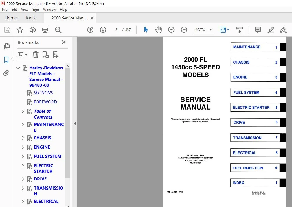
This manual is divided into nine sections, as identified оп the first page of this book. For quick and easy reference, all page numbers are peceded Ьу the section number. Therefore, if looking for the electrical section, simply ореп up the book to those pages preceded Ьу “8-“. lf referencing the engine section, flip to those pages begining with “3-,” and so оп.
PREPARATION FOR SERVICE :
Proper preparation is very important for efficient service work. А clean work area at the start of each job will allow you to perform the repair as easily and quickly as possiЫe, and reduce the incidence of misplaced tools and parts.
А motorcycle that is excessively dirty should Ье cleaned before work is begun. Cleaning will often uncover trouЫe spots or areas that need attention.
Gather tools, instruments and parts before work is started. lnterrupting а job to collect these items results in needless delay and distraction. Special tools made availaЫe for service work are listed in Section 1.
TABLE OF CONTENTS:
2000 Harley Davidson FLT Service Manual – PDF DOWNLOAD
Harley-Davidson FLT Models - Service Manual - 99483-00
............................................. 1
SECTIONS........................................................................................ 3
FOREWORD
....................................................................................... 5
Table of Contents............................................................................... 7
Suite... 1.................................................................................. 8
Suite... 2.................................................................................. 9
Suite... 3.................................................................................. 10
Suite... 4.................................................................................. 11
Suite... 5.................................................................................. 12
Suite... 6.................................................................................. 13
Suite... 7.................................................................................. 14
MAINTENANCE..................................................................................... 15
1. Service Intervals........................................................................ 16
2. Storage.................................................................................. 16
3. Fluid Requirements....................................................................... 18
4. Fastener Torque Values................................................................... 19
5. Metric Conversion Table.................................................................. 20
6. Troubleshooting.......................................................................... 21
7. Shop Practices........................................................................... 24
8. Tool Safety.............................................................................. 26
9. Tools.................................................................................... 28
10. Scheduled Maintenance Table............................................................. 43
11. Scheduled Maintenance Procedure......................................................... 48
CHASSIS......................................................................................... 64
1. Specifications........................................................................... 65
2. Vehicle Identification Number (VIN)...................................................... 67
3. Front Wheel.............................................................................. 68
4. Rear Wheel............................................................................... 73
5. Checking Cast Rim Runout................................................................. 78
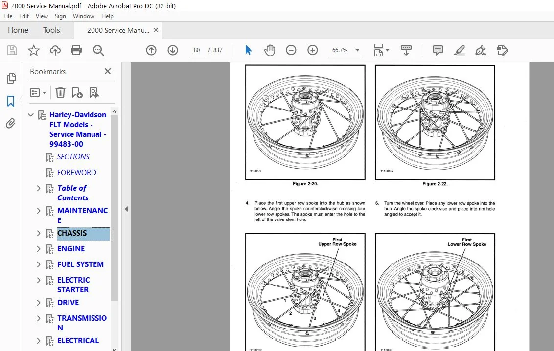
6. Wheel Lacing - 16 Inch Rim............................................................... 79
7. Truing Lacing Wheel...................................................................... 82
8. Tires and Tubes.......................................................................... 84
9. Vehicle Alignment........................................................................ 88
10. Front Brake Master Cylinder............................................................. 91
11. Rear Brake Master Cylinder.............................................................. 95
12. Front Brake Caliper.....................................................................103
13. Rear Brake Caliper......................................................................109
14. Bleeding Hydraulic Brake System.........................................................115
15. Front Forks.............................................................................116
16. Fork Stem and Bracket Assembly..........................................................120
17. Front/Rear Air Suspension...............................................................123
18. Rear Shcok Absorbers....................................................................128
19. Rear Swing Arm..........................................................................130
20. Throttle Cables (Non-Ultra)............................................................134
21. Clutch Cables...........................................................................139
22. Seat....................................................................................142
23. Saddlebags..............................................................................145
24. Tour-Pak................................................................................148
25. Tour-Pak Lights/Backrest/Fairing Cap (FLHT/C/U).........................................150
26. Lower Fairing/Glove Boxes (FLHTCU)......................................................153
27. Upper Fairing/Windshield/Fairing Cap (FLHT/C/U).........................................154
28. Upper Fairing/Windshield/Instruments Nacelle (FLHR/C)...................................161
29. Windshield/Headlamp Nacelle (FLHR/C)....................................................171
30. Front Fender............................................................................173
31. Rear Fender.............................................................................175
32. Jiffy Stand.............................................................................178
33. Exhaust System..........................................................................180
ENGINE..........................................................................................183
1. Specifications...........................................................................184
2. Serviced Wear Limits.....................................................................186
3. General Information......................................................................187
4. How to Use this Section..................................................................196
5. Stripping Motorcycle for Service.........................................................198
6. Assembling Motorcycle After Stripping....................................................199
7. Removing Engine From Chassis.............................................................202
8. Installing Engine in Chassis.............................................................207
9. Special Tools (for Servicing of the Twin Cam 88 Engine)..................................213
10. Top End Overhaul........................................................................217
Disassembly.............................................................................217
Assembly................................................................................221
11. Bottom End Overhaul.....................................................................229
Disassembly.............................................................................229
Assembly................................................................................231
12. Subassembly Service and Repair..........................................................237
Top End.................................................................................237
Breather Assembly.......................................................................237
Rocker Arm Assembly.....................................................................238
Push Rods/Lifters/Covers................................................................240
Cylinder Head...........................................................................243
Valve Guide Replacement.............................................................245
Valve and Seat Refacing.............................................................248
Cylinder....................................................................................253
Piston......................................................................................255
Upper Connecting Rod........................................................................258
Upper Connecting Rod Bushing............................................................258
Reaming Upper Rod Bushing...............................................................259
Honing Upper Rod Bushing................................................................260
Bottom End..................................................................................263
Cam Support Plate...........................................................................263
Crankshaft Bushing......................................................................263
Reaming Crankshaft Bushing..............................................................264
Camshafts/Camshaft Bearings.............................................................265
Cam Chain Tensioners....................................................................269
Oil Pressure Relief Valve...............................................................269
Cam Needle Bearings.....................................................................270
Oil Pump....................................................................................273
Crankcase...................................................................................275
Crankshaft (Roller) Bearing.............................................................275
Piston Jets.........................................................................276
Sprocket Shaft (Timken) Bearing.........................................................276
Cylinder Studs......................................................................282
Pipe Plug and Oil Fittings..........................................................282
Flywheel/Connectiong Rod Assembly...........................................................284
FUEL SYSTEM.....................................................................................285
1. Specifications...........................................................................286
2. Carburetor...............................................................................287
3. Air Cleaner (Carbureted Models)..........................................................298
4. Vacuum Operated Fule Valve (Carbureted Models)...........................................300
5. Fuel Tank................................................................................303
6. Evaporative Emissions Control System - California Models Only............................308
ELECTRIC STARTER................................................................................312
1. Specifications...........................................................................313
2. Starter System...........................................................................314
3. Starting System Diagnosis (FLow Chart)...................................................316
4. Diagnostics/Troubleshooting..............................................................318
Starting Activation Circuits............................................................319
5. Starter Relay............................................................................322
6. Starter..................................................................................324
7. Starter Solenoid.........................................................................332
8. Starter Jackshaft........................................................................333
DRIVE...........................................................................................335
1. Specifications...........................................................................336
2. Primary Chain and Sprockets..............................................................337
3. Clutch...................................................................................340
4. Secondary Drive Belt and Sprockets.......................................................345
5. Primary Chaincase........................................................................352
TRANSMISSION....................................................................................364
Transmission Power Flow Diagram.............................................................365
1. Specifications...........................................................................366
2. Shifter Linkage..........................................................................368
3. Shifter Cam Assembly/Shifter Forks.......................................................370
4. Clutch Release Cover.....................................................................375
5. Mainshaft/Countershaft...................................................................377
6. Main Drive Gear..........................................................................383
7. Transmission Case/Oil Pan................................................................388
ELECTRICAL......................................................................................394
1. Specifications...........................................................................395
2. Bulb Chart...............................................................................396
3. Ignition System (Carbureted).............................................................397
Checking for Trouble Codes..............................................................399
Diagnostic Check........................................................................404
4. Ignition Module..........................................................................434
5. Engine Sensors...........................................................................434
6. Spark Plugs/Spark Plug Cables............................................................436
7. Ignition Coil............................................................................437
8. Charging System..........................................................................439
9. Alternator/Stator........................................................................444
10. Voltage Regulator.......................................................................448
11. Battery.................................................................................451
12. Headlamp (FLHR/C, FLHT/C/U).............................................................456
13. Headlamp (FLTR).........................................................................459
14. Passing Lamps...........................................................................462
15. Tail Lamp Asssembly.....................................................................465
16. Fender Tip Lamps........................................................................467
17. Turn Signal Lamps.......................................................................472
18. Turn Signal Module......................................................................476
19. Ignition/Light Key Switch and Fork Lock.................................................482
20. Fairing Cap Switches (FLHTC/U)..........................................................486
21. Instrument Nacelle Switches (FLTR)......................................................489
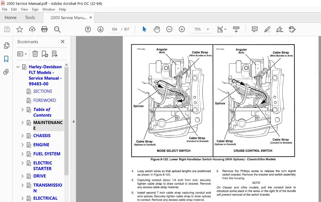
22. Handlebar Switches......................................................................494
23. Stoplight Switches......................................................................510
24. Neutral Switch..........................................................................511
25. Horn....................................................................................512
26. Cigarette Lighter (FLHTCU, FLTR)........................................................513
27. Gauges/Instruments......................................................................514
28. Electronic Speedometer Diagnostics......................................................523
29. Electronic Speedometer Performance Check................................................528
30. Fuel Level Sender (Carbureted)..........................................................531
31. Cruise Control (FLHTC/U,FLTR)...........................................................534
Premium Sound System (FLHTC/U, FLTR)....................................................557
32. Wiring Harnesses and Cables (FLHT/C/U)..................................................604
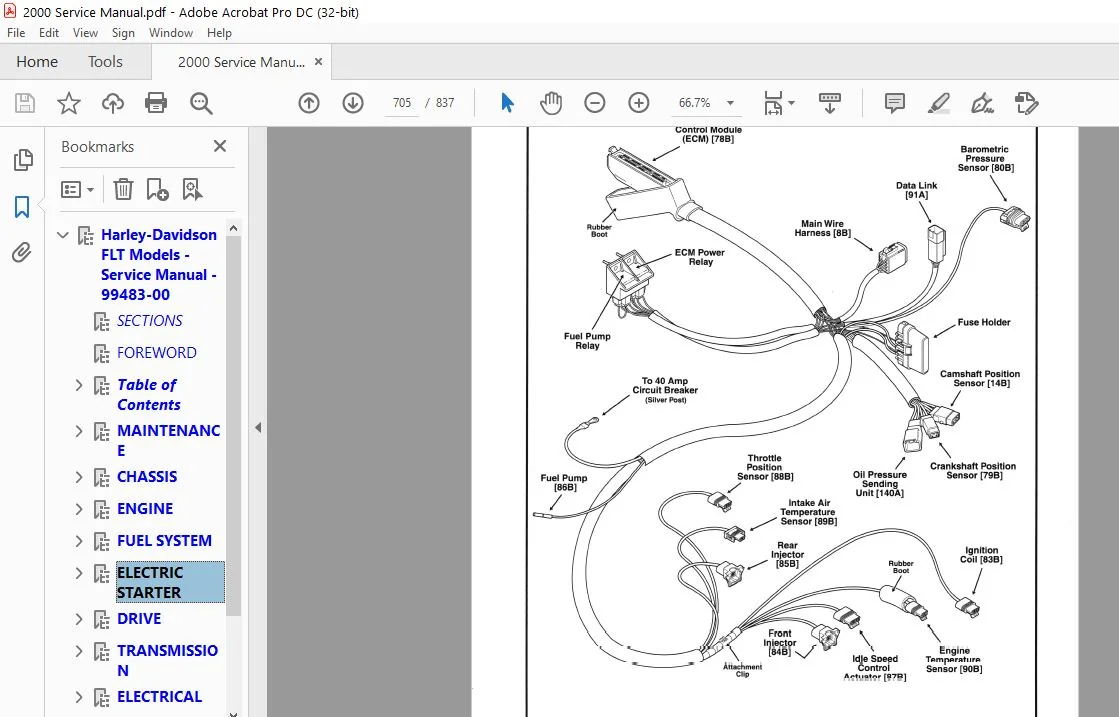
FUEL INJECTION..................................................................................621
SECTION 9A : INTRODUCTION...................................................................623
Sequential Port Fuel Injection System...................................................625
General Information.....................................................................625
Component Descriptions..................................................................625
EFI Component Schematic.................................................................626
EFI Pictorial Schematic.................................................................627
SECTION 9B : SYSTEM DIAGNOSTICS.............................................................631
Introdcution............................................................................632
9B-1 Checking for Trouble Codes.........................................................633
9B-2 Retrieving Troubles Codes..........................................................635
9B-3 Tools..............................................................................639
9B-4 Diagnosing System Problems.........................................................642
Diagnostic Check........................................................................646
Chart A-1, No Check Engine Lamp at Key ON...............................................648
Chart A-2, Check Engine Lamp ON Continuously............................................650
Chart A-3, Engine Cranks but will Not Start.............................................652
Chart A-4, No ECM Power.................................................................656
Chart B-1, Fuel System Electrical Test..................................................659
Chart B-2, Fuel Pressure Test...........................................................664
Chart C-1, Idle Speed Control...........................................................668
Chart C-2, Misfire at Idle or Under Load................................................670
Trouble Code 11, Throttle Position Sensor...............................................672
Trouble Code 12, barometric Pressure Sensor.............................................674
Trouble Code 14, Engine Temerature Sensor...............................................676
Trouble Code 15, Intake Air Temperature Sensor..........................................678
Trouble Code 16, Battery Voltage........................................................680
Trouble Codes 23 and 32, Fuel Injector..................................................682
Trouble Code 24 and 25, Ignition Coil...................................................685
Trouble Code 33, Fuel Pump Relay........................................................688
Trouble Code 35, Tachometer - Except FLHR/C-I...........................................690
Trouble Code 41, Crankshaft Position Sensor.............................................692
Trouble Code 42, Camshaft Position Sensor...............................................694
Trouble Code 44, Bank Angle Sensor......................................................696
Trouble Codes 52, 53, 54 and 55, ECM Failure............................................697
Trouble Code 56, Crank Position Sensor and Cam Position Sensor Timing...................697
SECTION 9C : REMOVAL/REPLACEMENT............................................................699
9C-1 Electrical Bracket Assembly........................................................701
Side Cover..........................................................................701
Data Link Connector.................................................................702
Electrical Relays...................................................................702
Fuses...............................................................................702
Electronic Control Module (ECM).....................................................703
Barometric Pressure Sensor..........................................................703
EFI Wire Harness....................................................................704
EFI Wire Harness Connector Terminal Repair..........................................707
9C-2 Sensors............................................................................708
Barometric Pressure Sensor..........................................................708
Throttle Position Sensor............................................................708
Intake Air Temperature Sensor.......................................................708
Camshaft Position Sensor............................................................708
Crankshaft Position Sensor..........................................................710
Engine Temperature Sensor...........................................................711
Bank Angle Sensor...................................................................711
9C-3 Fuel Tank Assembly.................................................................713
Fuel tank, Complete Removal.........................................................713
FLHTC/U-I, FLTR-I...............................................................713
FLHR/C-I........................................................................715
Fuel Tank, Partial Removal..........................................................717
FLHTC/U-I, FLTR-I...............................................................717
FLHR/C-I........................................................................718
Console Pod/Canopy, FLHTC/U-I, FLTR-I...............................................720
Instrument Console/Canopy, FLHR/C-I.................................................721
Fuel Filter Canister................................................................724
Fuel Pump...........................................................................724
Fuel Pump Wiring....................................................................725
Fuel Level Sender...................................................................726
Canopy Connector/O-Ring Seal........................................................726
Fuel Supply/Return Check Valves.....................................................727
9C-4 Air Cleaner Assembly...............................................................729
Air Cleaner.........................................................................729
Warm-Slow Idle Speed Adjustment.....................................................730
Cold Idle Speed Adjustment..........................................................730
Charcoal Canister (California Models Only)..........................................731
9C-5 Induction Module Assembly..........................................................733
Induction Module....................................................................733
Fuel Supply/Return Lines............................................................735
Fuel Injectors......................................................................736
Fuel Pressure Regulator.............................................................737
Intake Air Temperature Sensor.......................................................738
Throttle Position sensor............................................................738
Idle Speed Control Actuator.........................................................740
Idle Speed Control Actuator - Adjustment............................................741
Cam Lever Assembly..................................................................741
9C-6 Ignition System....................................................................744
Igniton Coil........................................................................744
ELECTRICAL CONNECTOR............................................................................745
A. Electrical Connector Service and Repair..................................................745
Deutsch Electrical Connectors...........................................................747
AMP Multilock Electrical Connectors.....................................................753
Packard Electrical Connectors...........................................................758
Sealed Butt Splice Connectors...........................................................763
Amp Electrical Connectors...............................................................764
B. Electrical Connector Locations...........................................................767
FLHT, FLHTC, FLHTC-I, FLHTCU-I..........................................................769
FLHR, FLHRC-I...........................................................................775
FLTR, FLTR-I............................................................................777
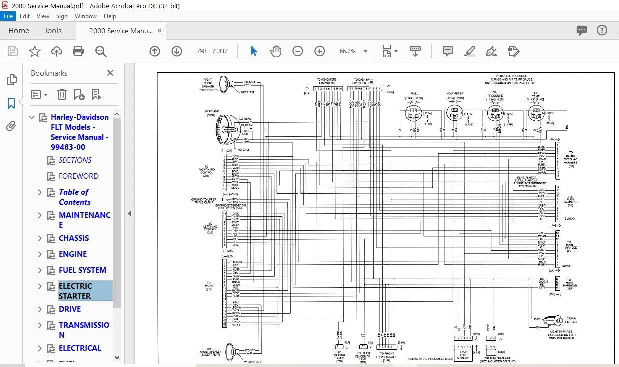
C. 2000 Wiring Diagrams.....................................................................781
Main Harness............................................................................783
Interconnect Harness....................................................................787
Ignition Harness, Engine Sensor Harness and Engine MAnagement Circuitry.................791
Ignition Switch, Tail Lamps, Fender Tip Lamps and Tour-Pak Lights.......................795
Starting and Charging...................................................................799
Handlebar Controls, Speedometer, Tachometer, Indicator Lamps and Dash Panel Switches....803
Radio, CB/Intercom, Rear Speakers and Cruise............................................807
Main Harness............................................................................811
Ignition Harness, Engine Sensor Harness and Engine Management Circuitry.................815
Starting and Charging...................................................................819
Handlebar Controls, Indocator Lamps, Tail Lamp, Passing Lamps and Directional Lamps.....823
Chassis and Audio Harness...............................................................827
INDEX...........................................................................................831
A to E......................................................................................832
F to M......................................................................................833
N to T......................................................................................834
T to W......................................................................................835
2000 HARLEY DAVIDSON FLT SERVICE MANUAL – PDF DOWNLOAD:
PLEASE NOTE:
This is the same manual used by the dealers to diagnose and troubleshoot your vehicle
You will be directed to the download page as soon as the purchase is completed. The whole payment and downloading process will take anywhere between 2-5 minutes
Need any other service / repair / parts manual, please feel free to contact [email protected] . We still have 50,000 manuals unlisted
S.V
✹
What Our Customers Say
★★★★★Live reviews from customers
Loading customer reviews...
🌟 Related Products
Discover more professional manuals for your equipment