Trusted Business
Verified & Licensed
Virus Free Files
100% Safe Downloads
Secure Payment
SSL Protected
Instant Delivery
Available Immediately
2000 NISSAN ALTIMA L30 Series Service Manual PDF DOWNLOAD
$35.95
2000 NISSAN ALTIMA L30 Series Service Manual PDF DOWNLOAD
Instant PDF Download
Available immediately
Save to Your Device
Download & keep forever
Antivirus Scanned
100% virus-free
Trusted Worldwide
175,000+ customers
Description
2000 NISSAN ALTIMA L30 Series Service Manual PDF DOWNLOAD
FILE DETAILS:
2000 NISSAN ALTIMA L30 Series Service Manual PDF DOWNLOAD
Language : English
Pages : 1690
Downloadable :Yes
File Type : PDF
IMAGES PREVIEW OF THE MANUAL:
Contact us: [email protected]
https://vimeo.com/850048173?share=copy
DESCRIPTION:
2000 NISSAN ALTIMA L30 Series Service Manual PDF DOWNLOAD
FOREWORD
- This manual contains maintenance and repair procedures for the 2000 Nissan ALTIMA.
- In order to assure your safety and the efficient functioning of the vehicle, this manual should be read thoroughly.
- It is especially important that the PRECAUTIONS in the GI section be completely understood before starting any repair task. All information in this manual is based on the latest product information at the time of publication.
- The right is reserved to make changes in specifications and methods at any time without notice.
PRECAUTIONS:
- Before proceeding with disassembly, thoroughly clean the outside of the transaxle. It is important to prevent the internal parts from becoming contaminated by dirt or other foreign matter
- Disassembly should be done in a clean work area.
- Use lint-free cloth or towels for wiping parts clean. Common shop rags can leave fibers that could interfere with the operation of the transaxle.
- Place disassembled parts in order for easier and proper assembly.
- All parts should be carefully cleaned with a general purpose, non-flammable solvent before inspection or reassembly. Gaskets, seals and O-rings should be replaced any time the transaxle is disassembled.
- It is very important to perform functional tests whenever they are indicated.
- The valve body contains precision parts and requires extreme care when parts are removed and serviced. Place disassembled valve body parts in order for easier and proper assembly. Care will also prevent springs and small parts from becoming scattered or lost.
- Properly installed valves, sleeves, plugs, etc. will slide along bores in valve body under their own weight.
- Before assembly, apply a coat of recommended ATF to all parts. Apply petroleum jelly to protect O-rings and seals, or hold bearings and washers in place during assembly. Do not use grease.
- Extreme care should be taken to avoid damage to O-rings, seals and gaskets when assembling.
- Replace ATF cooler if excessive foreign material is found in oil pan or clogging strainer. Refer to ‘‘ATF COOLER SERVICE’’ (Refer to AT-8).
- After overhaul, refill the transaxle with new ATF.
- When the A/T drain plug is removed, only some of the fluid is drained. Old A/T fluid will remain in torque converter and ATF cooling system. Always follow the procedures under ‘‘Changing A/T Fluid’’ in the MA section when changing A/T fluid. Service Notice or Precautions FAIL-SAFE The TCM
TABLE OF CONTENTS:
2000 NISSAN ALTIMA L30 Series Service Manual PDF DOWNLOAD
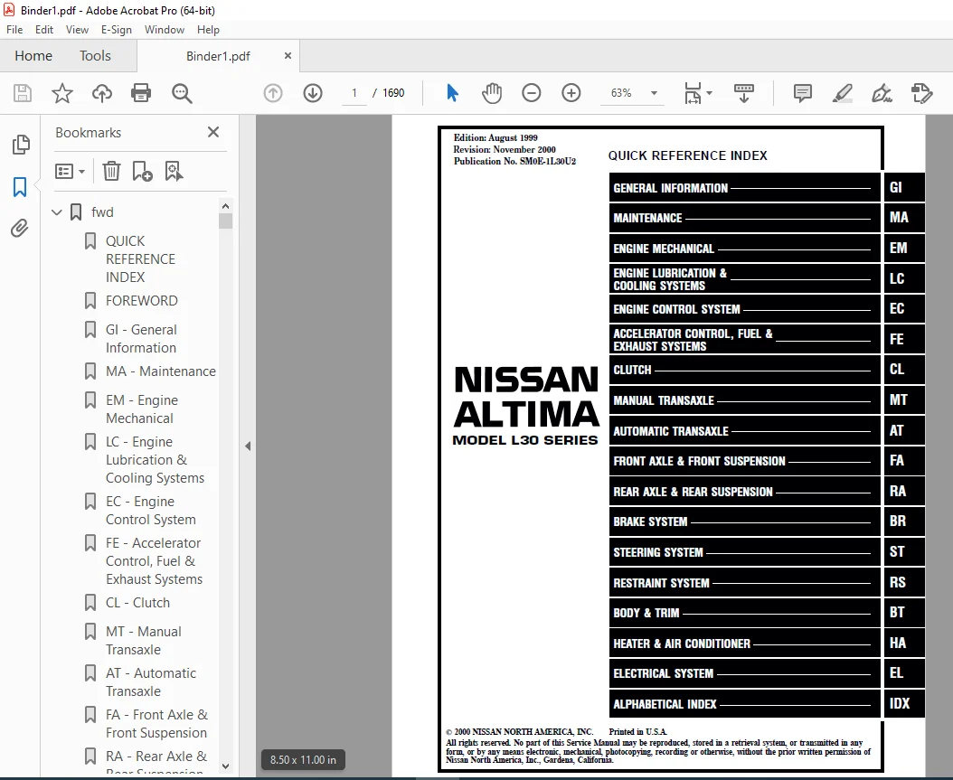
fwd 1
QUICK REFERENCE INDEX 1
FOREWORD 2
GI – General Information 0
MA – Maintenance 0
EM – Engine Mechanical 0
LC – Engine Lubrication & Cooling Systems 0
EC – Engine Control System 0
FE – Accelerator Control, Fuel & Exhaust Systems 0
CL – Clutch 0
MT – Manual Transaxle 0
AT – Automatic Transaxle 0
FA – Front Axle & Front Suspension 0
RA – Rear Axle & Rear Suspension 0
BR – Brake System 0
ST – Steering System 0
RS – Restraint System 0
BT – Body & Trim 0
HA – Heater & Air Conditioner 0
EL – Electrical System 0
IDX – Alphabetical Index 1
SUPER MULTIPLE JUNCTION (SMJ) 0
FUSE BLOCK — Junction Box (J/B) 2
FUSE AND FUSIBLE LINK BOX 3
ELECTRICAL UNITS 4
JOINT CONNECTOR (J/C) 5
QUICK REFERENCE CHART 6
COMMENT SHEET 3
GST Mode 6 – Test Value & Test Limit Chart 5
at 6
QUICK REFERENCE INDEX 0
Table of Contents 6
DIAGNOSTIC TROUBLE CODE INDEX 9
Alphabetical & P No Index for DTC 9
PRECAUTIONS 10
Supplemental Restraint System (SRS) ‘‘AIR BAG’’ and ‘‘SEAT BELT PRE-TENSIONER’’ 10
Precautions for On Board Diagnostic (OBD) System of A/T and Engine 10
Precautions 11
Service Notice or Precautions 12
Special Service Tools 14
Commercial Service Tools 17
OVERALL SYSTEM 18
A/T Electrical Parts Location 18
Circuit Diagram for Quick Pinpoint Check 19
Cross-sectional View 20
Hydraulic Control Circuit 21
Shift Mechanism 22
Control System 31
Control Mechanism 33
Control Valve 38
ON BOARD DIAGNOSTIC SYSTEM DESCRIPTION 39
Introduction 39
OBD-II Function for A/T System 39
One or Two Trip Detection Logic of OBD-II 39
OBD-II Diagnostic Trouble Code (DTC) 39
Malfunction Indicator Lamp (MIL) 43
CONSULT-II 43
Diagnostic Procedure Without CONSULT-II 50
TROUBLE DIAGNOSIS — Introduction 54
Introduction 54
Diagnostic Worksheet 55
Work Flow 58
TROUBLE DIAGNOSIS — Basic Inspection 59
A/T Fluid Check 59
Stall Test 59
Line Pressure Test 62
Road Test 63
TROUBLE DIAGNOSIS — General Description 74
Symptom Chart 74
TCM Terminals and Reference Value 77
TROUBLE DIAGNOSIS FOR POWER SUPPLY 81
Main Power Supply and Ground Circuit 81
TROUBLE DIAGNOSIS FOR DTC P0705 83
Park/Neutral Position (PNP) Switch 83
TROUBLE DIAGNOSIS FOR DTC P0710 88
A/T Fluid Temperature Sensor 88
TROUBLE DIAGNOSIS FOR DTC P0720 93
Vehicle Speed SensorzA/T (Revolution sensor) 93
TROUBLE DIAGNOSIS FOR DTC P0725 97
Engine Speed Signal 97
TROUBLE DIAGNOSIS FOR DTC P0731 101
A/T 1st Gear Function 101
TROUBLE DIAGNOSIS FOR DTC P0732 107
A/T 2nd Gear Function 107
TROUBLE DIAGNOSIS FOR DTC P0733 113
A/T 3rd Gear Function 113
TROUBLE DIAGNOSIS FOR DTC P0734 119
A/T 4th Gear Function 119
TROUBLE DIAGNOSIS FOR DTC P0740 126
Torque Converter Clutch Solenoid Valve 126
TROUBLE DIAGNOSIS FOR DTC P0744 131
A/T TCC S/V Function (Lock-up) 131
TROUBLE DIAGNOSIS FOR DTC P0745 139
Line Pressure Solenoid Valve 139
TROUBLE DIAGNOSIS FOR DTC P0750 144
Shift Solenoid Valve A 144
TROUBLE DIAGNOSIS FOR DTC P0755 149
Shift Solenoid Valve B 149
TROUBLE DIAGNOSIS FOR DTC P1705 154
Throttle Position Sensor 154
TROUBLE DIAGNOSIS FOR DTC P1760 161
Overrun Clutch Solenoid Valve 161
TROUBLE DIAGNOSIS FOR BATT/FLUID TEMP SEN 166
A/T Fluid Temperature Sensor Circuit and TCM Power Source 166
TROUBLE DIAGNOSIS FOR VHCL SPEED SENzMTR 171
Vehicle Speed SensorzMTR 171
TROUBLE DIAGNOSIS FOR CONTROL UNIT (RAM), CONTROL UNIT (ROM) 175
TCM (Transmission Control Module) 175
TROUBLE DIAGNOSIS FOR CONTROL UNIT (EEPROM) 177
TCM (Transmission Control Module) 177
TROUBLE DIAGNOSES FOR SYMPTOMS 179
Non-detectable Items 179
1 O/D OFF Indicator Lamp Does Not Come On 182
2 Engine Cannot Be Started In ‘‘P’’ and ‘‘N’’ Position 183
3 In ‘‘P’’ Position, Vehicle Moves Forward or Backward When Pushed 183
4 In ‘‘N’’ Position, Vehicle Moves 184
5 Large Shock ‘‘N’’ ® ‘‘R’’ Position 185
6 Vehicle Does Not Creep Backward In ‘‘R’’ Position 186
7 Vehicle Does Not Creep Forward In ‘‘D’’, ‘‘2’’ or ‘‘1’’ Position 187
8 Vehicle Cannot Be Started From D1 188
9 A/T Does Not Shift: D1 ® D2 or Does Not Kickdown: D4 ® D2 189
10 A/T Does Not Shift: D2 ® D3 190
11 A/T Does Not Shift: D3 ® D4 191
12 A/T Does Not Perform Lock-up 192
13 A/T Does Not Hold Lock-up Condition 193
14 Lock-up Is Not Released 193
15 Engine Speed Does Not Return To Idle (Light Braking D4 ® D3) 194
16 Vehicle Does Not Start From D1 195
17 A/T Does Not Shift: D4 ® D3, When Overdrive Control Switch ‘‘ON’’ ® ‘‘OFF’’ 195
18 A/T Does Not Shift: D3 ® 22, When Selector Lever ‘‘D’’ ® ‘‘2’’ Position 196
19 A/T Does Not Shift: 22 ® 11, When Selector Lever ‘‘2’’ ® ‘‘1’’ Position 196
20 Vehicle Does Not Decelerate By Engine Brake 197
21 TCM Self-diagnosis Does Not Activate (Park/Neutral Position (PNP), Overdrive Control and Throttle Position Switch Circuit Checks) 197
TROUBLE DIAGNOSES — A/T Shift Lock System 205
Description 205
Shift Lock System Electrical Parts Location 205
Wiring Diagram — SHIFT — 206
Diagnostic Procedure 207
Key Interlock Cable 209
Component Check 210
ON-VEHICLE SERVICE 212
Control Valve Assembly and Accumulator 212
Revolution Sensor Replacement 213
Park/Neutral Position (PNP) Switch Adjustment 213
Control Cable Adjustment 214
Differential Side Oil Seal Replacement 214
REMOVAL AND INSTALLATION 215
Removal 215
Installation 216
MAJOR OVERHAUL 218
Locations of Adjusting Shims, Needle Bearings, Thrust Washers and Snap Rings 221
Oil Channel 222
DISASSEMBLY 223
REPAIR FOR COMPONENT PARTS 237
Manual Shaft 237
Oil Pump 239
Control Valve Assembly 243
Control Valve Upper Body 251
Control Valve Lower Body 255
Reverse Clutch 257
High Clutch 260
Forward Clutch and Overrun Clutch 264
Low & Reverse Brake 270
Rear Internal Gear, Forward Clutch Hub and Overrun Clutch Hub 272
Output Shaft, Idler Gear, Reduction Pinion Gear and Bearing Retainer 276
Band Servo Piston Assembly 281
Final Drive 286
ASSEMBLY 290
Assembly 1 290
Adjustment 1 290
Assembly 2 295
Adjustment 2 301
Assembly 3 303
SERVICE DATA AND SPECIFICATIONS (SDS) 309
General Specifications 309
Specifications and Adjustments 309
Shift Solenoid Valves 315
Resistance 315
ATF Temp sensor 315
Revolution sensor 315
Dropping resistor 316
SUPER MULTIPLE JUNCTION (SMJ) 0
FUSE BLOCK — Junction Box (J/B) 2
FUSE AND FUSIBLE LINK BOX 3
ELECTRICAL UNITS 4
JOINT CONNECTOR (J/C) 5
br 318
QUICK REFERENCE INDEX 0
Table of Contents 318
PRECAUTIONS AND PREPARATION 320
Supplemental Restraint System (SRS) ‘‘AIR BAG’’ and ‘‘SEAT BELT PRE-TENSIONER’’ 320
Precautions for Brake System 320
Commercial Service Tools 321
NOISE, VIBRATION AND HARSHNESS (NVH) TROUBLESHOOTING 322
NVH Troubleshooting Chart 322
ON-VEHICLE SERVICE 323
Checking Brake Fluid Level 323
Checking Brake Line 323
Changing Brake Fluid 323
Brake Burnishing Procedure 323
Bleeding Brake System 324
BRAKE HYDRAULIC LINE 325
CONTROL VALVE 326
Proportioning Valve 326
BRAKE PEDAL AND BRACKET 328
Removal and Installation 328
Inspection 328
Adjustment 328
MASTER CYLINDER 330
Removal 330
Disassembly 330
Inspection 331
Assembly 331
Installation 332
BRAKE BOOSTER 333
On-vehicle Service 333
Removal 333
Inspection 334
Installation 334
VACUUM HOSE 335
Removal and Installation 335
Inspection 335
FRONT DISC BRAKE 336
Pad Replacement 336
Removal 337
Disassembly 338
Inspection — Caliper 338
Inspection — Rotor 339
Assembly 339
Installation 339
REAR DRUM BRAKE 340
Removal 340
Inspection — Wheel Cylinder 342
Wheel Cylinder Overhaul 342
Inspection — Drum 342
Inspection — Lining 342
Installation 343
REAR DISC BRAKE 345
Pad Replacement 345
Removal 348
Disassembly 348
Inspection — Caliper 349
Inspection — Rotor 350
Assembly 350
Installation 353
PARKING BRAKE CONTROL 354
Removal and Installation 354
Inspection 354
Adjustment 355
ANTI-LOCK BRAKE SYSTEM 356
Purpose 356
Operation 356
ABS Hydraulic Circuit 356
System Components 357
System Description 357
Removal and Installation 358
FRONT WHEEL SENSOR 358
REAR WHEEL SENSOR 358
CONTROL UNIT 359
ACTUATOR 359
ACTUATOR RELAY ASSEMBLY 359
TROUBLE DIAGNOSES 360
How to Perform Trouble Diagnoses for Quick and Accurate Repair 360
Preliminary Check 361
Component Parts and Harness Connector Location 362
Schematic 363
Wiring Diagram •ABS• 364
ABS Control Unit Terminal Reference Chart 369
Self-diagnosis 370
FUNCTION 370
SELF-DIAGNOSIS PROCEDURE 370
HOW TO READ SELF-DIAGNOSTIC RESULTS (Malfunction codes) 371
HOW TO ERASE SELF-DIAGNOSTIC RESULTS (Malfunction codes) 371
MALFUNCTION CODE/SYMPTOM CHART 372
CONSULT-II 373
CONSULT-II APPLICATION TO ABS 373
CONSULT-II Inspection Procedure 374
SELF-DIAGNOSIS PROCEDURE 374
SELF-DIAGNOSTIC RESULTS MODE 375
DATA MONITOR PROCEDURE 376
ACTIVE TEST PROCEDURE 377
DATA MONITOR MODE 378
ACTIVE TEST MODE 378
Ground Circuit Check 379
ACTUATOR MOTOR GROUND 379
CONTROL UNIT GROUND 379
ABS RELAY UNIT GROUND 379
TROUBLE DIAGNOSES FOR SELF-DIAGNOSTIC ITEMS 380
Diagnostic Procedure 1 (ABS actuator solenoid valve) 380
Diagnostic Procedure 2 (Wheel sensor or rotor) 382
COMPONENT INSPECTION 383
Diagnostic Procedure 3 (Motor relay or motor) 384
Diagnostic Procedure 4 (Solenoid valve relay) 387
Diagnostic Procedure 5 (Low voltage) 390
Diagnostic Procedure 6 (Control unit) 391
TROUBLE DIAGNOSIS FOR SYMPTOMS 392
Diagnostic Procedure 7 (ABS works frequently) 392
Diagnostic Procedure 8 (Unexpected pedal action) 393
Diagnostic Procedure 9 (Long stopping distance) 393
Diagnostic Procedure 10 (ABS does not work) 394
Diagnostic Procedure 11 (Pedal vibration and noise) 394
Diagnostic Procedure 12 (Warning lamp does not come on when ignition switch is turned ON) 395
Diagnostic Procedure 13 (Warning lamp stays on when ignition switch is turned ON) 397
SERVICE DATA AND SPECIFICATIONS (SDS) 400
General Specifications 400
Inspection and Adjustment 400
SUPER MULTIPLE JUNCTION (SMJ) 0
FUSE BLOCK — Junction Box (J/B) 2
FUSE AND FUSIBLE LINK BOX 3
ELECTRICAL UNITS 4
JOINT CONNECTOR (J/C) 5
bt 402
QUICK REFERENCE INDEX 0
Table of Contents 402
PRECAUTIONS AND PREPARATION 403
Service Notice 403
Supplemental Restraint System (SRS) ‘‘AIR BAG’’ and ‘‘SEAT BELT PRE-TENSIONER’’ 403
Clip and Fastener 404
BODY END 408
Body Front End 408
Body Rear End and Opener 412
DOOR 416
Front Door 416
Rear Door 418
INSTRUMENT PANEL 419
INTERIOR TRIM 422
Side and Floor Trim 422
Door Trim 424
Roof Trim 426
Luggage Room Trim 427
EXTERIOR 428
Front hood insulator 429
Cowl top grille and cowl top seal 429
Front windshield molding 429
Windshield upper and side molding 429
Sunroof lid weatherstrip 430
Body side drip weatherstrip 430
Body side welt 430
Door sash molding 430
Door outside molding 431
Door parting seal 431
Side guard molding 431
Door weatherstrip 432
Mudguards 432
Rear combination lamp 433
Front tower bar 433
Trunk lid weatherstrip 433
Rear air spoiler 434
Rear window molding 434
SEAT 435
Front Seat 436
Rear Seat 438
SUNROOF 440
Trouble Diagnoses 444
WINDSHIELD AND WINDOWS 448
Windshield and Rear Window 449
Quarter Window 450
MIRROR 451
Door Mirror 451
Rearview Mirror 452
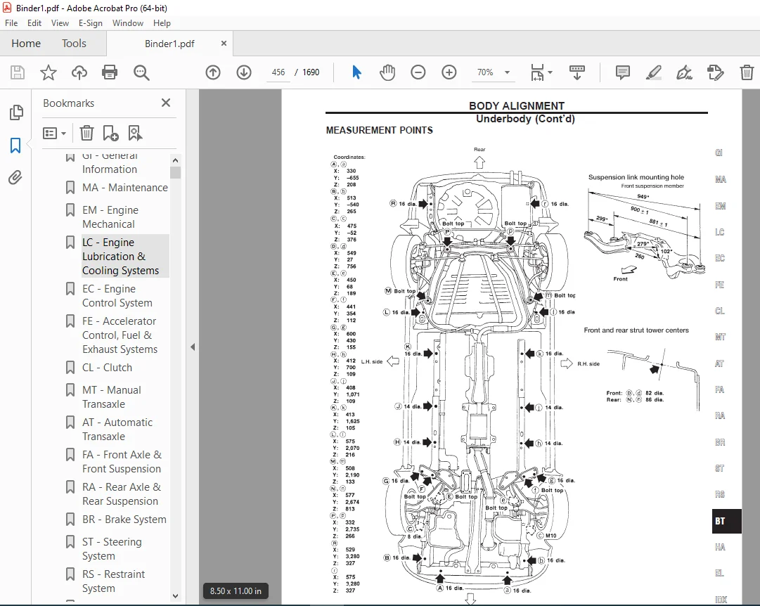
BODY ALIGNMENT 453
Engine Compartment 453
Underbody 455
cl 458
QUICK REFERENCE INDEX 0
Table of Contents 458
PRECAUTIONS AND PREPARATION 459
Precautions 459
Special Service Tools 459
Commercial Service Tools 459
NOISE, VIBRATION AND HARSHNESS (NVH) TROUBLESHOOTING 460
NVH Troubleshooting Chart 460
CLUTCH SYSTEM — Hydraulic Type 461
INSPECTION AND ADJUSTMENT 462
Adjusting Clutch Pedal 462
Bleeding Procedure 463
HYDRAULIC CLUTCH CONTROL 464
Clutch Master Cylinder 464
Operating Cylinder 465
CLUTCH RELEASE MECHANISM 466
CLUTCH DISC AND CLUTCH COVER 468
Clutch Disc 468
Clutch Cover and Flywheel 469
SERVICE DATA AND SPECIFICATIONS (SDS) 470
General Specifications 470
Inspection and Adjustment 470
ec 472
QUICK REFERENCE INDEX 0
Table of Contents 472
DIAGNOSTIC TROUBLE CODE INDEX 475
Alphabetical & P No Index for DTC 475
PRECAUTIONS AND PREPARATION 477
Special Service Tools 477
Commercial Service Tools 477
Supplemental Restraint System (SRS) “AIR BAG” and “SEAT BELT PRE-TENSIONER” 479
Precautions for On Board Diagnostic (OBD) System of Engine and A/T 479
Engine Fuel & Emission Control System 480
Precautions 481
ENGINE AND EMISSION CONTROL OVERALL SYSTEM 483
Circuit Diagram 483
Engine Control Component Parts Location 484
System Diagram 486
Vacuum Hose Drawing 487
System Chart 488
ENGINE AND EMISSION BASIC CONTROL SYSTEM DESCRIPTION 489
Multiport Fuel Injection (MFI) System 489
Distributor Ignition (DI) System 491
Air Conditioning Cut Control 492
Fuel Cut Control 493
EVAPORATIVE EMISSION SYSTEM 494
Description 494
Inspection 494
Evaporative Emission Line Drawing 497
On Board Refueling Vapor Recovery (ORVR) 499
POSITIVE CRANKCASE VENTILATION 504
Description 504
Inspection 504
BASIC SERVICE PROCEDURE 505
Fuel Pressure Release 505
Fuel Pressure Check 505
Fuel Pressure Regulator Check 506
Injector Removal and Installation 506
Fast Idle Cam (FIC) 506
Idle Speed/Ignition Timing/Idle Mixture Ratio Adjustment 508
ON BOARD DIAGNOSTIC SYSTEM DESCRIPTION 514
Introduction 514
Two Trip Detection Logic 514
Emission-related Diagnostic Information 515
Malfunction Indicator Lamp (MIL) 529
OBD System Operation Chart 533
CONSULT-II 538
Generic Scan Tool (GST) 549
TROUBLE DIAGNOSIS — Introduction 551
Introduction 551
Diagnostic Worksheet 551
TROUBLE DIAGNOSIS — Work Flow 553
Work Flow 553
Description for Work Flow 554
TROUBLE DIAGNOSIS — Basic Inspection 555
Basic Inspection 555
TROUBLE DIAGNOSIS — General Description 561
Diagnostic Trouble Code (DTC) Inspection Priority Chart 561
Fail-Safe Chart 562
Symptom Matrix Chart 563
CONSULT-II Reference Value in Data Monitor Mode 566
Major Sensor Reference Graph in Data Monitor Mode 568
ECM Terminals and Reference Value 570
TROUBLE DIAGNOSIS FOR INTERMITTENT INCIDENT 580
Description 580
Common I/I Report Situations 580
Diagnostic Procedure 580
TROUBLE DIAGNOSIS FOR POWER SUPPLY 581
Main Power Supply and Ground Circuit 581
TROUBLE DIAGNOSIS FOR DTC P0100 586
Mass Air Flow Sensor (MAFS) 586
TROUBLE DIAGNOSIS FOR DTC P0105 (WITH EXTERNAL ABSOLUTE PRESSURE SENSOR) 595
Absolute Pressure Sensor 595
TROUBLE DIAGNOSIS FOR DTC P0105 (WITHOUT EXTERNAL ABSOLUTE PRESSURE SENSOR) 600
Absolute Pressure Sensor 600
TROUBLE DIAGNOSIS FOR DTC P0110 601
Intake Air Temperature Sensor 601
TROUBLE DIAGNOSIS FOR DTC P0115 607
Engine Coolant Temperature Sensor (ECTS) 607
TROUBLE DIAGNOSIS FOR DTC P0120 612
Throttle Position Sensor 612
TROUBLE DIAGNOSIS FOR DTC P0125 625
Engine Coolant Temperature (ECT) Sensor 625
TROUBLE DIAGNOSIS FOR DTC P0130 630
Front Heated Oxygen Sensor (Circuit) (Front HO2S) 630
TROUBLE DIAGNOSIS FOR DTC P0131 637
Front Heated Oxygen Sensor (Lean Shift Monitoring) (Front HO2S) 637
TROUBLE DIAGNOSIS FOR DTC P0132 645
Front Heated Oxygen Sensor (Rich Shift Monitoring) (Front HO2S) 645
TROUBLE DIAGNOSIS FOR DTC P0133 653
Front Heated Oxygen Sensor (Response Monitoring) (Front HO2S) 653
TROUBLE DIAGNOSIS FOR DTC P0134 661
Front Heated Oxygen Sensor (High Voltage) (Front HO2S) 661
TROUBLE DIAGNOSIS FOR DTC P0135 668
Front Heated Oxygen Sensor Heater 668
TROUBLE DIAGNOSIS FOR DTC P0137 672
Rear Heated Oxygen Sensor (Min Voltage Monitoring) (Rear HO2S) 672
TROUBLE DIAGNOSIS FOR DTC P0138 680
Rear Heated Oxygen Sensor (Max Voltage Monitoring) (Rear HO2S) 680
TROUBLE DIAGNOSIS FOR DTC P0139 687
Rear Heated Oxygen Sensor (Response Monitoring) (Rear HO2S) 687
TROUBLE DIAGNOSIS FOR DTC P0140 693
Rear Heated Oxygen Sensor (High Voltage) (Rear HO2S) 693
TROUBLE DIAGNOSIS FOR DTC P0141 699
Rear Heated Oxygen Sensor Heater 699
TROUBLE DIAGNOSIS FOR DTC P0171 703
Fuel Injection System Function (Lean side) 703
TROUBLE DIAGNOSIS FOR DTC P0172 708
Fuel Injection System Function (Rich side) 708
TROUBLE DIAGNOSIS FOR DTC P0180 713
Fuel Tank Temperature Sensor 713
TROUBLE DIAGNOSIS FOR DTC P0300 – P0304 717
No4 -1Cylinder Misfire, Multiple Cylinder Misfire 717
TROUBLE DIAGNOSIS FOR DTC P0325 722
Knock Sensor (KS) 722
TROUBLE DIAGNOSIS FOR DTC P0335 727
Crankshaft Position Sensor (CKPS) (OBD) 727
TROUBLE DIAGNOSIS FOR DTC P0340 732
Camshaft Position Sensor (CMPS) 732
TROUBLE DIAGNOSIS FOR DTC P0400 739
EGR Function (Close) 739
TROUBLE DIAGNOSIS FOR DTC P0402 748
EGRC-BPT Valve Function 748
TROUBLE DIAGNOSIS FOR DTC P0420 753
Three Way Catalyst Function 753
TROUBLE DIAGNOSIS FOR DTC P0440 757
Evaporative Emission (EVAP) Control System (Small Leak) (Negative Pressure) 757
TROUBLE DIAGNOSIS FOR DTC P0443 766
Evaporative Emission (EVAP) Canister Purge Volume Control Solenoid Valve 766
TROUBLE DIAGNOSIS FOR DTC P0446 772
Evaporative Emission (EVAP) Canister Vent Control Valve (Circuit) 772
TROUBLE DIAGNOSIS FOR DTC P0450 777
Evaporative Emission (EVAP) Control System Pressure Sensor 777
TROUBLE DIAGNOSIS FOR DTC P0455 783
Evaporative Emission (EVAP) Control System (Large Leak) 783
TROUBLE DIAGNOSIS FOR DTC P0460 792
Fuel Level Sensor Function (Slosh) 792
TROUBLE DIAGNOSIS FOR DTC P0461 795
Fuel Level Sensor Function 795
TROUBLE DIAGNOSIS FOR DTC P0464 797
Fuel Level Sensor Circuit 797
TROUBLE DIAGNOSIS FOR DTC P0500 800
Vehicle Speed Sensor (VSS) 800
TROUBLE DIAGNOSIS FOR DTC P0505 804
Idle Air Control Valve (IACV) — Auxiliary Air Control (AAC) Valve 804
TROUBLE DIAGNOSIS FOR DTC P0510 810
Closed Throttle Position Switch 810
TROUBLE DIAGNOSIS FOR DTC P0600 816
A/T Control 816
TROUBLE DIAGNOSIS FOR DTC P0605 820
Engine Control Module (ECM) 820
TROUBLE DIAGNOSIS FOR DTC P1126 822
Thermostat Function 822
TROUBLE DIAGNOSIS FOR DTC P1148 823
Closed Loop Control 823
TROUBLE DIAGNOSIS FOR DTC P1320 826
Ignition Signal 826
TROUBLE DIAGNOSIS FOR DTC P1336 833
Crankshaft Position Sensor (CKPS) (OBD) (COG) 833
TROUBLE DIAGNOSIS FOR DTC P1400 838
EGRC-Solenoid Valve 838
TROUBLE DIAGNOSIS FOR DTC P1401 843
EGR Temperature Sensor 843
TROUBLE DIAGNOSIS FOR DTC P1402 849
EGR Function (Open) 849
TROUBLE DIAGNOSIS FOR DTC P1441 856
Evaporative Emission (EVAP) Control System (Very Small Leak) 856
TROUBLE DIAGNOSIS FOR DTC P1444 866
Evaporative Emission (EVAP) Canister Purge Volume Control Solenoid Valve 866
TROUBLE DIAGNOSIS FOR DTC P1446 873
Evaporative Emission (EVAP) Canister Vent Control Valve (Close) 873
TROUBLE DIAGNOSIS FOR DTC P1447 878
Evaporative Emission (EVAP) Control System Purge Flow Monitoring 878
TROUBLE DIAGNOSIS FOR DTC P1448 885
Evaporative Emission (EVAP) Canister Vent Control Valve (Open) 885
TROUBLE DIAGNOSIS FOR DTC P1464 892
Fuel Level Sensor Circuit (Ground signal) 892
TROUBLE DIAGNOSIS FOR DTC P1490 895
Vacuum Cut Valve Bypass Valve (Circuit) 895
TROUBLE DIAGNOSIS FOR DTC P1491 900
Vacuum Cut Valve Bypass Valve 900
TROUBLE DIAGNOSIS FOR DTC P1605 905
A/T Diagnosis Communication Line 905
TROUBLE DIAGNOSIS FOR DTC P1706 909
Park/Neutral Position (PNP) Switch 909
TROUBLE DIAGNOSIS FOR OVERHEAT 914
Overheat 914
TROUBLE DIAGNOSIS FOR NON-DETECTABLE ITEMS 926
Injector 926
Start Signal 929
Fuel Pump 932
Power Steering Oil Pressure Switch 937
IACV-FICD Solenoid Valve 941
Electric Load Signal 945
MIL & Data Link Connectors 948
SERVICE DATA AND SPECIFICATIONS (SDS) 949
General Specifications 949
Inspection and Adjustment 949
SUPER MULTIPLE JUNCTION (SMJ) 0
FUSE BLOCK — Junction Box (J/B) 2
FUSE AND FUSIBLE LINK BOX 3
ELECTRICAL UNITS 4
JOINT CONNECTOR (J/C) 5
el 952
QUICK REFERENCE INDEX 0
Table of Contents 952
PRECAUTIONS AND PREPARATION 955
Supplemental Restraint System (SRS) ‘‘AIR BAG’’ and ‘‘SEAT BELT PRE-TENSIONER’’ 955
HARNESS CONNECTOR 956
Description 956
STANDARDIZED RELAY 958
Description 958
POWER SUPPLY ROUTING 961
Schematic 961
Wiring Diagram — POWER — 963
Fuse 969
Fusible Link 969
Circuit Breaker Inspection 969
GROUND DISTRIBUTION 971
Main Harness 971
Engine Room Harness 973
Engine Control Harness 975
Body Harness 976
Tail Harness 977
BATTERY 978
How to Handle Battery 978
Service Data and Specifications (SDS) 981
STARTING SYSTEM 982
System Description 982
Wiring Diagram — START — 984
Construction 986
Removal and Installation 986
Pinion/Clutch Check 986
Service Data and Specifications (SDS) 987
CHARGING SYSTEM 988
System Description 988
Wiring Diagram — CHARGE — 989
Trouble Diagnoses 990
Construction 991
Removal and Installation 992
Service Data and Specifications (SDS) 992
COMBINATION SWITCH 993
Combination Switch/Check 993
Replacement 994
Steering Switch/Check 995
HEADLAMP 996
System Description (For USA) 996
Wiring Diagram (For USA) — H/LAMP — 997
Trouble Diagnoses 998
Bulb Replacement 999
Aiming Adjustment1000
HEADLAMP — Daytime Light System —1001
System Description (For Canada)1001
Operation (For Canada)1002
Schematic (For Canada)1003
Wiring Diagram (For Canada) — DTRL —1004
Trouble Diagnoses (For Canada)1007
Bulb Replacement1008
Aiming Adjustment1008
PARKING, LICENSE AND TAIL LAMPS1009
Wiring Diagram — TAIL/L —1009
Bulb Replacement1011
STOP LAMP1012
Wiring Diagram — STOP/L —1012
BACK-UP LAMP1013
Wiring Diagram — BACK/L —1013
FRONT FOG LAMP1014
System Description1014
Wiring Diagram — F/FOG —1015
Aiming Adjustment1016
CORNERING LAMPS1017
Wiring Diagram — Corner —1017
Bulb Replacement1018
TURN SIGNAL AND HAZARD WARNING LAMPS1019
System Description1019
Wiring Diagram — TURN —1021
Trouble Diagnoses1023
Electrical Components Inspection1023
ILLUMINATION1024
System Description1024
Wiring Diagram — ILL —1025
INTERIOR ROOM LAMP1027
Component Parts and Harness Connector Location1027
System Description1028
Wiring Diagram — ROOM/L —1031
Trouble Diagnoses (For models with power door lock)1034
SPOT, TRUNK ROOM AND VANITY MIRROR LAMPS1036
Wiring Diagram — INT/L —1036
METER AND GAUGES1037
Component Parts and Harness Connector Location1037
System Description1037
Combination Meter1040
Schematic1041
Combination Meter1042
Wiring Diagram — METER —1043
Meter/Gauge Operation and Odo/Trip Meter Segment Check in Diagnosis Mode1044
Trouble Diagnosis1045
Electrical Components Inspection1051
WARNING LAMPS1053
System Description1053
Schematic1055
Wiring Diagram — WARN —1056
Electrical Components Inspection1059
WARNING CHIME1060
Component Parts and Harness Connector Location1060
System Description1061
Wiring Diagram — CHIME —1063
Trouble Diagnoses1065
Electrical Components Inspection1072
FRONT WIPER AND WASHER1073
System Description1073
Wiring Diagram — WIPER —1075
Trouble Diagnoses1077
Removal and Installation1079
Washer Nozzle Adjustment1080
Washer Tube Layout1080
HORN1081
Wiring Diagram — HORN —1081
CIGARETTE LIGHTER1082
Wiring Diagram — CIGAR —1082
REAR WINDOW DEFOGGER1084
Component Parts and Harness Connector Location1084
System Description1085
Wiring Diagram — DEF —1087
Trouble Diagnoses (For models with power door locks)1089
Trouble Diagnoses (For models without power door locks)1092
Electrical Components Inspection1093
Filament Check1093
Filament Repair1094
AUDIO1096
System Description1096
Wiring Diagram — AUDIO —1097
Trouble Diagnoses1100
Inspection1101
Location of Antenna1101
AUDIO ANTENNA1102
Window Antenna Repair1102
ELECTRIC SUNROOF1103
Wiring Diagram — SROOF —1103
TRUNK LID OPENER1105
Wiring Diagram — TLID1105
POWER DOOR MIRROR1106
Wiring Diagram — MIRROR —1106
POWER SEAT1107
Wiring Diagram — SEAT —1107
AUTOMATIC SPEED CONTROL DEVICE (ASCD)1108
Component Parts and Harness Connector Location1108
System Description1109
Schematic1111
Wiring Diagram — ASCD —1112
Fail-safe System Description1115
Fail-Safe System Check1116
Trouble Diagnoses1117
ASCD Wire Adjustment1124
Electrical Components Inspection1125
POWER WINDOW1126
System Description1126
Wiring Diagram — WINDOW —1129
Trouble Diagnoses1131
POWER DOOR LOCK1132
Component Parts and Harness Connector Location1132
System Description1133
Schematic1135
Wiring Diagram — D/LOCK —1136
Trouble Diagnoses1139
MULTI-REMOTE CONTROL SYSTEM1147
Component Parts and Harness Connector Location1147
System Description1148
Schematic1151
Wiring Diagram — MULTI —1152
Trouble Diagnoses1156
Electrical Components Inspection1166
ID Code Entry Procedure (Without CONSULT-II)1167
Remote Controller Battery Replacement1169
THEFT WARNING SYSTEM1170
Component Parts and Harness Connector Location1170
System Description1172
Schematic1176
Wiring Diagram — THEFT —1177
Trouble Diagnoses1181
Trouble Diagnoses (Cont’d)1190
SMART ENTRANCE CONTROL UNIT1193
Description1193
Input/Output Operation Signal1194
Input/Output Operation Signal1195
Schematic1197
INTEGRATED HOMELINK TRANSMITTER1199
Wiring Diagram — TRNSMT —1199
Trouble Diagnoses1200
NVIS (NISSAN VEHICLE IMMOBILIZER SYSTEM — NATS) (WITH SELF-FUNCTION CHECK)1201
Component Parts and Harness Connector Location1201
System Description1202
System Composition1202
Wiring Diagram — NATS —1203
CONSULT-II1204
Trouble Diagnoses1206
How to Replace NATS IMMU1216
NVIS (NISSAN VEHICLE IMMOBILIZER SYSTEM — NATS) (WITHOUT SELF-FUNCTION CHECK)1217
Component Parts and Harness Connector Location1217
System Description1218
System Composition1218
Wiring Diagram — NATS —1219
CONSULT-II1220
Trouble Diagnoses1223
How to Replace NATS IMMU1232
LOCATION OF ELECTRICAL UNITS1233
Engine Compartment1233
Passenger Compartment1234
HARNESS LAYOUT1236
Outline1236
How to Read Harness Layout1237
Main Harness1238
Engine Room Harness1241
Engine Control Harness1244
Engine No 2 Harness1246
Body Harness1247
Tail Harness1249
Room Lamp 1250
Door Harness (LH side)1251
Door Harness (RH side)1252
BULB SPECIFICATIONS1253
Headlamp1253
Exterior Lamp1253
Room Lamp1253
WIRING DIAGRAM CODES (CELL CODES)1254
SUPER MULTIPLE JUNCTION (SMJ) 0
FUSE BLOCK –Junction Box (J/B) 2
FUSE AND FUSIBLE LINK BOX 3
ELECTRICAL UNITS 4
JOINT CONNECTOR (J/C) 5
em1256
QUICK REFERENCE INDEX 0
Table of Contents1256
PRECAUTIONS1257
Parts Requiring Angular Tightening1257
Liquid Gasket Application Procedure1257
PREPARATION1258
Special Service Tools1258
Commercial Service Tools1261
NOISE, VIBRATION AND HARSHNESS (NVH) TROUBLESHOOTING1263
NVH Troubleshooting Chart — Engine Noise1264
OUTER COMPONENT PARTS1265
COMPRESSION PRESSURE1268
Measurement of Compression Pressure1268
OIL PAN1270
Removal1270
Installation1272
TIMING CHAIN1274
Removal1276
UPPER TIMING CHAIN1276
IDLER SPROCKET1277
LOWER TIMING CHAIN1277
Inspection1278
Installation1279
LOWER TIMING CHAIN1279
UPPER TIMING CHAIN1279
OIL SEAL REPLACEMENT1281
Valve Oil Seal1281
Front Oil Seal1281
Rear Oil Seal1282
ACCEL-DRUM UNIT1283
Adjustment1283
CYLINDER HEAD1285
Removal1286
Installation1286
Disassembly1287
Inspection1287
CYLINDER HEAD DISTORTION1287
CAMSHAFT VISUAL CHECK1288
CAMSHAFT RUNOUT1288
CAMSHAFT CAM HEIGHT1288
CAMSHAFT JOURNAL CLEARANCE1288
CAMSHAFT END PLAY1289
CAMSHAFT SPROCKET RUNOUT1289
VALVE GUIDE CLEARANCE1289
VALVE GUIDE REPLACEMENT1290
VALVE SEATS1291
REPLACING VALVE SEAT FOR SERVICE PARTS1291
VALVE DIMENSIONS1291
VALVE SPRING1292
VALVE LIFTER AND VALVE SHIM1292
Assembly1293
Valve Clearance1293
ENGINE REMOVAL1296
Removal1297
Installation1298
CYLINDER BLOCK1299
Disassembly1300
PISTON AND CRANKSHAFT1300
Inspection1301
PISTON AND PISTON PIN CLEARANCE1301
PISTON RING SIDE CLEARANCE1301
PISTON RING END GAP1301
CONNECTING ROD BEND AND TORSION1302
CYLINDER BLOCK DISTORTION1302
PISTON-TO-BORE CLEARANCE1302
CRANKSHAFT1303
BEARING CLEARANCE1304
CONNECTING ROD BUSHING CLEARANCE (Small end)1306
REPLACEMENT OF CONNECTING ROD BUSHING (Small end)1306
FLYWHEEL/DRIVE PLATE RUNOUT1307
Assembly1307
PISTON1307
CRANKSHAFT1308
REPLACING PILOT BUSHING1309
SERVICE DATA AND SPECIFICATIONS (SDS)1310
General Specifications1310
Inspection and Adjustment1310
fa1320
QUICK REFERENCE INDEX 0
Table of Contents1320
PRECAUTIONS AND PREPARATION1321
Precautions1321
Special Service Tools1321
Commercial Service Tools1322
NOISE, VIBRATION AND HARSHNESS (NVH) TROUBLESHOOTING1323
NVH Troubleshooting Chart1323
FRONT SUSPENSION SYSTEM1324
ON-VEHICLE SERVICE1325
Front Axle and Front Suspension Parts1325
Front Wheel Bearing1326
Front Wheel Alignment1326
Drive Shaft1329
FRONT AXLE1330
Wheel Hub and Knuckle1331
Drive Shaft1335
FRONT SUSPENSION1343
Coil Spring and Strut Assembly1344
Stabilizer Bar1345
Transverse Link and Lower Ball Joint1346
SERVICE DATA AND SPECIFICATIONS (SDS)1348
General Specifications1348
Inspection and Adjustment1348
fe1350
QUICK REFERENCE INDEX 0
Table of Contents1350
PREPARATION1351
Special Service Tool1351
Commercial Service Tool1351
ACCELERATOR CONTROL SYSTEM1352
Accelerator Control System1352
Adjusting Accelerator Wire HA1352
FUEL SYSTEM1353
Fuel Tank1353
FUEL PUMP AND GAUGE1354
EXHAUST SYSTEM1356
Exhaust System1356
gi1358
QUICK REFERENCE INDEX 0
Table of Contents1358
PRECAUTIONS AND PREPARATION1359
PRECAUTIONS FOR SUPPLEMENTAL RESTRAINT SYSTEM (SRS) ‘‘AIR BAG’’ AND ‘‘SEAT BELT PRE-TENSIONER’’1359
PRECAUTIONS FOR NVIS (NISSAN VEHICLE IMMOBILIZER SYSTEM — NATS)1359
General Precautions1361
Precautions for Multiport Fuel Injection System or Engine Control System1363
Precautions for Three Way Catalyst1363
PRECAUTIONS FOR HOSES1363
Hose Clamping1364
Precautions for Engine Oils1364
Precautions for Fuel1365
Precautions for Air Conditioning1365
HOW TO USE THIS MANUAL1366
HOW TO READ WIRING DIAGRAMS1368
Sample/Wiring Diagram – EXAMPL –1368
Description1370
REFERENCE AREA1375
HOW TO CHECK TERMINAL1377
Connector and Terminal Pin Kit1377
How to Probe Connectors1377
How to Check Enlarged Contact Spring of Terminal1378
Waterproof Connector Inspection1379
Terminal Lock Inspection1379
HOW TO PERFORM EFFICIENT DIAGNOSIS FOR AN ELECTRICAL INCIDENT1380
Work Flow1380
Incident Simulation Tests1381
Circuit Inspection1383
HOW TO FOLLOW FLOW CHART IN TROUBLE DIAGNOSES1390
How To Follow This Flow Chart1391
CONSULT-II CHECKING SYSTEM1393
Function and System Application1393
Nickel Metal Hydride Battery Replacement1393
Checking Equipment1394
CONSULT-II Data Link Connector (DLC) Circuit1395
IDENTIFICATION INFORMATION1396
Model Variation1396
Identification Number1397
Dimensions1399
Wheels and Tires1399
LIFTING POINTS AND TOW TRUCK TOWING1400
Preparation1400
Board-on Lift1401
Garage Jack and Safety Stand1401
2-pole Lift1402
Tow Truck Towing1402
TIGHTENING TORQUE OF STANDARD BOLTS1405
SAE J1930 TERMINOLOGY LIST1406
ha1410
QUICK REFERENCE INDEX 0
Table of Contents1410
PRECAUTIONS AND PREPARATION1411
Supplemental Restraint System (SRS) ‘‘AIR BAG’’ and ‘‘SEAT BELT PRE-TENSIONER’’1411
Precautions for Working with R-134a1411
Contaminated Refrigerant1412
General Refrigerant Precautions1412
Precautions for Refrigerant Connection1413
Precautions for Servicing Compressor1416
Special Service Tools1417
R-134a Service Tools and Equipment1418
Commercial Service Tools1419
Precautions for Service Equipment1420
Calibration1421
DESCRIPTION1422
Refrigeration Cycle1422
Control Operation1423
Component Layout1424
Discharge Air Flow1425
Component Location1426
Circuit Diagram1428
Wiring Diagram –HEATER–1429
Wiring Diagram -A/C-1430
Operational Check1435
TROUBLE DIAGNOSES1437
How to Perform Trouble Diagnoses for Quick and Accurate Repair1437
Main Power Supply and Ground Circuit Check1438
PUSH CONTROL UNIT CHECK1438
Blower Motor Circuit1440
Mode Door Motor Circuit1444
Intake Door Motor Circuit1447
Magnet Clutch Circuit1451
Air Mix Door1457
Trouble Diagnosis For Insufficient Cooling1458
Performance Test Diagnoses1459
Performance Chart1461
Trouble Diagnoses for Abnormal Pressure1462
Trouble Diagnosis for Insufficient Heating1466
Trouble Diagnosis for Noise1467
SERVICE PROCEDURES1468
Checking Refrigerant Leaks1468
CHECKING PROCEDURE1469
R-134a Service Procedure1471
Compressor Lubricant Quantity1473
Refrigerant Lines1475
Compressor Mounting1476
Belt Tension1476
Fast Idle Control Device (FICD)1476
Compressor1477
Compressor Clutch1477
Thermal Protector1480
Heater Unit (Heater Core)1481
Cooling Unit (A/C Evaporator)1482
Blower Case and Motor1483
Fan Switch and Illumination Bulbs1484
SERVICE DATA AND SPECIFICATIONS (SDS)1485
General Specifications1485
Inspection and Adjustment1485
SUPER MULTIPLE JUNCTION (SMJ) 0
FUSE BLOCK — Junction Box (J/B) 2
FUSE AND FUSIBLE LINK BOX 3
ELECTRICAL UNITS 4
JOINT CONNECTOR (J/C) 5
idx1486
QUICK REFERENCE INDEX 0
GI – General Information 0
MA – Maintenance 0
EM – Engine Mechanical 0
LC – Engine Lubrication & Cooling Systems 0
EC – Engine Control System 0
FE – Accelerator Control, Fuel & Exhaust Systems 0
CL – Clutch 0
MT – Manual Transaxle 0
AT – Automatic Transaxle 0
FA – Front Axle & Front Suspension 0
RA – Rear Axle & Rear Suspension 0
BR – Brake System 0
ST – Steering System 0
RS – Restraint System 0
BT – Body & Trim 0
HA – Heater & Air Conditioner 0
EL – Electrical System 0
lc1495
QUICK REFERENCE INDEX 0
Table of Contents1495
PRECAUTIONS AND PREPARATION1496
Supplemental Restraint System (SRS) ‘‘AIR BAG’’ and ‘‘SEAT BELT PRE-TENSIONER’’1496
Liquid Gasket Application Procedure1496
Special Service Tools1497
ENGINE LUBRICATION SYSTEM1498
Lubrication Circuit1498
Oil Pressure Check1499
Oil Pump1500
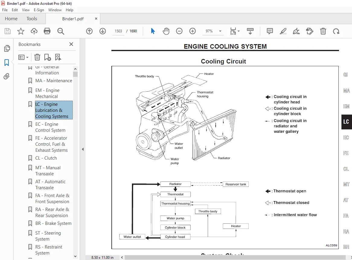
ENGINE COOLING SYSTEM1503
Cooling Circuit1503
System Check1503
Water Pump1505
Thermostat1507
Radiator1508
Overheating Cause Analysis1509
SERVICE DATA AND SPECIFICATIONS (SDS)1510
Engine Lubrication System1510
Engine Cooling System1510
ma1511
QUICK REFERENCE INDEX 0
Table of Contents1511
PRECAUTIONS AND PREPARATION1512
Supplemental Restraint System (SRS) ‘‘AIR BAG’’ and ‘‘SEAT BELT PRE-TENSIONER’’1512
Special Service Tool1512
Commercial Service Tool1512
Untitled1512
GENERAL MAINTENANCE1513
PERIODIC MAINTENANCE1515
Schedule 1 1516
Schedule 21517
RECOMMENDED FLUIDS AND LUBRICANTS1518
Fluids and Lubricants1518
SAE Viscosity Number1518
Antifreeze Coolant Mixture Ratio1519
ENGINE MAINTENANCE1520
Checking Drive Belts1520
Changing Engine Coolant1521
Checking Fuel Lines1522
Changing Fuel Filter1523
Changing Air Cleaner Filter1523
Changing Engine Oil1524
Changing Oil Filter1524
Changing Spark Plugs1525
Checking EVAP Vapor Purge Lines1526
CHASSIS AND BODY MAINTENANCE1527
Checking Exhaust System1527
Checking Clutch Fluid Level and Leaks1527
Checking M/T Oil1527
Changing M/T Oil1527
Checking A/T Fluid1528
Changing A/T Fluid1528
Checking Brake Fluid Level and Leaks1529
Checking Brake System1529
Checking Disc Brake1529
Checking Drum Brake1529
Balancing Wheels1531
Tire Rotation1531
Checking Steering Gear and Linkage1531
Checking Power Steering Fluid and Lines1531
Lubricating Locks, Hinges and Hood Latches1532
Checking Seat Belts, Buckles, Retractors, Anchors and Adjusters1532
SERVICE DATA AND SPECIFICATIONS (SDS)1533
Engine Maintenance1533
Chassis and Body Maintenance1533
mt1535
QUICK REFERENCE INDEX 0
Table of Contents1535
PREPARATION1536
Special Service Tools1536
Commercial Service Tools1538
NOISE, VIBRATION AND HARSHNESS (NVH) TROUBLESHOOTING 1539
NVH Troubleshooting Chart1539
MANUAL TRANSAXLE1539
DESCRIPTION1540
Cross-sectional View1540
ON-VEHICLE SERVICE1541
Replacing Oil Seal1541
Position Switch Check1542
REMOVAL AND INSTALLATION1543
Removal1543
Installation1546
TRANSAXLE GEAR CONTROL1547
MAJOR OVERHAUL1548
Case Components1548
Gear Components1549
Shift Control Components1550
DISASSEMBLY1551
REPAIR FOR COMPONENT PARTS1554
Input Shaft and Gears1554
Mainshaft and Gears1559
Final Drive1563
Shift Control Components1565
Case Components1565
ADJUSTMENT1567
Input Shaft End Play and Differential Side Bearing Preload1567
Mainshaft Bearing Preload1568
ASSEMBLY1571
SERVICE DATA AND SPECIFICATIONS (SDS)1575
General Specifications1575
Inspection and Adjustment1576
ra1581
QUICK REFERENCE INDEX 0
Table of Contents1581
PRECAUTIONS AND PREPARATION1582
Precautions1582
Special Service Tool1582
Commercial Service Tools1582
NOISE, VIBRATION AND HARSHNESS (NVH) TROUBLESHOOTING1583
NVH Troubleshooting Chart1583
REAR SUSPENSION SYSTEM1584
ON-VEHICLE SERVICE1585
Rear Axle and Rear Suspension Parts1585
Rear Wheel Bearing1586
Rear Wheel Alignment1586
REAR AXLE1588
Wheel Hub1588
REAR SUSPENSION1590
Removal and Installation1591
Coil Spring and Strut Assembly1592
Parallel Link, Radius Link and Stabilizer Bar1594
SERVICE DATA AND SPECIFICATIONS (SDS)1595
General Specifications1595
Inspection and Adjustment1595
rs1597
QUICK REFERENCE INDEX 0
Table of Contents1597
PRECAUTION1598
SUPPLEMENTAL RESTRAINT SYSTEM (SRS) “AIR BAG” AND “SEAT BELT PRE-TENSIONER”1598
SEAT BELTS1599
Precaution for Seat Belt Service1599
After A Collision1599
Front Seat Belt1600
Rear Seat Belt1602
Seat Belt Inspection1604
SUPPLEMENTAL RESTRAINT SYSTEM (SRS)1607
Precautions for SRS “AIR BAG” and “SEAT BELT PRE-TENSIONER” Service1607
Special Service Tools1607
Description1608
Seat Belt Pre-tensioner with Load Limiter1608
Built-in Type Side Air Bag1609
SRS Component Parts Location1609
Maintenance Items1610
Removal and Installation — Diagnosis Sensor Unit, Seat Belt Pre-tensioner and Satellite Sensor1612
Removal — Air Bag Module and Spiral Cable1614
Removal — Front Passenger Air Bag Module1615
Removal — Side Air Bag Module1617
Installation — Air Bag Module and Spiral Cable1618
Installation — Front Passenger Air Bag Module1619
Installation — Side Air Bag Module1620
Disposal of Air Bag Module and Seat Belt Pre-tensioner1620
Deployment of Side Air Bag Module (Built-in type) (Outside of vehicle)1623
DEPLOYMENT PROCEDURES FOR SEAT BELT PRE-TENSIONER (OUTSIDE OF VEHICLE)1624
TROUBLE DIAGNOSES — Supplemental Restraint System (SRS)1627
Trouble Diagnoses Introduction1627
How to Perform Trouble Diagnoses for Quick and Accurate Repair1629
Schematic1631
Wiring Diagram — SRS —1632
Self-diagnosis1636
Trouble Diagnoses for Air Bag Warning Lamp1656
Trouble Diagnosis for Seat Belt Pre-tensioner Warning Lamp1658
COLLISION DIAGNOSIS1660
FOR SIDE COLLISION1662
SRS Inspection (For side collision)1662
SUPER MULTIPLE JUNCTION (SMJ) 0
FUSE BLOCK — Junction Box (J/B) 2
FUSE AND FUSIBLE LINK BOX 3
ELECTRICAL UNITS 4
JOINT CONNECTOR (J/C) 5
st1665
QUICK REFERENCE INDEX 0
Table of Contents1665
PRECAUTIONS AND PREPARATION1666
Supplemental Restraint System (SRS) ‘‘AIR BAG’’ and ‘‘SEAT BELT PRE-TENSIONER’’1666
Precautions for Steering System1666
Special Service Tools1667
Commercial Service Tools1668
NOISE, VIBRATION AND HARSHNESS (NVH) TROUBLESHOOTING1669
NVH Troubleshooting Chart1669
ON-VEHICLE SERVICE1670
Checking and Adjusting Drive Belts1670
Checking Fluid Level1670
Checking Fluid Leakage1670
Bleeding Hydraulic System1671
Checking Steering Wheel Turning Force1671
Checking Steering Wheel Play1672
Checking Neutral Position on Steering Wheel1672
Front Wheel Turning Angle1672
Checking Gear Housing Movement1672
Checking Hydraulic System1673
STEERING WHEEL AND STEERING COLUMN1674
Steering Wheel1674
Steering Column1675
Disassembly and Assembly1676
Inspection1677
POWER STEERING GEAR AND LINKAGE1678
Removal and Installation1678
Disassembly1681
Inspection1681
Assembly1682
POWER STEERING PUMP1684
Pre-disassembly Inspection1684
Inspection1685
Disassembly1685
Assembly1686
SERVICE DATA AND SPECIFICATIONS (SDS)1688
General Specifications1688
Inspection and Adjustment1688
PLEASE NOTE:
- This is the same manual used by the dealers to diagnose and troubleshoot your vehicle
- You will be directed to the download page as soon as the purchase is completed. The whole payment and downloading process will take anywhere between 2-5 minutes
- Need any other service / repair / parts manual, please feel free to contact [email protected] . We still have 50,000 manuals unlisted
G.P