2000 NISSAN FRONTIER D22 Series(3.3L VG Engine) Service Manual PDF DOWNLOAD
$19.95
2000 NISSAN FRONTIER D22 Series(3.3L VG Engine) Service Manual PDF DOWNLOAD
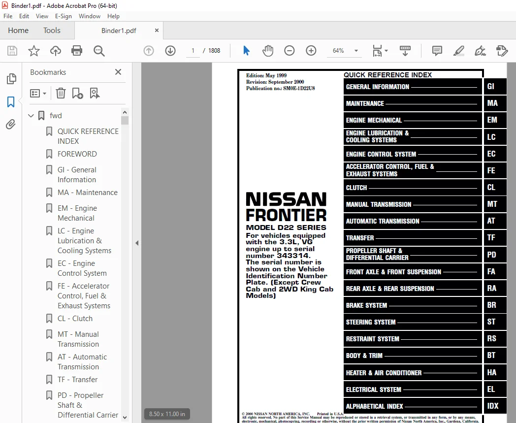
NISSAN FRONTIER MODEL D22 SERIES For vehicles equipped with the 3.3L, VG engine up to serial number 343314. The serial number is shown on the Vehicle Identification Number Plate. (Except Crew Cab and 2WD King Cab Models)
Description
2000 NISSAN FRONTIER D22 Series(3.3L VG Engine) Service Manual PDF DOWNLOAD
FILE DETAILS:
2000 NISSAN FRONTIER D22 Series(3.3L VG Engine) Service Manual PDF DOWNLOAD
Language : English
Pages : 1808
Downloadable : Yes
File Type : PDF
IMAGES PREVIEW OF THE MANUAL:
Customer Support: [email protected]
https://vimeo.com/851882617?share=copy
DESCRIPTION:
2000 NISSAN FRONTIER D22 Series(3.3L VG Engine) Service Manual PDF DOWNLOAD
FOREWORD
- This manual contains maintenance and repair procedures for the 2000 Nissan FRONTIER equipped with the 3.3L, VG engine. (Except Crew Cab and 2WD King Cab Models)
- In order to assure your safety and the efficient functioning of the vehicle, this manual should be read thoroughly.
- It is especially important that the PRECAUTIONS in the GI section be completely understood before starting any repair task.
- All information in this manual is based on the latest product information at the time of publication. The right is reserved to make changes in specifications and methods at any time without notice.
IMPORTANT SAFETY NOTICE
- The proper performance of service is essential for both the safety of the technician and the efficient functioning of the vehicle.
- The service methods in this Service Manual are described in such a manner that the service may be performed safely and accurately.
- Service varies with the procedures used, the skills of the technician and the tools and parts available.
- Accordingly, anyone using service procedures, tools or parts which are not specifically recommended by NISSAN must first be completely satisfied that neither personal safety nor the vehicle’s safety will be jeopardized by the service method selected.
TABLE OF CONTENTS:
2000 NISSAN FRONTIER D22 Series(3.3L VG Engine) Service Manual PDF DOWNLOAD
NISSAN FRONTIER MODEL D22 SERIES For vehicles equipped with the 3.3L, VG engine up to serial number 343314. The serial number is shown on the Vehicle Identification Number Plate. (Except Crew Cab and 2WD King Cab Models)
fwd........................................................................................................................   1
	QUICK REFERENCE INDEX..................................................................................................   1
	FOREWORD...............................................................................................................   2
	GI - General Information...............................................................................................   0
	MA - Maintenance.......................................................................................................   0
	EM - Engine Mechanical.................................................................................................   0
	LC - Engine Lubrication & Cooling Systems..............................................................................   0
	EC - Engine Control System.............................................................................................   0
	FE - Accelerator Control, Fuel & Exhaust Systems.......................................................................   0
	CL - Clutch............................................................................................................   0
	MT - Manual Transmission...............................................................................................   0
	AT - Automatic Transmission............................................................................................   0
	TF - Transfer..........................................................................................................   0
	PD - Propeller Shaft & Differential Carrier............................................................................   0
	FA - Front Axle & Front Suspension.....................................................................................   0
	RA - Rear Axle & Rear Suspension.......................................................................................   0
	BR - Brake System......................................................................................................   0
	ST - Steering System...................................................................................................   0
	RS - Restraint System..................................................................................................   0
	BT - Body & Trim.......................................................................................................   0
	HA - Heater & Air Conditioner..........................................................................................   0
	EL - Electrical System.................................................................................................   0
	IDX - Alphabetical Index...............................................................................................   1
	SUPER MULTIPLE JUNCTION (SMJ)..........................................................................................   0
	FUSE BLOCK — Junction Box (J/B)........................................................................................   2
	FUSE AND FUSIBLE LINK BOX..............................................................................................   3
	ELECTRICAL UNITS.......................................................................................................   4
	JOINT CONNECTOR (J/C)..................................................................................................   5
	QUICK REFERENCE CHART..................................................................................................   6
	COMMENT SHEET..........................................................................................................   3
	GST Mode 6 - Test Value & Test Limit Chart.............................................................................   5
at.........................................................................................................................   6
	QUICK REFERENCE INDEX..................................................................................................   0
	Table of Contents......................................................................................................   6
	TROUBLE DIAGNOSIS - INDEX..............................................................................................   9
		Alphabetical & P No. Index for DTC.................................................................................   9
	PRECAUTIONS............................................................................................................  11
		Precautions for Supplemental Restraint System (SRS) "AIR BAG"......................................................  11
		Precautions for On Board Diagnostic (OBD) System of A/T and Engine.................................................  11
		Precautions........................................................................................................  12
		Service Notice or Precautions......................................................................................  13
		Wiring Diagrams and Trouble Diagnosis..............................................................................  14
	PREPARATION............................................................................................................  15
		Special Service Tools..............................................................................................  15
	OVERALL SYSTEM.........................................................................................................  17
		A/T Electrical Parts Location......................................................................................  17
		Circuit Diagram....................................................................................................  18
		Cross-sectional View...............................................................................................  19
		Hydraulic Control Circuit..........................................................................................  20
		Shift Mechanism....................................................................................................  21
		Control System.....................................................................................................  30
		Control Mechanism..................................................................................................  31
		Control Valve......................................................................................................  36
	ON BOARD DIAGNOSTIC SYSTEM DESCRIPTION.................................................................................  38
		Introduction.......................................................................................................  38
		OBD-II Function for A/T System.....................................................................................  38
		One or Two Trip Detection Logic of OBD-II..........................................................................  38
		OBD-II Diagnostic Trouble Code (DTC)...............................................................................  38
		Malfunction Indicator Lamp (MIL)...................................................................................  42
		CONSULT............................................................................................................  42
		Diagnostic Procedure Without CONSULT...............................................................................  51
	TROUBLE DIAGNOSIS - INTRODUCTION.......................................................................................  58
		Introduction.......................................................................................................  58
		Work Flow..........................................................................................................  62
	TROUBLE DIAGNOSIS - BASIC INSPECTION...................................................................................  64
		A/T Fluid Check....................................................................................................  64
		Stall Test.........................................................................................................  64
		Line Pressure Test.................................................................................................  67
		Road Test..........................................................................................................  68
	TROUBLE DIAGNOSIS - GENERAL DESCRIPTION................................................................................  86
		Symptom Chart......................................................................................................  86
		TCM Terminals and Reference Value..................................................................................  97
	TROUBLE DIAGNOSIS FOR POWER SUPPLY..................................................................................... 101
		Wiring Diagram - AT - MAIN......................................................................................... 101
	DTC P0705 PARK/NEUTRAL POSITION SWITCH................................................................................. 104
		Description........................................................................................................ 104
		Wiring Diagram - AT - PNP/SW....................................................................................... 106
		Diagnostic Procedure............................................................................................... 107
		Component Inspection............................................................................................... 109
	DTC P0710 A/T FLUID TEMPERATURE SENSOR CIRCUIT......................................................................... 110
		Description........................................................................................................ 110
		Wiring Diagram - AT - FTS.......................................................................................... 112
		Diagnostic Procedure............................................................................................... 113
		Component Inspection............................................................................................... 115
	DTC P0720 VEHICLE SPEED SENSOR.A/T (REVOLUTION SENSOR)................................................................. 116
		Description........................................................................................................ 116
		Wiring Diagram - AT - VSSA/T....................................................................................... 118
		Diagnostic Procedure............................................................................................... 119
		Component Inspection............................................................................................... 120
	DTC P0725 ENGINE SPEED SIGNAL.......................................................................................... 121
		Description........................................................................................................ 121
		Wiring Diagram - AT - ENGSS........................................................................................ 123
		Diagnostic Procedure............................................................................................... 124
	DTC P0731 IMPROPER SHIFTING TO 1ST GEAR POSITION....................................................................... 126
		Description........................................................................................................ 126
		Wiring Diagram - AT - 1ST.......................................................................................... 129
		Diagnostic Procedure............................................................................................... 130
		Component Inspection............................................................................................... 131
	DTC P0732 IMPROPER SHIFTING TO 2ND GEAR POSITION....................................................................... 132
		Description........................................................................................................ 132
		Wiring Diagram - AT - 2ND.......................................................................................... 135
		Diagnostic Procedure............................................................................................... 136
		Component Inspection............................................................................................... 137
	DTC P0733 IMPROPER SHIFTING TO 3RD GEAR POSITION....................................................................... 138
		Description........................................................................................................ 138
		Wiring Diagram - AT - 3RD.......................................................................................... 141
		Diagnostic Procedure............................................................................................... 142
		Component Inspection............................................................................................... 143
	DTC P0734 IMPROPER SHIFTING TO 4TH GEAR POSITION....................................................................... 144
		Description........................................................................................................ 144
		Wiring Diagram - AT - 4TH.......................................................................................... 148
		Diagnostic Procedure............................................................................................... 149
		Component Inspection............................................................................................... 154
	DTC P0740 TORQUE CONVERTER CLUTCH SOLENOID VALVE....................................................................... 155
		Description........................................................................................................ 155
		Wiring Diagram - AT - TCV.......................................................................................... 157
		Diagnostic Procedure............................................................................................... 158
		Component Inspection............................................................................................... 159
	DTC P0744 IMPROPER LOCK-UP OPERATION................................................................................... 160
		Description........................................................................................................ 160
		Wiring Diagram - AT - TCCSIG....................................................................................... 163
		Diagnostic Procedure............................................................................................... 164
		Component Inspection............................................................................................... 169
	DTC P0745 LINE PRESSURE SOLENOID VALVE................................................................................. 170
		Description........................................................................................................ 170
		Wiring Diagram - AT - LPSV......................................................................................... 172
		Diagnostic Procedure............................................................................................... 173
		Component Inspection............................................................................................... 174
	DTC P0750 SHIFT SOLENOID VALVE A....................................................................................... 176
		Description........................................................................................................ 176
		Wiring Diagram - AT - SSV/A........................................................................................ 178
		Diagnostic Procedure............................................................................................... 179
		Component Inspection............................................................................................... 180
	DTC P0755 SHIFT SOLENOID VALVE B....................................................................................... 181
		Description........................................................................................................ 181
		Wiring Diagram - AT - SSV/B........................................................................................ 183
		Diagnostic Procedure............................................................................................... 184
		Component Inspection............................................................................................... 185
	DTC P1705 THROTTLE POSITION SENSOR..................................................................................... 186
		Description........................................................................................................ 186
		Wiring Diagram - AT - TPS.......................................................................................... 189
		Diagnostic Procedure............................................................................................... 190
		Component Inspection............................................................................................... 194
	DTC P1760 OVERRUN CLUTCH SOLENOID VALVE................................................................................ 195
		Description........................................................................................................ 195
		Wiring Diagram - AT - OVRCSV....................................................................................... 197
		Diagnostic Procedure............................................................................................... 198
		Component Inspection............................................................................................... 199
	DTC BATT/FLUID TEMP SEN (A/T FLUID TEMP SENSOR CIRCUIT AND TCM POWER SOURCE)........................................... 200
		Description........................................................................................................ 200
		Wiring Diagram - AT - BA/FTS....................................................................................... 202
		Diagnostic Procedure............................................................................................... 203
		Component Inspection............................................................................................... 205
	VEHICLE SPEED SENSOR.MTR............................................................................................... 206
		Description........................................................................................................ 206
		Wiring Diagram - AT - VSSMTR....................................................................................... 208
		Diagnostic Procedure............................................................................................... 209
	DTC CONTROL UNIT (RAM), CONTROL UNIT (ROM)............................................................................. 210
		Description........................................................................................................ 210
		Diagnostic Procedure............................................................................................... 211
	DTC CONTROL UNIT (EEPROM).............................................................................................. 212
		Description........................................................................................................ 212
		Diagnostic Procedure............................................................................................... 213
	TROUBLE DIAGNOSES FOR SYMPTOMS......................................................................................... 214
		Wiring Diagram - AT - NONDTC....................................................................................... 214
		1. O/D OFF Indicator Lamp Does Not Come On......................................................................... 217
		2. Engine Cannot Be Started In P and N Position.................................................................... 219
		3. In "P" Position, Vehicle Moves Forward Or Backward When Pushed.................................................. 220
		4. In N Position, Vehicle Moves.................................................................................... 221
		5. Large Shock. N -> R Position.................................................................................... 223
		6. Vehicle Does Not Creep Backward In R Position................................................................... 225
		7. Vehicle Does Not Creep Forward In D, 2 Or 1 Position............................................................ 228
		8. Vehicle Cannot Be Started From D1............................................................................... 231
		9. A/T Does Not Shift: D1 -> D2 Or Does Not Kickdown: D4 -> D2..................................................... 234
		10. A/T Does Not Shift: D2 -> D3................................................................................... 237
		11. A/T Does Not Shift: D3 -> D4................................................................................... 240
		12. A/T Does Not Perform Lock-up................................................................................... 243
		13. A/T Does Not Hold Lock-up Condition............................................................................ 245
		14. Lock-up Is Not Released........................................................................................ 247
		15. Engine Speed Does Not Return To Idle (Light Braking D4 -> D3).................................................. 248
		16. Vehicle Does Not Start From D1................................................................................. 250
		17. A/T Does Not Shift: D4 -> D3, When Overdrive Control Switch ON -> OFF.......................................... 251
		18. A/T Does Not Shift: D3 -> 22, When Selector Lever D -> 2 Position.............................................. 252
		19. A/T Does Not Shift: 22 -> 11, When Selector Lever 2 -> 1 Position.............................................. 253
		20. Vehicle Does Not Decelerate By Engine Brake.................................................................... 254
		21. TCM Self-diagnosis Does Not Activate (PNP, Overdrive Control and Throttle Position Switches Circuit Checks).... 254
	A/T SHIFT LOCK SYSTEM.................................................................................................. 262
		Description........................................................................................................ 262
		Wiring Diagram - SHIFT -........................................................................................... 263
		Diagnostic Procedure............................................................................................... 264
		Component Check.................................................................................................... 266
	KEY INTERLOCK CABLE.................................................................................................... 267
		Components......................................................................................................... 267
		Removal............................................................................................................ 267
		Installation....................................................................................................... 268
	ON-VEHICLE SERVICE..................................................................................................... 269
		Control Valve Assembly and Accumulators............................................................................ 269
		Revolution Sensor Replacement...................................................................................... 270
		Rear Oil Seal Replacement.......................................................................................... 270
		Parking Components Inspection...................................................................................... 270
		Park/Neutral Position (PNP) Switch Adjustment...................................................................... 270
		Manual Control Linkage Adjustment.................................................................................. 271
	REMOVAL AND INSTALLATION............................................................................................... 272
		Removal............................................................................................................ 272
		Installation....................................................................................................... 273
	OVERHAUL............................................................................................................... 275
		Components......................................................................................................... 275
		Oil Channel........................................................................................................ 277
		Locations of Needle Bearings, Thrust Washers and Snap Rings........................................................ 278
	DISASSEMBLY............................................................................................................ 279
	REPAIR FOR COMPONENT PARTS............................................................................................. 290
		Oil Pump........................................................................................................... 290
		Control Valve Assembly............................................................................................. 294
		Control Valve Upper Body........................................................................................... 300
		Control Valve Lower Body........................................................................................... 305
		Reverse Clutch..................................................................................................... 307
		High Clutch........................................................................................................ 311
		Forward and Overrun Clutches....................................................................................... 313
		Low & Reverse Brake................................................................................................ 317
		Forward Clutch Drum Assembly....................................................................................... 321
		Rear Internal Gear and Forward Clutch Hub.......................................................................... 323
		Band Servo Piston Assembly......................................................................................... 326
		Parking Pawl Components............................................................................................ 330
	ASSEMBLY............................................................................................................... 332
		Assembly (1)....................................................................................................... 332
		Adjustment......................................................................................................... 339
		Assembly (2)....................................................................................................... 342
	SERVICE DATA AND SPECIFICATIONS (SDS).................................................................................. 349
		General Specifications............................................................................................. 349
		Shift Schedule..................................................................................................... 349
		Stall Revolution................................................................................................... 349
		Line Pressure...................................................................................................... 349
		Return Springs..................................................................................................... 350
		Accumulator O-ring................................................................................................. 351
		Clutches and Brakes................................................................................................ 351
		Oil Pump and Low One-way Clutch.................................................................................... 353
		Total End Play..................................................................................................... 353
		Reverse Clutch Drum End Play....................................................................................... 354
		Removal and Installation........................................................................................... 354
	SUPER MULTIPLE JUNCTION (SMJ)..........................................................................................   0
	FUSE BLOCK — Junction Box (J/B)........................................................................................   2
	FUSE AND FUSIBLE LINK BOX..............................................................................................   3
	ELECTRICAL UNITS.......................................................................................................   4
	JOINT CONNECTOR (J/C)..................................................................................................   5
br......................................................................................................................... 356
	QUICK REFERENCE INDEX..................................................................................................   0
	Table of Contents...................................................................................................... 356
	PRECAUTIONS AND PREPARATION............................................................................................ 358
		Supplemental Restraint System (SRS) ‘‘AIR BAG’’ GI................................................................. 358
		Precautions for Brake System....................................................................................... 359
		Commercial Service Tools........................................................................................... 359
	NOISE, VIBRATION AND HARSHNESS (NVH) TROUBLESHOOTING................................................................... 360
		NVH Troubleshooting Chart.......................................................................................... 360
	ON-VEHICLE SERVICE..................................................................................................... 361
		Checking Brake Fluid Level......................................................................................... 361
		Checking Brake Line................................................................................................ 361
		Changing Brake Fluid............................................................................................... 361
		Brake Burnishing Procedure......................................................................................... 361
		Bleeding Brake System.............................................................................................. 362
	BRAKE HYDRAULIC LINE................................................................................................... 363
	BRAKE HYDRAULIC LINE/CONTROL VALVE..................................................................................... 365
		Proportioning Valve................................................................................................ 365
	BRAKE PEDAL AND BRACKET................................................................................................ 366
		Removal and Installation........................................................................................... 366
		Inspection......................................................................................................... 367
		Adjustment......................................................................................................... 367
	MASTER CYLINDER........................................................................................................ 368
		Removal............................................................................................................ 368
		Disassembly........................................................................................................ 369
		Inspection......................................................................................................... 369
		Assembly........................................................................................................... 369
		Installation....................................................................................................... 370
	BRAKE BOOSTER.......................................................................................................... 371
		On-vehicle Service................................................................................................. 371
		Removal............................................................................................................ 371
		Inspection......................................................................................................... 371
		Installation....................................................................................................... 372
	VACUUM HOSE............................................................................................................ 373
		Removal and Installation........................................................................................... 373
		Inspection......................................................................................................... 373
	FRONT DISC BRAKE....................................................................................................... 374
		Pad Replacement.................................................................................................... 374
		Removal............................................................................................................ 375
		Disassembly........................................................................................................ 376
		Inspection — Caliper............................................................................................... 376
		Inspection — Rotor................................................................................................. 376
		Assembly........................................................................................................... 377
		Installation....................................................................................................... 377
	REAR DRUM BRAKE........................................................................................................ 378
		Removal............................................................................................................ 379
		Inspection — Wheel Cylinder........................................................................................ 380
		Wheel Cylinder Overhaul............................................................................................ 380
		Inspection — Drum.................................................................................................. 380
		Inspection — Lining................................................................................................ 380
		Installation....................................................................................................... 380
	PARKING BRAKE CONTROL.................................................................................................. 382
		Removal and Installation........................................................................................... 383
		Inspection......................................................................................................... 383
		Adjustment......................................................................................................... 383
	ANTI-LOCK BRAKE SYSTEM................................................................................................. 384
		Purpose............................................................................................................ 384
		Operation.......................................................................................................... 384
		ABS Hydraulic Circuit.............................................................................................. 384
		System Components.................................................................................................. 385
		System Description................................................................................................. 385
		Removal and Installation........................................................................................... 387
	TROUBLE DIAGNOSES...................................................................................................... 390
		How to Perform Trouble Diagnoses for Quick and Accurate Repair GI.................................................. 390
		Preliminary Check.................................................................................................. 392
		Component Parts and Harness Connector Location..................................................................... 393
		Schematic.......................................................................................................... 394
		Wiring Diagram — ABS —............................................................................................. 395
		Self-diagnosis..................................................................................................... 398
		CONSULT............................................................................................................ 401
		CONSULT Inspection Procedure....................................................................................... 402
		Ground Circuit Check............................................................................................... 407
	TROUBLE DIAGNOSES FOR SELF-DIAGNOSTIC ITEMS............................................................................ 408
		Diagnostic Procedure 1 (Wheel sensor or rotor)..................................................................... 408
		Diagnostic Procedure 2 (ABS actuator solenoid valve and solenoid valve relay)...................................... 410
		Diagnostic Procedure 3 (Motor relay or motor)...................................................................... 412
		Diagnostic Procedure 4 (Low voltage)............................................................................... 414
		Diagnostic Procedure 5 (G sensor).................................................................................. 415
		Diagnostic Procedure 6 (Control unit).............................................................................. 416
	TROUBLE DIAGNOSES FOR SYMPTOMS......................................................................................... 417
		Diagnostic Procedure 7 (ABS works frequently.)..................................................................... 417
		Diagnostic Procedure 8 (Unexpected pedal action)................................................................... 418
		Diagnostic Procedure 9 (Long stopping distance).................................................................... 418
		Diagnostic Procedure 10 (ABS does not work.)....................................................................... 419
		Diagnostic Procedure 11 (Pedal vibration and noise)................................................................ 419
		Diagnostic Procedure 12 (Warning lamp does not come on when ignition switch is turned ON.)......................... 420
		Diagnostic Procedure 13 (Warning lamp stays on when ignition switch is turned ON.)................................. 422
		Electrical Components Inspection................................................................................... 424
	SERVICE DATA AND SPECIFICATIONS (SDS).................................................................................. 425
		General Specifications............................................................................................. 425
		Inspection and Adjustment.......................................................................................... 426
	SUPER MULTIPLE JUNCTION (SMJ)..........................................................................................   0
	FUSE BLOCK — Junction Box (J/B)........................................................................................   2
	FUSE AND FUSIBLE LINK BOX..............................................................................................   3
	ELECTRICAL UNITS.......................................................................................................   4
	JOINT CONNECTOR (J/C)..................................................................................................   5
bt......................................................................................................................... 428
	QUICK REFERENCE INDEX..................................................................................................   0
	Table of Contents...................................................................................................... 428
	PRECAUTIONS AND PREPARATION............................................................................................ 430
		Service Notice..................................................................................................... 430
		Supplemental Restraint System (SRS) ‘‘AIR BAG’’.................................................................... 430
	PREPARATION............................................................................................................ 431
		Special Service Tools.............................................................................................. 431
		Commercial Service Tools........................................................................................... 431
	SQUEAK AND RATTLE TROUBLE DIAGNOSES.................................................................................... 432
		Work Flow.......................................................................................................... 432
			CUSTOMER INTERVIEW............................................................................................. 432
			DUPLICATE THE NOISE AND TEST DRIVE............................................................................. 433
			CHECK RELATED SERVICE BULLETINS................................................................................ 433
			LOCATE THE NOISE AND IDENTIFY THE ROOT CAUSE................................................................... 433
			REPAIR THE CAUSE............................................................................................... 433
			CONFIRM THE REPAIR............................................................................................. 434
		Generic Squeak and Rattle Troubleshooting.......................................................................... 434
			INSTRUMENT PANEL............................................................................................... 434
			CENTER CONSOLE................................................................................................. 434
			DOORS.......................................................................................................... 434
			TRUNK.......................................................................................................... 434
			SUNROOF AND HEADLINER.......................................................................................... 434
			SEATS.......................................................................................................... 435
			UNDERHOOD...................................................................................................... 435
		Diagnostic Worksheet............................................................................................... 436
	GENERAL SERVICING...................................................................................................... 438
		Clip and Fastener.................................................................................................. 438
	BODY END............................................................................................................... 440
		Body Front End..................................................................................................... 440
			REMOVAL — Front bumper assembly................................................................................ 440
		Body Rear End...................................................................................................... 443
			REMOVAL — Rear bumper assembly................................................................................. 443
	DOOR................................................................................................................... 445
		Front Door......................................................................................................... 445
	INSTRUMENT PANEL....................................................................................................... 446
		REMOVAL — Instrument panel assembly................................................................................ 446
	INTERIOR TRIM.......................................................................................................... 449
		Side and Floor Trim................................................................................................ 449
			REMOVAL — Body side trim....................................................................................... 449
				King cab model............................................................................................. 449
				Standard cab model......................................................................................... 449
		Door Trim.......................................................................................................... 452
			REMOVAL........................................................................................................ 452
				Door trim (Formed type).................................................................................... 452
		Roof Trim.......................................................................................................... 455
			REMOVAL — Headlining........................................................................................... 455
	EXTERIOR............................................................................................................... 457
		1  Hood front sealing rubber....................................................................................... 458
		2 Cowl top seal and cowl top grille................................................................................ 458
		3 Windshield side molding.......................................................................................... 458
		4 Windshield upper molding......................................................................................... 458
		5 Sunroof weatherstrip and lid protector........................................................................... 458
		6 Drip weatherstrip................................................................................................ 459
		7 Body side welt................................................................................................... 459
		8 Door weatherstrip................................................................................................ 459
		9 Door outside molding............................................................................................. 459
		10 Drafter duct.................................................................................................... 460
		11 Over fender..................................................................................................... 460
		12 Rear combination lamp........................................................................................... 460
	SEAT................................................................................................................... 461
		Front Seat......................................................................................................... 461
		Jump Seat — King Cab Model......................................................................................... 463
	SUNROOF................................................................................................................ 464
	WINDSHIELD AND WINDOWS................................................................................................. 465
		Windshield......................................................................................................... 466
		Side Window........................................................................................................ 466
		Back Window........................................................................................................ 467
		Rearview Mirror.................................................................................................... 468
	MIRROR................................................................................................................. 469
		Door Mirror........................................................................................................ 469
			REMOVAL — Door mirror.......................................................................................... 469
	CAB AND REAR BODY...................................................................................................... 470
		Body Mounting...................................................................................................... 470
	BODY ALIGNMENT......................................................................................................... 471
		Engine Compartment................................................................................................. 472
			MEASUREMENT.................................................................................................... 472
			MEASUREMENT POINTS............................................................................................. 473
		Underbody.......................................................................................................... 474
			MEASUREMENT.................................................................................................... 474
				2WD 4WD (Short wheelbase) models........................................................................... 474
			MEASUREMENT POINTS............................................................................................. 475
				2WD 4WD (Short wheelbase) models........................................................................... 475
			MEASUREMENT.................................................................................................... 476
				2WD 4WD (Long wheelbase) models............................................................................ 476
			MEASUREMENT POINTS............................................................................................. 477
				2WD 4WD (Long wheelbase) models............................................................................ 477
cl......................................................................................................................... 478
	QUICK REFERENCE INDEX..................................................................................................   0
	Table of Contens....................................................................................................... 478
	PRECAUTIONS AND PREPARATION............................................................................................ 479
		Precautions........................................................................................................ 479
		Special Service Tools.............................................................................................. 479
		Commercial Service Tools........................................................................................... 479
	NOISE, VIBRATION AND HARSHNESS (NVH) TROUBLESHOOTING................................................................... 480
		NVH Troubleshooting Chart.......................................................................................... 480
	CLUTCH SYSTEM.......................................................................................................... 481
		Clutch Pedal....................................................................................................... 482
	INSPECTION AND ADJUSTMENT.............................................................................................. 483
		Adjusting Clutch Pedal............................................................................................. 483
		Air Bleeding Procedure............................................................................................. 484
	HYDRAULIC CLUTCH CONTROL............................................................................................... 485
		Clutch Master Cylinder (With clutch damper)........................................................................ 485
		Operating Cylinder................................................................................................. 486
	CLUTCH RELEASE MECHANISM............................................................................................... 487
	CLUTCH DISC AND CLUTCH COVER........................................................................................... 489
		Clutch Disc........................................................................................................ 489
		Clutch Cover and Flywheel.......................................................................................... 490
	SERVICE DATA AND SPECIFICATIONS (SDS).................................................................................. 491
		General Specifications............................................................................................. 491
			Clutch Control System.......................................................................................... 491
		Inspection and Adjustment.......................................................................................... 491
ec......................................................................................................................... 492
	QUICK REFERENCE INDEX..................................................................................................   0
	Table of Contents...................................................................................................... 492
	TROUBLE DIAGNOSIS - INDEX.............................................................................................. 499
		Alphabetical & P No. Index for DTC................................................................................. 499
	PRECAUTIONS............................................................................................................ 505
		Supplemental Restraint System (SRS) "AIR BAG"...................................................................... 505
		Precautions for On Board Diagnostic (OBD) System of Engine and A/T................................................. 505
		Engine Fuel & Emission Control System.............................................................................. 506
		Precautions........................................................................................................ 507
		Wiring Diagrams and Trouble Diagnosis.............................................................................. 508
	PREPARATION............................................................................................................ 509
		Special Service Tools.............................................................................................. 509
		Commercial Service Tools........................................................................................... 509
	ENGINE AND EMISSION CONTROL OVERALL SYSTEM............................................................................. 511
		Engine Control Component Parts Location............................................................................ 511
		Circuit Diagram.................................................................................................... 513
		System Diagram..................................................................................................... 514
		Vacuum Hose Drawing................................................................................................ 515
		System Chart....................................................................................................... 516
	ENGINE AND EMISSION BASIC CONTROL SYSTEM DESCRIPTION................................................................... 517
		Multiport Fuel Injection (MFI) System.............................................................................. 517
		Distributor Ignition (DI) System................................................................................... 519
		Air Conditioning Cut Control....................................................................................... 520
		Fuel Cut Control (at no load & high engine speed).................................................................. 521
		Evaporative Emission System........................................................................................ 521
		Positive Crankcase Ventilation..................................................................................... 527
	BASIC SERVICE PROCEDURE................................................................................................ 528
		Fuel Pressure Release.............................................................................................. 528
		Fuel Pressure Check................................................................................................ 528
		Fuel Pressure Regulator Check...................................................................................... 529
		Injector........................................................................................................... 529
		Fast Idle Cam (FIC)................................................................................................ 530
		Idle Speed/Ignition Timing/Idle Mixture Ratio Adjustment........................................................... 532
	ON BOARD DIAGNOSTIC SYSTEM DESCRIPTION................................................................................. 545
		Introduction....................................................................................................... 545
		Two Trip Detection Logic........................................................................................... 545
		Emission-related Diagnostic Information............................................................................ 546
		Malfunction Indicator Lamp (MIL)................................................................................... 558
		OBD System Operation Chart......................................................................................... 562
		CONSULT............................................................................................................ 567
		Generic Scan Tool (GST)............................................................................................ 581
	TROUBLE DIAGNOSIS - INTRODUCTION....................................................................................... 583
		Introduction....................................................................................................... 583
		Work Flow.......................................................................................................... 585
	TROUBLE DIAGNOSIS - BASIC INSPECTION................................................................................... 587
		Basic Inspection................................................................................................... 587
	TROUBLE DIAGNOSIS - GENERAL DESCRIPTION................................................................................ 604
		DTC Inspection Priority Chart...................................................................................... 604
		Fail-safe Chart.................................................................................................... 605
		Symptom Matrix Chart............................................................................................... 606
		CONSULT Reference Value in Data Monitor Mode....................................................................... 610
		Major Sensor Reference Graph in Data Monitor Mode.................................................................. 612
		ECM Terminals and Reference Value.................................................................................. 615
	TROUBLE DIAGNOSIS FOR INTERMITTENT INCIDENT............................................................................ 624
		Description........................................................................................................ 624
		Diagnostic Procedure............................................................................................... 624
	TROUBLE DIAGNOSIS FOR POWER SUPPLY..................................................................................... 625
		Main Power Supply and Ground Circuit............................................................................... 625
	DTC P0100 MASS AIR FLOW SENSOR (MAFS).................................................................................. 632
		Component Description.............................................................................................. 632
		CONSULT Reference Value in Data Monitor Mode....................................................................... 632
		ECM Terminals and Reference Value.................................................................................. 632
		On Board Diagnosis Logic........................................................................................... 632
		DTC Confirmation Procedure......................................................................................... 633
		Overall Function Check............................................................................................. 636
		Wiring Diagram..................................................................................................... 637
		Diagnostic Procedure............................................................................................... 638
		Component Inspection............................................................................................... 641
	DTC P0105 ABSOLUTE PRESSURE SENSOR..................................................................................... 642
		Component Description.............................................................................................. 642
		On Board Diagnosis Logic........................................................................................... 642
		DTC Confirmation Procedure......................................................................................... 642
		Overall Function Check............................................................................................. 644
		Wiring Diagram..................................................................................................... 645
		Diagnostic Procedure............................................................................................... 646
		Component Inspection............................................................................................... 652
	DTC P0110 INTAKE AIR TEMPERATURE SENSOR................................................................................ 654
		Component Description.............................................................................................. 654
		On Board Diagnosis Logic........................................................................................... 654
		DTC Confirmation Procedure......................................................................................... 654
		Wiring Diagram..................................................................................................... 657
		Diagnostic Procedure............................................................................................... 658
		Component Inspection............................................................................................... 659
	DTC P0115 ENGINE COOLANT TEMPERATURE SENSOR (ECTS) (CIRCUIT)........................................................... 661
		Component Description.............................................................................................. 661
		On Board Diagnosis Logic........................................................................................... 661
		DTC Confirmation Procedure......................................................................................... 662
		Wiring Diagram..................................................................................................... 663
		Diagnostic Procedure............................................................................................... 664
		Component Inspection............................................................................................... 665
	DTC P0120 THROTTLE POSITION SENSOR..................................................................................... 666
		Description........................................................................................................ 666
		CONSULT Reference Value in Data Monitor Mode....................................................................... 666
		ECM Terminals and Reference Value.................................................................................. 666
		On Board Diagnosis Logic........................................................................................... 667
		DTC Confirmation Procedure......................................................................................... 667
		Wiring Diagram..................................................................................................... 672
		Diagnostic Procedure............................................................................................... 673
		Component Inspection............................................................................................... 677
	DTC P0125 ENGINE COOLANT TEMPERATURE (ECT) SENSOR...................................................................... 679
		Description........................................................................................................ 679
		On Board Diagnosis Logic........................................................................................... 679
		DTC Confirmation Procedure......................................................................................... 679
		Wiring Diagram..................................................................................................... 681
		Diagnostic Procedure............................................................................................... 682
		Component Inspection............................................................................................... 683
	DTC P0130 (RIGHT, -B1), P0150 (LEFT, -B2) FRONT HO2S (CIRCUIT)......................................................... 684
		Component Description.............................................................................................. 684
		CONSULT Reference Value in Data Monitor Mode....................................................................... 684
		ECM Terminals and Reference Value.................................................................................. 684
		On Board Diagnosis Logic........................................................................................... 685
		DTC Confirmation Procedure......................................................................................... 685
		Overall Function Check............................................................................................. 686
		Wiring Diagram..................................................................................................... 687
		Diagnostic Procedure............................................................................................... 689
		Component Inspection............................................................................................... 691
	DTC P0131 (RIGHT, -B1), P0151 (LEFT, -B2) FRONT HO2S (LEAN SHIFT MONITORING)........................................... 693
		Component Description.............................................................................................. 693
		CONSULT Reference Value in Data Monitor Mode....................................................................... 693
		ECM Terminals and Reference Value.................................................................................. 693
		On Board Diagnosis Logic........................................................................................... 694
		DTC Confirmation Procedure......................................................................................... 694
		Overall Function Check............................................................................................. 695
		Diagnostic Procedure............................................................................................... 696
		Component Inspection............................................................................................... 698
	DTC P0132 (RIGHT, -B1), P0152 (LEFT, -B2) FRONT HO2S (RICH SHIFT MONITORING)........................................... 700
		Component Description.............................................................................................. 700
		CONSULT Reference Value in Data Monitor Mode....................................................................... 700
		ECM Terminals and Reference Value.................................................................................. 700
		On Board Diagnosis Logic........................................................................................... 701
		DTC Confirmation Procedure......................................................................................... 701
		Overall Function Check............................................................................................. 702
		Diagnostic Procedure............................................................................................... 703
		Component Inspection............................................................................................... 705
	DTC P0133 (RIGHT, -B1), P0153 (LEFT, -B2) FRONT HO2S (RESPONSE MONITORING)............................................. 707
		Component Description.............................................................................................. 707
		CONSULT Reference Value in Data Monitor Mode....................................................................... 707
		ECM Terminals and Reference Value.................................................................................. 707
		On Board Diagnosis Logic........................................................................................... 708
		DTC Confirmation Procedure......................................................................................... 708
		Overall Function Check............................................................................................. 709
		Wiring Diagram..................................................................................................... 710
		Diagnostic Procedure............................................................................................... 712
		Component Inspection............................................................................................... 716
	DTC P0134 (RIGHT, -B1), P0154 (LEFT, -B2) FRONT HO2S (HIGH VOLTAGE).................................................... 718
		Component Description.............................................................................................. 718
		CONSULT Reference Value in Data Monitor Mode....................................................................... 718
		ECM Terminals and Reference Value.................................................................................. 718
		On Board Diagnosis Logic........................................................................................... 719
		DTC Confirmation Procedure......................................................................................... 719
		Wiring Diagram..................................................................................................... 721
		Diagnostic Procedure............................................................................................... 723
		Component Inspection............................................................................................... 724
	DTC P0135 (RIGHT, -B1), P0155 (LEFT, -B2) FRONT HO2S HEATER............................................................ 726
		Description........................................................................................................ 726
		CONSULT Reference Value in Data Monitor Mode....................................................................... 726
		ECM Terminals and Reference Value.................................................................................. 726
		On Board Diagnosis Logic........................................................................................... 726
		DTC Confirmation Procedure......................................................................................... 727
		Wiring Diagram..................................................................................................... 728
		Diagnostic Procedure............................................................................................... 730
		Component Inspection............................................................................................... 732
	DTC P0137 (RIGHT, -B1), P0157 (LEFT, -B2) REAR HO2S (MIN. VOLTAGE MONITORING).......................................... 733
		Component Description.............................................................................................. 733
		CONSULT Reference Value in Data Monitor Mode....................................................................... 733
		ECM Terminals and Reference Value.................................................................................. 733
		On Board Diagnosis Logic........................................................................................... 733
		DTC Confirmation Procedure......................................................................................... 734
		Overall Function Check............................................................................................. 735
		Wiring Diagram..................................................................................................... 737
		Diagnostic Procedure............................................................................................... 739
		Component Inspection............................................................................................... 742
	DTC P0138 (RIGHT, -B1), P0158 (LEFT, -B2) REAR HO2S (MAX. VOLTAGE MONITORING).......................................... 743
		Component Description.............................................................................................. 743
		CONSULT Reference Value in Data Monitor Mode....................................................................... 743
		ECM Terminals and Reference Value.................................................................................. 743
		On Board Diagnosis Logic........................................................................................... 743
		DTC Confirmation Procedure......................................................................................... 744
		Overall Function Check............................................................................................. 745
		Wiring Diagram..................................................................................................... 746
		Diagnostic Procedure............................................................................................... 748
		Component Inspection............................................................................................... 750
	DTC P0139 (RIGHT, -B1), P0159 (LEFT, -B2) REAR HO2S (RESPONSE MONITORING).............................................. 752
		Component Description.............................................................................................. 752
		CONSULT Reference Value in Data Monitor Mode....................................................................... 752
		ECM Terminals and Reference Value.................................................................................. 752
		On Board Diagnosis Logic........................................................................................... 752
		DTC Confirmation Procedure......................................................................................... 753
		Overall Function Check............................................................................................. 754
		Wiring Diagram..................................................................................................... 755
		Diagnostic Procedure............................................................................................... 757
		Component Inspection............................................................................................... 760
	DTC P0140 (RIGHT, -B1), P0160 (LEFT, -B2) REAR HO2S (HIGH VOLTAGE)..................................................... 761
		Component Description.............................................................................................. 761
		CONSULT Reference Value in Data Monitor Mode....................................................................... 761
		ECM Terminals and Reference Value.................................................................................. 761
		On Board Diagnosis Logic........................................................................................... 761
		DTC Confirmation Procedure......................................................................................... 762
		Overall Function Check............................................................................................. 762
		Wiring Diagram..................................................................................................... 763
		Diagnostic Procedure............................................................................................... 765
		Component Inspection............................................................................................... 767
	DTC P0141 (RIGHT, -B1), P0161 (LEFT, -B2) REAR HO2S HEATER............................................................. 769
		Description........................................................................................................ 769
		CONSULT Reference Value in Data Monitor Mode....................................................................... 769
		ECM Terminals and Reference Value.................................................................................. 769
		On Board Diagnosis Logic........................................................................................... 769
		DTC Confirmation Procedure......................................................................................... 770
		Wiring Diagram..................................................................................................... 771
		Diagnostic Procedure............................................................................................... 773
		Component Inspection............................................................................................... 775
	DTC P0171 (RIGHT, -B1), P0174 (LEFT, -B2) FUEL INJECTION SYSTEM FUNCTION (LEAN)........................................ 776
		On Board Diagnosis Logic........................................................................................... 776
		DTC Confirmation Procedure......................................................................................... 776
		Wiring Diagram..................................................................................................... 778
		Diagnostic Procedure............................................................................................... 780
	DTC P0172 (RIGHT, -B1), P0175 (LEFT, -B2) FUEL INJECTION SYSTEM FUNCTION (RICH)........................................ 785
		On Board Diagnosis Logic........................................................................................... 785
		DTC Confirmation Procedure......................................................................................... 785
		Wiring Diagram..................................................................................................... 787
		Diagnostic Procedure............................................................................................... 789
	DTC P0180 TANK FUEL TEMPERATURE SENSOR................................................................................. 793
		Component Description.............................................................................................. 793
		On Board Diagnosis Logic........................................................................................... 793
		DTC Confirmation Procedure......................................................................................... 793
		Wiring Diagram..................................................................................................... 795
		Diagnostic Procedure............................................................................................... 796
		Component Inspection............................................................................................... 797
	DTC P0217 ENGINE COOLANT OVERTEMPERATURE ENRICHMENT PROTECTION......................................................... 798
		On Board Diagnosis Logic........................................................................................... 798
		Overall Function Check............................................................................................. 798
		Wiring Diagram..................................................................................................... 802
		Diagnostic Procedure............................................................................................... 803
		Main 12 Causes of Overheating...................................................................................... 810
		Component Inspection............................................................................................... 811
	DTC P0300 - P0306 NO. 6 - 1 CYLINDER MISFIRE, MULTIPLE CYLINDER MISFIRE................................................ 812
		On Board Diagnosis Logic........................................................................................... 812
		DTC Confirmation Procedure......................................................................................... 812
		Diagnostic Procedure............................................................................................... 813
		Component Inspection............................................................................................... 818
	DTC P0325 KNOCK SENSOR (KS)............................................................................................ 819
		Component Description.............................................................................................. 819
		ECM Terminals and Reference Value.................................................................................. 819
		On Board Diagnosis Logic........................................................................................... 819
		DTC Confirmation Procedure......................................................................................... 819
		Wiring Diagram..................................................................................................... 821
		Diagnostic Procedure............................................................................................... 822
		Component Inspection............................................................................................... 824
	DTC P0335 CRANKSHAFT POSITION SENSOR (CKPS) (OBD)...................................................................... 825
		Component Description.............................................................................................. 825
		ECM Terminals and Reference Value.................................................................................. 825
		On Board Diagnosis Logic........................................................................................... 825
		DTC Confirmation Procedure......................................................................................... 826
		Wiring Diagram..................................................................................................... 827
		Diagnostic Procedure............................................................................................... 828
		Component Inspection............................................................................................... 830
	DTC P0340 CAMSHAFT POSITION SENSOR (CMPS).............................................................................. 831
		Component Description.............................................................................................. 831
		ECM Terminals and Reference Value.................................................................................. 831
		On Board Diagnosis Logic........................................................................................... 832
		DTC Confirmation Procedure......................................................................................... 832
		Wiring Diagram..................................................................................................... 834
		Diagnostic Procedure............................................................................................... 835
		Component Inspection............................................................................................... 837
	DTC P0400 EGR FUNCTION (CLOSE)......................................................................................... 839
		Description........................................................................................................ 839
		On Board Diagnosis Logic........................................................................................... 840
		DTC Confirmation Procedure......................................................................................... 841
		Overall Function Check............................................................................................. 842
		Wiring Diagram..................................................................................................... 843
		Diagnostic Procedure............................................................................................... 844
		Component Inspection............................................................................................... 849
	DTC P0402 EGRC-BPT VALVE FUNCTION...................................................................................... 850
		Description........................................................................................................ 850
		On Board Diagnosis Logic........................................................................................... 850
		DTC Confirmation Procedure......................................................................................... 851
		Overall Function Check............................................................................................. 852
		Diagnostic Procedure............................................................................................... 852
		Component Inspection............................................................................................... 854
	DTC P0420 (RIGHT BANK, -B1), P0430 (LEFT BANK, -B2) THREE WAY CATALYST FUNCTION........................................ 855
		On Board Diagnosis Logic........................................................................................... 855
		DTC Confirmation Procedure......................................................................................... 855
		Overall Function Check............................................................................................. 856
		Diagnostic Procedure............................................................................................... 856
	DTC P0440 EVAP CONTROL SYSTEM (SMALL LEAK) (NEGATIVE PRESSURE)......................................................... 859
		On Board Diagnosis Logic........................................................................................... 859
		DTC Confirmation Procedure......................................................................................... 860
		Diagnostic Procedure............................................................................................... 861
	DTC P0443 EVAP CANISTER PURGE VOLUME CONTROL SOLENOID VALVE (CIRCUIT).................................................. 869
		Description........................................................................................................ 869
		CONSULT Reference Value in Data Monitor Mode....................................................................... 869
		ECM Terminals and Reference Value.................................................................................. 870
		On Board Diagnosis Logic........................................................................................... 870
		DTC Confirmation Procedure......................................................................................... 870
		Wiring Diagram..................................................................................................... 872
		Diagnostic Procedure............................................................................................... 873
		Component Inspection............................................................................................... 875
	DTC P0446 EVAPORATIVE EMISSION (EVAP) CANISTER VENT CONTROL VALVE (CIRCUIT)............................................ 876
		Component Description.............................................................................................. 876
		CONSULT Reference Value in Data Monitor Mode....................................................................... 876
		ECM Terminals and Reference Value.................................................................................. 876
		On Board Diagnosis Logic........................................................................................... 876
		DTC Confirmation Procedure......................................................................................... 876
		Wiring Diagram..................................................................................................... 878
		Diagnostic Procedure............................................................................................... 879
		Component Inspection............................................................................................... 881
	DTC P0450 EVAPORATIVE EMISSION (EVAP) CONTROL SYSTEM PRESSURE SENSOR................................................... 883
		Component Description.............................................................................................. 883
		CONSULT Reference Value in Data Monitor Mode....................................................................... 883
		ECM Terminals and Reference Value.................................................................................. 883
		On Board Diagnosis Logic........................................................................................... 884
		DTC Confirmation Procedure......................................................................................... 884
		Wiring Diagram..................................................................................................... 886
		Diagnostic Procedure............................................................................................... 887
		Component Inspection............................................................................................... 891
	DTC P0500 VEHICLE SPEED SENSOR (VSS)................................................................................... 892
		Component Description.............................................................................................. 892
		ECM Terminals and Reference Value.................................................................................. 892
		On Board Diagnosis Logic........................................................................................... 892
		DTC Confirmation Procedure......................................................................................... 892
		Overall Function Check............................................................................................. 893
		Wiring Diagram..................................................................................................... 895
		Diagnostic Procedure............................................................................................... 896
	DTC P0505 IDLE AIR CONTROL VALVE (IACV) - AUXILIARY AIR CONTROL (AAC) VALVE............................................ 897
		Description........................................................................................................ 897
		CONSULT Reference Value in Data Monitor Mode....................................................................... 898
		ECM Terminals and Reference Value.................................................................................. 898
		On Board Diagnosis Logic........................................................................................... 898
		DTC Confirmation Procedure......................................................................................... 898
		Wiring Diagram..................................................................................................... 901
		Diagnostic Procedure............................................................................................... 902
		Component Inspection............................................................................................... 904
	DTC P0510 CLOSED THROTTLE POSITION SWITCH.............................................................................. 905
		Component Description.............................................................................................. 905
		CONSULT Reference Value in Data Monitor Mode....................................................................... 905
		ECM Terminals and Reference Value.................................................................................. 905
		On Board Diagnosis Logic........................................................................................... 905
		DTC Confirmation Procedure......................................................................................... 906
		Overall Function Check............................................................................................. 906
		Wiring Diagram..................................................................................................... 907
		Diagnostic Procedure............................................................................................... 908
		Component Inspection............................................................................................... 910
	DTC P0600 A/T CONTROL.................................................................................................. 912
		System Description................................................................................................. 912
		ECM Terminals and Reference Value.................................................................................. 912
		On Board Diagnosis Logic........................................................................................... 912
		DTC Confirmation Procedure......................................................................................... 912
		Overall Function Check............................................................................................. 913
		Wiring Diagram..................................................................................................... 914
		Diagnostic Procedure............................................................................................... 915
	DTC P0605 ECM.......................................................................................................... 917
		Component Description.............................................................................................. 917
		On Board Diagnosis Logic........................................................................................... 917
		DTC Confirmation Procedure......................................................................................... 917
		Diagnostic Procedure............................................................................................... 918
	DTC P1105 MAP/BARO SWITCH SOLENOID VALVE............................................................................... 919
		Description........................................................................................................ 919
		CONSULT Reference Value in Data Monitor Mode....................................................................... 919
		ECM Terminals and Reference Value.................................................................................. 920
		On Board Diagnosis Logic........................................................................................... 920
		DTC Confirmation Procedure......................................................................................... 921
		Wiring Diagram..................................................................................................... 923
		Diagnostic Procedure............................................................................................... 924
		Component Inspection............................................................................................... 932
	DTC P1148 (RIGHT BANK, -B1), P1168 (LEFT BANK, -B2) CLOSED LOOP CONTROL................................................ 933
		On Board Diagnosis Logic........................................................................................... 933
		DTC Confirmation Procedure......................................................................................... 933
		Overall Function Check............................................................................................. 934
		Diagnostic Procedure............................................................................................... 934
	DTC P1320 IGNITION SIGNAL.............................................................................................. 935
		Component Description.............................................................................................. 935
		ECM Terminals and Reference Value.................................................................................. 935
		On Board Diagnosis Logic........................................................................................... 936
		DTC Confirmation Procedure......................................................................................... 936
		Wiring Diagram..................................................................................................... 937
		Diagnostic Procedure............................................................................................... 938
		Component Inspection............................................................................................... 941
	DTC P1336 CRANKSHAFT POSITION SENSOR (CKPS) (OBD) (COG)................................................................ 942
		Component Description.............................................................................................. 942
		ECM Terminals and Reference Value.................................................................................. 942
		On Board Diagnosis Logic........................................................................................... 942
		DTC Confirmation Procedure......................................................................................... 943
		Wiring Diagram..................................................................................................... 944
		Diagnostic Procedure............................................................................................... 945
		Component Inspection............................................................................................... 947
	DTC P1400 EGRC-SOLENOID VALVE.......................................................................................... 948
		Component Description.............................................................................................. 948
		CONSULT Reference Value in Data Monitor Mode....................................................................... 948
		ECM Terminals and Reference Value.................................................................................. 948
		On Board Diagnosis Logic........................................................................................... 948
		DTC Confirmation Procedure......................................................................................... 948
		Wiring Diagram..................................................................................................... 950
		Diagnostic Procedure............................................................................................... 951
		Component Inspection............................................................................................... 952
	DTC P1401 EGR TEMPERATURE SENSOR....................................................................................... 953
		Component Description.............................................................................................. 953
		On Board Diagnosis Logic........................................................................................... 953
		DTC Confirmation Procedure......................................................................................... 954
		Overall Function Check............................................................................................. 956
		Wiring Diagram..................................................................................................... 957
		Diagnostic Procedure............................................................................................... 958
		Component Inspection............................................................................................... 959
	DTC P1402 EGR FUNCTION (OPEN).......................................................................................... 960
		Description........................................................................................................ 960
		On Board Diagnosis Logic........................................................................................... 961
		DTC Confirmation Procedure......................................................................................... 961
		Wiring Diagram..................................................................................................... 963
		Diagnostic Procedure............................................................................................... 964
		Component Inspection............................................................................................... 967
	DTC P1440 EVAP CONTROL SYSTEM (SMALL LEAK) (POSITIVE PRESSURE)......................................................... 968
		On Board Diagnosis Logic........................................................................................... 968
		DTC Confirmation Procedure......................................................................................... 969
		Diagnostic Procedure............................................................................................... 970
	DTC P1444 EVAP CANISTER PURGE VOLUME CONTROL SOLENOID VALVE............................................................ 978
		Description........................................................................................................ 978
		CONSULT Reference Value in Data Monitor Mode....................................................................... 978
		ECM Terminals and Reference Value.................................................................................. 979
		On Board Diagnosis Logic........................................................................................... 979
		DTC Confirmation Procedure......................................................................................... 980
		Wiring Diagram..................................................................................................... 981
		Diagnostic Procedure............................................................................................... 982
		Component Inspection............................................................................................... 985
	DTC P1446 EVAPORATIVE EMISSION (EVAP) CANISTER VENT CONTROL VALVE (CLOSE).............................................. 986
		Component Description.............................................................................................. 986
		CONSULT Reference Value in Data Monitor Mode....................................................................... 986
		ECM Terminals and Reference Value.................................................................................. 986
		On Board Diagnosis Logic........................................................................................... 986
		DTC Confirmation Procedure......................................................................................... 987
		Wiring Diagram..................................................................................................... 988
		Diagnostic Procedure............................................................................................... 989
		Component Inspection............................................................................................... 991
	DTC P1447 EVAPORATIVE EMISSION (EVAP) CONTROL SYSTEM PURGE FLOW MONITORING............................................. 992
		System Description................................................................................................. 992
		On Board Diagnosis Logic........................................................................................... 992
		DTC Confirmation Procedure......................................................................................... 993
		Overall Function Check............................................................................................. 993
		Diagnostic Procedure............................................................................................... 995
	DTC P1448 EVAPORATIVE EMISSION (EVAP) CANISTER VENT CONTROL VALVE (OPEN)...............................................1000
		Component Description..............................................................................................1000
		CONSULT Reference Value in Data Monitor Mode.......................................................................1000
		ECM Terminals and Reference Value..................................................................................1000
		On Board Diagnosis Logic...........................................................................................1000
		DTC Confirmation Procedure.........................................................................................1001
		Overall Function Check.............................................................................................1002
		Wiring Diagram.....................................................................................................1003
		Diagnostic Procedure...............................................................................................1004
		Component Inspection...............................................................................................1006
	DTC P1490 VACUUM CUT VALVE BYPASS VALVE (CIRCUIT)......................................................................1007
		Description........................................................................................................1007
		CONSULT Reference Value in Data Monitor Mode.......................................................................1007
		ECM Terminals and Reference Value..................................................................................1007
		On Board Diagnosis Logic...........................................................................................1008
		DTC Confirmation Procedure.........................................................................................1008
		Wiring Diagram.....................................................................................................1009
		Diagnostic Procedure...............................................................................................1010
		Component Inspection...............................................................................................1013
	DTC P1491 VACUUM CUT VALVE BYPASS VALVE................................................................................1014
		Description........................................................................................................1014
		CONSULT Reference Value in Data Monitor Mode.......................................................................1014
		ECM Terminals and Reference Value..................................................................................1014
		On Board Diagnosis Logic...........................................................................................1015
		DTC Confirmation Procedure.........................................................................................1016
		Overall Function Check.............................................................................................1017
		Wiring Diagram.....................................................................................................1018
		Diagnostic Procedure...............................................................................................1019
		Component Inspection...............................................................................................1022
	DTC P1605 A/T DIAGNOSIS COMMUNICATION LINE.............................................................................1023
		Component Description..............................................................................................1023
		ECM Terminals and Reference Value..................................................................................1023
		On Board Diagnosis Logic...........................................................................................1023
		DTC Confirmation Procedure.........................................................................................1023
		Wiring Diagram.....................................................................................................1024
		Diagnostic Procedure...............................................................................................1025
	DTC P1706 PARK/NEUTRAL POSITION (PNP) SWITCH...........................................................................1026
		Component Description..............................................................................................1026
		CONSULT Reference Value in Data Monitor Mode.......................................................................1026
		ECM Terminals and Reference Value..................................................................................1026
		On Board Diagnosis Logic...........................................................................................1026
		DTC Confirmation Procedure.........................................................................................1026
		Overall Function Check.............................................................................................1028
		Wiring Diagram.....................................................................................................1029
		Diagnostic Procedure...............................................................................................1030
	INJECTOR...............................................................................................................1036
		Component Description..............................................................................................1036
		CONSULT Reference Value in Data Monitor Mode.......................................................................1036
		ECM Terminals and Reference Value..................................................................................1036
		Wiring Diagram.....................................................................................................1037
		Diagnostic Procedure...............................................................................................1038
		Component Inspection...............................................................................................1040
	START SIGNAL...........................................................................................................1041
		CONSULT Reference Value in Data Monitor Mode.......................................................................1041
		ECM Terminals and Reference Value..................................................................................1041
		Wiring Diagram.....................................................................................................1042
		Diagnostic Procedure...............................................................................................1043
	FUEL PUMP..............................................................................................................1046
		System Description.................................................................................................1046
		Component Description..............................................................................................1046
		CONSULT Reference Value in Data Monitor Mode.......................................................................1046
		ECM Terminals and Reference Value..................................................................................1046
		Wiring Diagram.....................................................................................................1047
		Diagnostic Procedure...............................................................................................1048
		Component Inspection...............................................................................................1051
	POWER STEERING OIL PRESSURE SWITCH.....................................................................................1052
		Component Description..............................................................................................1052
		CONSULT Reference Value in Data Monitor Mode.......................................................................1052
		ECM Terminals and Reference Value..................................................................................1052
		Wiring Diagram.....................................................................................................1053
		Diagnostic Procedure...............................................................................................1054
		Component Inspection...............................................................................................1057
	IACV-FICD SOLENOID VALVE...............................................................................................1058
		Component Description..............................................................................................1058
		ECM Terminals and Reference Value..................................................................................1058
		Wiring Diagram.....................................................................................................1059
		Diagnostic Procedure...............................................................................................1060
		Component Inspection...............................................................................................1063
	MIL & DATA LINK CONNECTORS.............................................................................................1064
		Wiring Diagram.....................................................................................................1064
	SERVICE DATA AND SPECIFICATIONS (SDS)..................................................................................1065
		Fuel Pressure Regulator............................................................................................1065
		Idle Speed and Ignition Timing.....................................................................................1065
		Ignition Coil......................................................................................................1065
		Mass Air Flow Sensor...............................................................................................1065
		Engine Coolant Temperature Sensor..................................................................................1065
		EGR Temperature Sensor.............................................................................................1065
		Front Heated Oxygen Sensor Heater..................................................................................1065
		Fuel Pump..........................................................................................................1066
		IACV-AAC Valve.....................................................................................................1066
		Injector...........................................................................................................1066
		Resistor...........................................................................................................1066
		Throttle Position Sensor...........................................................................................1066
		Calculated Load Value..............................................................................................1066
		Intake Air Temperature Sensor......................................................................................1066
		Rear Heated Oxygen Sensor Heater...................................................................................1066
		Crankshaft Position Sensor (OBD)...................................................................................1066
		Tank Fuel Temperature Sensor.......................................................................................1066
	SUPER MULTIPLE JUNCTION (SMJ)..........................................................................................   0
	FUSE BLOCK — Junction Box (J/B)........................................................................................   2
	FUSE AND FUSIBLE LINK BOX..............................................................................................   3
	ELECTRICAL UNITS.......................................................................................................   4
	JOINT CONNECTOR (J/C)..................................................................................................   5
el.........................................................................................................................1068
	QUICK REFERENCE INDEX..................................................................................................   0
	Table of Contents......................................................................................................1068
	PRECAUTIONS AND PREPARATION............................................................................................1071
		Supplemental Restraint System (SRS) ‘‘AIR BAG’’....................................................................1071
	HARNESS CONNECTOR......................................................................................................1072
		Description........................................................................................................1072
	STANDARDIZED RELAY.....................................................................................................1074
		Description........................................................................................................1074
	POWER SUPPLY ROUTING...................................................................................................1076
		Schematic..........................................................................................................1076
		Wiring Diagram — POWER —...........................................................................................1078
		Fuse...............................................................................................................1083
		Fusible Link.......................................................................................................1083
		Circuit Breaker Inspection.........................................................................................1083
	GROUND DISTRIBUTION....................................................................................................1084
		Main Harness.......................................................................................................1084
		Engine Room Harness................................................................................................1086
		Engine Control Harness.............................................................................................1088
		Generator Harness..................................................................................................1090
	BATTERY................................................................................................................1091
		How to Handle Battery..............................................................................................1091
		Service Data and Specifications (SDS)..............................................................................1094
	STARTING SYSTEM........................................................................................................1095
		System Description.................................................................................................1095
		Wiring Diagram — START —...........................................................................................1097
		Construction.......................................................................................................1099
		Removal and Installation...........................................................................................1100
		Pinion/Clutch Check................................................................................................1100
		Service Data and Specifications (SDS)..............................................................................1100
	CHARGING SYSTEM........................................................................................................1101
		System Description.................................................................................................1101
		Wiring Diagram — CHARGE —..........................................................................................1102
		Trouble Diagnoses..................................................................................................1103
		Construction.......................................................................................................1104
		Removal and Installation...........................................................................................1105
		Service Data and Specifications (SDS)..............................................................................1105
	COMBINATION SWITCH.....................................................................................................1106
		Check..............................................................................................................1106
		Replacement........................................................................................................1107
	STEERING SWITCH........................................................................................................1108
		Check..............................................................................................................1108
	HEADLAMP...............................................................................................................1109
		System Description (For USA).......................................................................................1109
		Wiring Diagram (For USA) — H/LAMP —................................................................................1110
		Trouble Diagnoses..................................................................................................1111
		Bulb Replacement...................................................................................................1112
		Aiming Adjustment..................................................................................................1112
	HEADLAMP — Daytime Light System —......................................................................................1114
		System Description (For Canada)....................................................................................1114
		Operation (For Canada).............................................................................................1115
		Schematic (For Canada).............................................................................................1116
		Wiring Diagram (For Canada) — DTRL —...............................................................................1117
		Trouble Diagnoses (For Canada).....................................................................................1120
		Bulb Replacement...................................................................................................1121
		Aiming Adjustment..................................................................................................1121
	PARKING, LICENSE AND TAIL LAMPS........................................................................................1122
		Wiring Diagram — TAIL/L —..........................................................................................1122
	STOP LAMP..............................................................................................................1124
		Wiring Diagram — STOP/L —..........................................................................................1124
	BACK-UP LAMP...........................................................................................................1125
		Wiring Diagram — BACK/L —..........................................................................................1125
	FRONT FOG LAMP.........................................................................................................1126
		System Description.................................................................................................1126
		Wiring Diagram — F/FOG —...........................................................................................1127
		Aiming Adjustment..................................................................................................1128
		Removal and Installation...........................................................................................1129
		Bulb and Lens Replacement..........................................................................................1129
	TURN SIGNAL AND HAZARD WARNING LAMPS...................................................................................1130
		System Description.................................................................................................1130
		Wiring Diagram — TURN —............................................................................................1132
		Trouble Diagnoses..................................................................................................1134
		Electrical Components Inspection...................................................................................1134
	ILLUMINATION...........................................................................................................1135
		System Description.................................................................................................1135
		Wiring Diagram — ILL —.............................................................................................1136
	INTERIOR ROOM LAMP.....................................................................................................1137
		Component Parts and Harness Connector Location.....................................................................1137
		System Description.................................................................................................1138
		Wiring Diagram — ROOM/L —..........................................................................................1140
		Trouble Diagnoses (For models with power door locks)...............................................................1143
	SPOT LAMP..............................................................................................................1144
		Wiring Diagram — INT/L —...........................................................................................1144
	METER AND GAUGES.......................................................................................................1145
		Component Parts and Harness Connector Location.....................................................................1145
		System Description.................................................................................................1146
			Unified Control Meter..........................................................................................1146
			How To Change The Display For Odo/Trip Meter...................................................................1146
		Combination Meter..................................................................................................1148
			With Tachometer................................................................................................1148
			Without Tachometer.............................................................................................1149
		Wiring Diagram — METER —...........................................................................................1150
		Meter/gauge Operation and Odo/Trip Meter Segment Check in Diagnosis Mode...........................................1151
			Diagnosis Function.............................................................................................1151
			How To Alternate Diagnosis Mode................................................................................1151
		Flexible Print Circuit (FPC).......................................................................................1152
			Disconnect.....................................................................................................1152
			Connect........................................................................................................1152
		Trouble Diagnoses..................................................................................................1153
			Preliminary Check..............................................................................................1153
			Symptom Chart 1 (Malfunction is indicated in diagnosis mode)...................................................1154
			Symptom Chart 2 (No malfunction is indicated in diagnosis mode)................................................1154
			Power Supply And Ground Circuit Check..........................................................................1155
			Inspection/Vehicle Speed Sensor................................................................................1156
			Inspection/Engine Revolution Signal (Models with tachometer)...................................................1156
			Inspection/Fuel Tank Gauge.....................................................................................1157
			Inspection/Thermal Transmitter.................................................................................1157
		Electrical Components Inspection...................................................................................1158
			Meter/Gauge Resistance Check...................................................................................1158
			Fuel Tank Gauge Unit Check.....................................................................................1158
			Thermal Transmitter Check......................................................................................1159
			Vehicle Speed Sensor Signal Check..............................................................................1159
	WARNING LAMPS..........................................................................................................1160
		System Description.................................................................................................1160
		Schematic..........................................................................................................1162
		Wiring Diagram — WARN —............................................................................................1163
		Electrical Components Inspection...................................................................................1168
	A/T INDICATOR..........................................................................................................1169
		Wiring Diagram — AT/IND —..........................................................................................1169
	WARNING CHIME..........................................................................................................1170
		Component Parts and Harness Connector Location.....................................................................1170
		System Description.................................................................................................1171
		Wiring Diagram — CHIME —...........................................................................................1173
		Trouble Diagnoses..................................................................................................1175
		Electrical Components Inspection...................................................................................1181
	FRONT WIPER AND WASHER.................................................................................................1182
		System Description.................................................................................................1182
		Wiring Diagram — WIPER —...........................................................................................1184
		Trouble Diagnoses (With intermittent wipers).......................................................................1186
		Removal and Installation...........................................................................................1188
		Washer Nozzle Adjustment...........................................................................................1189
		Washer Tube Layout.................................................................................................1189
	HORN...................................................................................................................1190
		Wiring Diagram — HORN —............................................................................................1190
	CIGARETTE LIGHTER......................................................................................................1191
		Wiring Diagram — CIGAR —...........................................................................................1191
	AUDIO..................................................................................................................1192
		System Description.................................................................................................1192
			Base Audio System..............................................................................................1192
			Premium Audio System...........................................................................................1192
		Wiring Diagram — AUDIO —...........................................................................................1193
		Trouble Diagnoses..................................................................................................1196
		Inspection.........................................................................................................1197
	AUDIO ANTENNA..........................................................................................................1199
		Fixed Antenna Rod Replacement......................................................................................1199
			Removal........................................................................................................1199
			Installation...................................................................................................1199
	POWER DOOR MIRROR......................................................................................................1200
		Wiring Diagram — MIRROR —..........................................................................................1200
	AUTOMATIC SPEED CONTROL DEVICE (ASCD)..................................................................................1201
		Component Parts and Harness Connector Location.....................................................................1201
		System Description.................................................................................................1202
		Schematic..........................................................................................................1204
		Wiring Diagram — ASCD —............................................................................................1205
		Fail-Safe System Description.......................................................................................1209
		Fail-Safe System Check.............................................................................................1210
		Trouble Diagnoses..................................................................................................1211
		ASCD Wire Adjustment...............................................................................................1219
		Electrical Components Inspection...................................................................................1220
	POWER WINDOW...........................................................................................................1221
		System Description.................................................................................................1221
		Wiring Diagram — WINDOW —..........................................................................................1223
		Trouble Diagnoses..................................................................................................1225
	POWER DOOR LOCK........................................................................................................1226
		Component Parts and Harness Connector Location.....................................................................1226
		System Description.................................................................................................1227
		Schematic..........................................................................................................1229
		Wiring Diagram — D/LOCK —..........................................................................................1230
		Trouble Diagnoses..................................................................................................1233
	MULTI-REMOTE CONTROL SYSTEM............................................................................................1241
		Component Parts and Harness Connector Location.....................................................................1241
		System Description.................................................................................................1242
		Schematic..........................................................................................................1244
		Wiring Diagram — MULTI —...........................................................................................1245
		Trouble Diagnoses..................................................................................................1248
		Electrical Components Inspection...................................................................................1254
		ID Code Entry Procedure............................................................................................1255
	THEFT WARNING SYSTEM...................................................................................................1256
		Component Parts and Harness Connector Location.....................................................................1256
		System Description.................................................................................................1258
		Schematic..........................................................................................................1261
		Wiring Diagram — THEFT —...........................................................................................1262
		Trouble Diagnoses..................................................................................................1265
	SMART ENTRANCE CONTROL UNIT............................................................................................1276
		Description........................................................................................................1276
		Input/Output Operation Signal......................................................................................1277
		Schematic..........................................................................................................1278
	LOCATION OF ELECTRICAL UNITS...........................................................................................1280
		Engine Compartment.................................................................................................1280
		Passenger Compartment..............................................................................................1281
	HARNESS LAYOUT.........................................................................................................1283
		Outline............................................................................................................1283
		How to Read Harness Layout.........................................................................................1284
		Main Harness.......................................................................................................1285
		Engine Room Harness................................................................................................1287
		Engine Control Harness.............................................................................................1290
		Engine No. 2 Harness...............................................................................................1292
		Chassis and Tail Harness...........................................................................................1293
		Room Lamp Harness..................................................................................................1294
		Door Harness.......................................................................................................1295
		Air Bag Harness....................................................................................................1296
	BULB SPECIFICATIONS....................................................................................................1297
		Headlamps..........................................................................................................1297
		Exterior Lamps.....................................................................................................1297
		Interior Lamps.....................................................................................................1297
	WIRING DIAGRAM CODES (CELL CODES)......................................................................................1298
	SUPER MULTIPLE JUNCTION (SMJ)..........................................................................................   0
	FUSE BLOCK — Junction Box (J/B)........................................................................................   2
	FUSE AND FUSIBLE LINK BOX..............................................................................................   3
	ELECTRICAL UNITS.......................................................................................................   4
	JOINT CONNECTOR (J/C)..................................................................................................   5
em.........................................................................................................................1300
	QUICK REFERENCE INDEX..................................................................................................   0
	Table of Contents......................................................................................................1300
	PRECAUTIONS............................................................................................................1302
		Parts Requiring Angular Tightening.................................................................................1302
		Liquid Gasket Application Procedure................................................................................1302
	PREPARATION............................................................................................................1303
		Special Service Tools..............................................................................................1303
		Commercial Service Tools...........................................................................................1305
	NOISE, VIBRATION AND HARSHNESS (NVH) TROUBLESHOOTING...................................................................1307
		NVH Troubleshooting Chart — Engine Noise...........................................................................1308
	OUTER COMPONENT PARTS..................................................................................................1309
	COMPRESSION PRESSURE...................................................................................................1311
		Measurement of Compression Pressure................................................................................1311
	OIL PAN................................................................................................................1312
		Removal............................................................................................................1312
		Installation.......................................................................................................1313
	TIMING BELT............................................................................................................1315
		Removal............................................................................................................1316
		Inspection.........................................................................................................1317
			Belt Tensioner And Tensioner Spring............................................................................1318
		Installation.......................................................................................................1318
		Tension Adjustment.................................................................................................1319
			After Belt Replacement.........................................................................................1319
			After Engine Overhaul Or Engine Reassembly (With Rocker Covers Removed)........................................1319
	OIL SEAL REPLACEMENT...................................................................................................1322
		Valve Oil Seal.....................................................................................................1322
		Oil Seal Installing Direction......................................................................................1322
		Camshaft Oil Seal..................................................................................................1322
		Front Oil Seal.....................................................................................................1323
		Rear Oil Seal......................................................................................................1323
	CYLINDER HEAD..........................................................................................................1324
		Removal............................................................................................................1325
		Disassembly........................................................................................................1327
		Inspection.........................................................................................................1328
			Cylinder Head Distortion.......................................................................................1328
			Camshaft Visual Check..........................................................................................1328
			Camshaft Runout................................................................................................1328
			Camshaft Cam Height............................................................................................1328
			Camshaft Journal Clearance.....................................................................................1329
			Camshaft End Play..............................................................................................1329
			Camshaft Sprocket Runout.......................................................................................1330
			Valve Guide Clearance..........................................................................................1330
			Valve Guide Replacement........................................................................................1330
			Valve Seats....................................................................................................1331
			Replacing Valve Seat For Service Parts.........................................................................1331
			Valve Dimensions...............................................................................................1332
			Valve Spring...................................................................................................1332
				Squareness.................................................................................................1332
				Pressure...................................................................................................1332
			Rocker Shaft And Rocker Arm....................................................................................1333
			Hydraulic Valve Lifter.........................................................................................1333
		Assembly...........................................................................................................1333
		Installation.......................................................................................................1334
	ENGINE REMOVAL.........................................................................................................1338
		Front Engine Mounting..............................................................................................1338
		Rear Engine Mounting...............................................................................................1339
		Removal............................................................................................................1340
	CYLINDER BLOCK.........................................................................................................1341
		Disassembly........................................................................................................1342
			Piston And Crankshaft..........................................................................................1342
		Inspection.........................................................................................................1342
			Piston And Piston Pin Clearance................................................................................1342
			Piston Ring Side Clearance.....................................................................................1343
			Piston Ring End Gap............................................................................................1343
			Connecting Rod Bend And Torsion................................................................................1343
			Cylinder Block Distortion And Wear.............................................................................1344
			Piston-To-Bore Clearance.......................................................................................1344
			Crankshaft.....................................................................................................1346
			Bearing Clearance..............................................................................................1346
				Method A (Using bore gauge & micrometer)...................................................................1346
			Connecting rod bearing (Big end)...............................................................................1348
				Method B (Using plastigage)................................................................................1348
			Connecting Rod Bushing Clearance (Small end)...................................................................1349
			Replacement of Connecting Rod Bushing (Small end)..............................................................1349
			Flywheel/Drive Plate Runout....................................................................................1349
		Assembly...........................................................................................................1349
			Piston.........................................................................................................1349
			Crankshaft.....................................................................................................1350
			Replacing Pilot Bushing (M/T) Or Pilot Converter (A/T).........................................................1351
	SERVICE DATA AND SPECIFICATIONS (SDS)..................................................................................1352
		General Specifications.............................................................................................1352
		Inspection and Adjustment..........................................................................................1352
			Cylinder Head..................................................................................................1352
			Valve..........................................................................................................1353
				Valve spring...............................................................................................1353
				Hydraulic valve lifter.....................................................................................1353
				Valve guide................................................................................................1353
				Rocker shaft and rocker arm................................................................................1353
				Intake valve seat..........................................................................................1354
				Exhaust valve seat.........................................................................................1354
			Camshaft And Camshaft Bearing..................................................................................1354
			Cylinder Block.................................................................................................1355
			Cylinder Block.................................................................................................1355
			Connecting Rod.................................................................................................1356
			Piston, Piston Ring And Piston Pin.............................................................................1356
				Available piston...........................................................................................1356
				Available piston...........................................................................................1356
				Piston ring................................................................................................1356
				Piston pin.................................................................................................1357
			Crankshaft.....................................................................................................1357
			Available Main Bearing.........................................................................................1357
			No. 1 Main Bearing.............................................................................................1357
			No. 2 And 3 Main Bearing.......................................................................................1357
			No. 4 Main Bearing.............................................................................................1357
			Under Size.....................................................................................................1358
			Available Connecting Rod Bearing...............................................................................1358
				Connecting rod bearing undersize...........................................................................1358
			Miscellaneous Components.......................................................................................1358
				Bearing clearance..........................................................................................1358
fa.........................................................................................................................1360
	QUICK REFERENCE INDEX..................................................................................................   0
	Table of Contents......................................................................................................1360
	PRECAUTIONS AND PREPARATION............................................................................................1361
		Precautions........................................................................................................1361
		Special Service Tools..............................................................................................1361
		Commercial Service Tools...........................................................................................1362
	NOISE, VIBRATION AND HARSHNESS (NVH) TROUBLESHOOTING...................................................................1363
		NVH Troubleshooting Chart..........................................................................................1363
	FRONT SUSPENSION SYSTEM................................................................................................1364
	ON-VEHICLE SERVICE.....................................................................................................1365
		Front Axle and Front Suspension Parts..............................................................................1365
		Front Wheel Bearing................................................................................................1365
		Front Wheel Alignment..............................................................................................1366
		Drive Shaft........................................................................................................1371
	FRONT AXLE.............................................................................................................1372
		Manual-lock Free-running Hub.......................................................................................1373
		Auto-lock Free-running Hub.........................................................................................1374
			Description....................................................................................................1374
			Inspection.....................................................................................................1375
			Trouble Diagnosis For Noise....................................................................................1376
		Wheel Hub and Rotor Disc...........................................................................................1376
		Knuckle Spindle....................................................................................................1378
		Drive Shaft........................................................................................................1381
		Shock Absorber.....................................................................................................1387
		Torsion Bar Spring.................................................................................................1387
		Stabilizer Bar.....................................................................................................1389
		Upper Link.........................................................................................................1390
		Lower Link.........................................................................................................1391
		Upper Ball Joint and Lower Ball Joint..............................................................................1392
	SERVICE DATA AND SPECIFICATIONS (SDS)..................................................................................1393
		General Specifications.............................................................................................1393
		Inspection and Adjustment..........................................................................................1393
fe.........................................................................................................................1396
	QUICK REFERENCE INDEX..................................................................................................   0
	Table of Contents......................................................................................................1396
	PREPARATION............................................................................................................1397
		Special Service Tools..............................................................................................1397
	ACCELERATOR CONTROL SYSTEM.............................................................................................1398
		Accelerator Control System.........................................................................................1398
		Adjusting Accelerator Wire.........................................................................................1398
	FUEL SYSTEM............................................................................................................1399
		Fuel Tank..........................................................................................................1400
			Removal........................................................................................................1400
			Installation...................................................................................................1401
		Fuel Pump and Gauge................................................................................................1402
			Removal And Installation.......................................................................................1402
	EXHAUST SYSTEM.........................................................................................................1403
foldout....................................................................................................................1406
	QUICK REFERENCE INDEX..................................................................................................   0
	SUPER MULTIPLE JUNCTION (SMJ)..........................................................................................1406
	FUSE BLOCK — Junction Box (J/B)........................................................................................1408
	FUSE AND FUSIBLE LINK BOX..............................................................................................1409
	ELECTRICAL UNITS.......................................................................................................1410
	JOINT CONNECTOR (J/C)..................................................................................................1411
gi.........................................................................................................................1413
	QUICK REFERENCE INDEX..................................................................................................   0
	Table of Contents......................................................................................................1413
	PRECAUTIONS AND PREPARATION............................................................................................1414
		Supplemental Restraint System (SRS)‘‘AIR BAG"......................................................................1414
		General Precautions................................................................................................1415
		Precautions for Multiport Fuel Injection System or Engine Control System...........................................1417
		Precautions for Three Way Catalyst.................................................................................1417
		Precautions for Engine Oils........................................................................................1417
		Precautions for Fuel...............................................................................................1418
		Precautions for Air Conditioning...................................................................................1418
	HOW TO USE THIS MANUAL.................................................................................................1419
	HOW TO READ WIRING DIAGRAMS............................................................................................1421
		Sample/Wiring Diagram – EXAMPL –...................................................................................1421
		Description........................................................................................................1423
	HOW TO CHECK TERMINAL..................................................................................................1429
		Connector and Terminal Pin Kit.....................................................................................1429
		How to Probe Connectors............................................................................................1429
		How to Check Enlarged Contact Spring of Terminal...................................................................1430
		Waterproof Connector Inspection....................................................................................1431
		Terminal Lock Inspection...........................................................................................1431
	HOW TO PERFORM EFFICIENT DIAGNOSIS FOR AN ELECTRICAL INCIDENT..........................................................1432
		Work Flow..........................................................................................................1432
		Incident Simulation Tests..........................................................................................1433
		Circuit Inspection.................................................................................................1435
	HOW TO FOLLOW TROUBLE DIAGNOSES........................................................................................1442
		How To Follow Flow Charts in Trouble Diagnoses.....................................................................1443
		How to Follow Test Groups in Trouble Diagnoses.....................................................................1444
	CONSULT CHECKING SYSTEM................................................................................................1447
		Function and System Application....................................................................................1447
		Lithium Battery Replacement........................................................................................1447
		Checking Equipment.................................................................................................1447
		Loading Procedure..................................................................................................1448
		CONSULT Data Link Connector (DLC) Circuit..........................................................................1448
	IDENTIFICATION INFORMATION.............................................................................................1449
		Model Variation....................................................................................................1449
		Identification Number..............................................................................................1450
		Dimensions.........................................................................................................1452
		Wheels and Tires...................................................................................................1452
	LIFTING POINTS AND TOW TRUCK TOWING....................................................................................1453
		Pantograph Jack....................................................................................................1453
		Garage Jack and Safety Stand.......................................................................................1454
		2-pole Lift........................................................................................................1455
		Tow Truck Towing...................................................................................................1456
			4-WHEEL DRIVE MODELS...........................................................................................1456
		Towing Point.......................................................................................................1457
			Vehicle Recovery (Freeing a stuck vehicle).....................................................................1457
	TIGHTENING TORQUE OF STANDARD BOLTS....................................................................................1458
	SAE J1930 TERMINOLOGY LIST.............................................................................................1459
ha.........................................................................................................................1463
	QUICK REFERENCE INDEX..................................................................................................   0
	Table of Contents......................................................................................................1463
	PRECAUTIONS AND PREPARATION............................................................................................1464
		Supplemental Restraint System (SRS) ‘‘AIRBAG''.....................................................................1464
		Precautions for Working with R-134a................................................................................1464
			Contaminated Refrigerant.......................................................................................1465
		General Refrigerant Precautions....................................................................................1465
		Precautionsfor Refrigerant Connection..............................................................................1466
		Precautions for Servicing Compressor...............................................................................1469
		R-134a Service Tools and Equipment.................................................................................1470
		Special Service Tools..............................................................................................1471
		Commercial Service Tools...........................................................................................1472
		Precautions for Service Equipment..................................................................................1473
	DESCRIPTION............................................................................................................1475
		Refrigeration Cycle................................................................................................1475
		Control Operation..................................................................................................1476
		Component Layout...................................................................................................1477
		Discharge Air Flow.................................................................................................1478
		Component Location.................................................................................................1479
		Circuit Diagram....................................................................................................1481
		Wiring Diagram – HEATER –..........................................................................................1482
		Wiring Diagram – A/C – ............................................................................................1483
		Operational Check..................................................................................................1485
	TROUBLE DIAGNOSES......................................................................................................1487
		How to Perform Trouble Diagnoses for Quick and Accurate Repair.....................................................1487
		Blower Motor Circuit...............................................................................................1488
		Air Outlet.........................................................................................................1492
		Intake Door........................................................................................................1494
		Magnet Clutch Circuit..............................................................................................1495
			Triple-Pressure Switch.........................................................................................1499
		Trouble Diagnosis Procedure For Insufficient Cooling...............................................................1501
		Performance Test Diagnoses.........................................................................................1503
		Performance Chart..................................................................................................1505
		Trouble Diagnoses for Abnormal Pressure............................................................................1506
		Trouble Diagnosis for Insufficient Heating.........................................................................1509
		Trouble Diagnosis for Noise........................................................................................1511
	SERVICE PROCEDURES.....................................................................................................1512
		Refrigerant Lines..................................................................................................1512
		Checking Refrigerant Leaks.........................................................................................1513
		R-134a Service Procedure...........................................................................................1516
		Compressor Lubricant Quantity......................................................................................1518
		Compressor Mounting................................................................................................1520
		Belt Tension.......................................................................................................1520
		Fast Idle Control Device (FICD)....................................................................................1520
		Condenser..........................................................................................................1520
		Compressor.........................................................................................................1522
		Compressor Clutch..................................................................................................1522
		Thermal Protector..................................................................................................1525
		Heater Unit (Heater Core)..........................................................................................1526
		Cooling Unit (A/C Evaporator)......................................................................................1527
		Blower Case and Motor..............................................................................................1528
		Fan Lever and Illumination Bulbs...................................................................................1529
	SERVICE DATA AND SPECIFICATIONS (SDS)..................................................................................1530
		General Specifications.............................................................................................1530
		Inspection and Adjustment..........................................................................................1530
	SUPER MULTIPLE JUNCTION (SMJ)..........................................................................................   0
	FUSE BLOCK — Junction Box (J/B)........................................................................................   2
	FUSE AND FUSIBLE LINK BOX..............................................................................................   3
	ELECTRICAL UNITS.......................................................................................................   4
	JOINT CONNECTOR (J/C)..................................................................................................   5
idx........................................................................................................................1531
	QUICK REFERENCE INDEX..................................................................................................   0
	GI - General Information...............................................................................................   0
	MA - Maintenance.......................................................................................................   0
	EM - Engine Mechanical.................................................................................................   0
	LC - Engine Lubrication & Cooling Systems..............................................................................   0
	EC - Engine Control System.............................................................................................   0
	FE - Accelerator Control, Fuel & Exhaust Systems.......................................................................   0
	CL - Clutch............................................................................................................   0
	MT - Manual Transmission...............................................................................................   0
	AT - Automatic Transmission............................................................................................   0
	TF - Transfer..........................................................................................................   0
	PD - Propeller Shaft & Differential Carrier............................................................................   0
	FA - Front Axle & Front Suspension.....................................................................................   0
	RA - Rear Axle & Rear Suspension.......................................................................................   0
	BR - Brake System......................................................................................................   0
	ST - Steering System...................................................................................................   0
	RS - Restraint System..................................................................................................   0
	BT - Body & Trim.......................................................................................................   0
	HA - Heater & Air Conditioner..........................................................................................   0
	EL - Electrical System.................................................................................................   0
lc.........................................................................................................................1541
	QUICK REFERENCE INDEX..................................................................................................   0
	Table of Contents......................................................................................................1541
	PREPARATION/PRECAUTION.................................................................................................1542
		Special Service Tools..............................................................................................1542
		Liquid Gasket Application Procedure................................................................................1543
	ENGINE LUBRICATION SYSTEM..............................................................................................1544
		Lubrication Circuit................................................................................................1544
		Oil Pressure Check.................................................................................................1544
		Oil Pump...........................................................................................................1545
			Removal And Installation.......................................................................................1545
			Disassembly And Assembly.......................................................................................1545
			Inspection.....................................................................................................1546
			Regulator Valve Inspection.....................................................................................1546
			Oil Filter.....................................................................................................1546
			Oil Filter Bracket.............................................................................................1547
	ENGINE COOLING SYSTEM..................................................................................................1548
		Cooling Circuit....................................................................................................1548
		System Check.......................................................................................................1548
			Checking Cooling System Hoses..................................................................................1548
			Checking Cooling System For Leaks..............................................................................1548
			Checking Radiator..............................................................................................1548
			Checking Radiator Cap..........................................................................................1549
		Water Pump.........................................................................................................1550
			Removal And Installation.......................................................................................1550
			Inspection.....................................................................................................1551
		Thermostat.........................................................................................................1551
			Removal........................................................................................................1551
			Inspection.....................................................................................................1551
			Installation...................................................................................................1552
		Radiator...........................................................................................................1552
			Removal And Installation.......................................................................................1552
		Cooling Fan (Crank shaft driven)...................................................................................1553
			Removal And Installation.......................................................................................1553
			Inspection.....................................................................................................1554
		Refilling Engine Coolant...........................................................................................1554
			Inspection.....................................................................................................1554
		Overheating Cause Analysis.........................................................................................1555
	SERVICE DATA AND SPECIFICATIONS (SDS)..................................................................................1556
		Engine Lubrication System..........................................................................................1556
			Oil pressure...................................................................................................1556
			Regulator valve................................................................................................1556
			Oil pump.......................................................................................................1556
		Engine Cooling System..............................................................................................1556
			Thermostat.....................................................................................................1556
			Radiator.......................................................................................................1556
ma.........................................................................................................................1557
	QUICK REFERENCE INDEX..................................................................................................   0
	Table of Contents......................................................................................................1557
	PRECAUTIONS AND PREPARATION............................................................................................1558
		Supplemental Restraint System (SRS) ‘‘AIR BAG’’....................................................................1558
		Special Service Tool...............................................................................................1558
		Commercial Service Tool............................................................................................1558
	GENERAL MAINTENANCE....................................................................................................1559
	PERIODIC MAINTENANCE...................................................................................................1561
		Schedule 1.........................................................................................................1562
		Schedule 2.........................................................................................................1563
	RECOMMENDED FLUIDS AND LUBRICANTS......................................................................................1564
		Fluids and Lubricants..............................................................................................1564
		SAE Viscosity Number...............................................................................................1565
		Antifreeze Coolant Mixture Ratio...................................................................................1565
	ENGINE MAINTENANCE.....................................................................................................1566
		Checking Drive Belts...............................................................................................1566
		Changing Engine Coolant............................................................................................1567
		Checking Fuel Lines................................................................................................1569
		Changing Fuel Filter...............................................................................................1569
		Changing Air Cleaner Filter........................................................................................1570
		Changing Engine Oil................................................................................................1570
		Changing Oil Filter................................................................................................1571
		Changing Spark Plugs...............................................................................................1571
		Checking EVAP Vapor Lines..........................................................................................1573
	CHASSIS AND BODY MAINTENANCE...........................................................................................1574
		Checking Exhaust System............................................................................................1574
		Checking Clutch Fluid Level and Leaks..............................................................................1574
		Checking M/T Oil...................................................................................................1574
		Changing M/T Oil...................................................................................................1574
		Checking Water Entry...............................................................................................1574
		Checking A/T Fluid.................................................................................................1574
		Changing A/T Fluid.................................................................................................1575
		Checking Transfer Fluid............................................................................................1575
		Changing Transfer Fluid............................................................................................1576
		Checking Propeller Shaft...........................................................................................1576
		Checking Differential Gear Oil.....................................................................................1576
		Changing Differential Gear Oil.....................................................................................1577
		Balancing Wheels...................................................................................................1577
		Tire Rotation......................................................................................................1577
		Checking Brake Fluid Level and Leaks...............................................................................1578
		Checking Brake System..............................................................................................1578
		Checking Disc Brake................................................................................................1578
		Checking Drum Brake................................................................................................1578
		Checking Steering Gear and Linkage.................................................................................1579
		Checking Power Steering Fluid and Lines............................................................................1579
		Lubricating Hood Latches, Locks and Hinges.........................................................................1580
		Checking Seat Belts, Buckles, Retractors, Anchors and Adjusters....................................................1581
	SERVICE DATA AND SPECIFICATIONS (SDS)..................................................................................1582
		Engine Maintenance.................................................................................................1582
		Chassis and Body Maintenance.......................................................................................1582
mt.........................................................................................................................1583
	QUICK REFERENCE INDEX..................................................................................................   0
	Table of Contents......................................................................................................1583
	PREPARATION............................................................................................................1584
		Special Service Tools..............................................................................................1584
		Commercial Service Tool............................................................................................1585
	NOISE, VIBRATION AND HARSHNESS (NVH) TROUBLESHOOTING...................................................................1586
		NVH Troubleshooting Chart..........................................................................................1586
	DESCRIPTION............................................................................................................1587
		Cross-sectional View...............................................................................................1587
	ON-VEHICLE SERVICE.....................................................................................................1588
		Position Switch Check..............................................................................................1588
	REMOVAL AND INSTALLATION...............................................................................................1589
		Removal............................................................................................................1589
		Installation.......................................................................................................1590
	MAJOR OVERHAUL.........................................................................................................1591
		Case Components....................................................................................................1591
		Gear Components....................................................................................................1592
		Shift Control Components...........................................................................................1594
	DISASSEMBLY............................................................................................................1595
		Case Components....................................................................................................1595
		Shift Control Components...........................................................................................1596
		Gear Components....................................................................................................1597
	INSPECTION.............................................................................................................1601
		Shift Control Components...........................................................................................1601
		Gear Components....................................................................................................1601
			Gears And Shafts...............................................................................................1601
			Synchronizers..................................................................................................1601
			Bearings.......................................................................................................1602
	ASSEMBLY...............................................................................................................1603
		Gear Components....................................................................................................1603
		Shift Control Components...........................................................................................1611
		Case Components....................................................................................................1611
	SERVICE DATA AND SPECIFICATIONS (SDS)..................................................................................1614
		General Specifications.............................................................................................1614
		Inspection and Adjustment..........................................................................................1615
			Gear End Play..................................................................................................1615
			Clearance Between Baulk Ring And Gear..........................................................................1615
				2nd and 3rd baulk ring.....................................................................................1615
			Distance Between Rear Surface of Reverse Cone And Reverse Baulk Ring...........................................1615
			Available Snap Ring............................................................................................1615
				Main drive gear snap ring..................................................................................1615
				Mainshaft front snap ring..................................................................................1615
				Counter gear rear snap ring................................................................................1616
			Available C-Ring...............................................................................................1616
				Mainshaft C-ring...........................................................................................1616
			Available Shim And Washer......................................................................................1616
				Table for selecting proper counter gear front bearing thrust washer........................................1616
				Reverse idler rear thrust washer...........................................................................1616
pd.........................................................................................................................1617
	QUICK REFERENCE INDEX..................................................................................................   0
	Table of Contents......................................................................................................1617
	PREPARATION............................................................................................................1619
		Special Service Tools..............................................................................................1619
	NOISE, VIBRATION AND HARSHNESS (NVH) TROUBLESHOOTING...................................................................1623
		NVH Troubleshooting Chart..........................................................................................1623
	PROPELLER SHAFT........................................................................................................1624
		PROPELLER SHAFT....................................................................................................1624
			On-vehicle Service.............................................................................................1625
			Removal and Installation.......................................................................................1625
			Inspection.....................................................................................................1625
			Disassembly....................................................................................................1626
			Assembly.......................................................................................................1627
	FINAL DRIVE............................................................................................................1629
		ON-VEHICLE SERVICE.................................................................................................1625
			Front Oil Seal Replacement.....................................................................................1629
				(Front final drive: Model R200A)...........................................................................1629
				(Rear final drive: Model H233B)............................................................................1629
		REMOVAL AND INSTALLATION (Front final drive).......................................................................1631
			Removal........................................................................................................1631
			Installation...................................................................................................1631
		REMOVAL AND INSTALLATION (Rear final drive)........................................................................1632
			Removal........................................................................................................1632
			Installation...................................................................................................1632
	R200A..................................................................................................................1633
		FRONT FINAL DRIVE..................................................................................................1633
		DISASSEMBLY........................................................................................................1634
			Pre-inspection.................................................................................................1634
			Final Drive Housing............................................................................................1634
			Differential Case..............................................................................................1637
			Differential Side Shaft........................................................................................1637
		INSPECTION.........................................................................................................1639
			Ring Gear and Drive Pinion.....................................................................................1639
			Differential Case Assembly.....................................................................................1639
			Bearing........................................................................................................1639
		ADJUSTMENT.........................................................................................................1640
			Side Bearing Preload...........................................................................................1640
			Pinion Gear Height and Pinion Bearing Preload..................................................................1641
				Pinion Bearing Preload Washer Selection....................................................................1643
				Pinion Height Adjusting Washer Selection...................................................................1644
			Tooth Contact..................................................................................................1646
		ASSEMBLY...........................................................................................................1647
			Differential Side Shaft........................................................................................1647
			Differential Case..............................................................................................1647
			Final Drive Housing............................................................................................1649
	H233B..................................................................................................................1653
		REAR FINAL DRIVE...................................................................................................1653
		DISASSEMBLY........................................................................................................1654
			Pre-inspection.................................................................................................1654
			Differential Carrier...........................................................................................1654
			Differential Case..............................................................................................1656
		INSPECTION.........................................................................................................1658
			Ring Gear and Drive Pinion.....................................................................................1658
			Differential Case Assembly.....................................................................................1658
			Bearing........................................................................................................1658
		LIMITED SLIP DIFFERENTIAL..........................................................................................1659
			Preparation for Disassembly....................................................................................1659
				Checking Differential Torque...............................................................................1659
			Disassembly....................................................................................................1659
			Inspection.....................................................................................................1660
				Contact Surfaces...........................................................................................1660
				Disc And Plate.............................................................................................1660
			Adjustment.....................................................................................................1661
				Friction Disc And Friction Plate End Play..................................................................1661
			Assembly.......................................................................................................1661
		ADJUSTMENT.........................................................................................................1665
			Pinion Gear Height.............................................................................................1665
				Pinion Height Adjusting Washer Selection...................................................................1666
			Tooth Contact..................................................................................................1668
		ASSEMBLY...........................................................................................................1669
			Differential Case..............................................................................................1669
			Differential Carrier...........................................................................................1670
	SERVICE DATA AND SPECIFICATIONS (SDS)..................................................................................1673
		Propeller Shaft....................................................................................................1673
			General Specifications.........................................................................................1673
			Inspection And Adjustment......................................................................................1673
				Service data...............................................................................................1673
				Snap ring..................................................................................................1673
		Final Drive........................................................................................................1674
		General Specifications.............................................................................................1674
		Inspection And Adjustment (R200A)..................................................................................1674
			Ring gear runout...............................................................................................1674
			Side gear adjustment...........................................................................................1674
			Side bearing adjustment........................................................................................1674
		Inspection And Adjustment (H233B)..................................................................................1675
			Ring gear runout...............................................................................................1675
			—Additional service for LSD model —............................................................................1675
			Differential torque adjustment.................................................................................1675
			Drive pinion height adjustment.................................................................................1676
			Drive pinion preload adjustment................................................................................1676
			Total preload adjustment.......................................................................................1676
ra.........................................................................................................................1677
	QUICK REFERENCE INDEX..................................................................................................   0
	Table of Contents......................................................................................................1677
	PRECAUTIONS AND PREPARATION............................................................................................1678
		Precautions........................................................................................................1678
		Special Service Tools..............................................................................................1678
		Commercial Service Tools...........................................................................................1679
	NOISE, VIBRATION AND HARSHNESS (NVH) TROUBLESHOOTING...................................................................1680
		NVH Troubleshooting Chart..........................................................................................1680
	REAR AXLE AND REAR SUSPENSION..........................................................................................1681
	 ON-VEHICLE SERVICE....................................................................................................1682
		Rear Axle and Rear Suspension Parts................................................................................1682
		Rear Wheel Bearing.................................................................................................1682
	REAR AXLE..............................................................................................................1683
		Components.........................................................................................................1683
		Removal............................................................................................................1684
		Inspection.........................................................................................................1686
			AxleShaft......................................................................................................1686
			WheelBearing...................................................................................................1686
			AxleCase.......................................................................................................1686
		Installation.......................................................................................................1686
	REAR SUSPENSION........................................................................................................1689
		Shock Absorber.....................................................................................................1690
			Removal And Installation.......................................................................................1690
			Inspection.....................................................................................................1690
		Leaf Spring........................................................................................................1690
			Removal And Installation.......................................................................................1690
			Inspection.....................................................................................................1691
			Installation...................................................................................................1691
	SERVICE DATA AND SPECIFICATIONS (SDS)..................................................................................1692
		General Specifications.............................................................................................1692
		Inspection and Adjustment..........................................................................................1692
rs.........................................................................................................................1693
	QUICK REFERENCE INDEX..................................................................................................   0
	Table of Contents......................................................................................................1693
	PRECAUTIONS AND PREPARATION............................................................................................1694
		Supplemental Restraint System (SRS) ‘‘AIR BAG''....................................................................1694
	SEAT BELTS.............................................................................................................1695
		Front Seat Belt....................................................................................................1696
		Rear Seat Belt.....................................................................................................1697
		Seat Belt Inspection...............................................................................................1698
	SUPPLEMENTAL RESTRAINT SYSTEM (SRS)....................................................................................1701
		Precautions for SRS ‘‘AIR BAG'' Service............................................................................1701
		Special Service Tools..............................................................................................1702
		Description........................................................................................................1703
		Passenger air bag deactivation switch..............................................................................1703
		SRS Component Parts Location.......................................................................................1704
		Maintenance Items..................................................................................................1705
		Diagnosis Sensor Unit and Crash Zone Sensor........................................................................1706
		Removal And Installation...........................................................................................1706
			Air bag diagnosis sensor unit..................................................................................1706
			Crash zone sensor..............................................................................................1706
		Driver Air Bag Module and Spiral Cable.............................................................................1707
		Passenger Air Bag Module...........................................................................................1710
		Passenger Air Bag Deactivation Switch..............................................................................1712
		Passenger Air Bag Deactivation Switch Lock Cylinder................................................................1712
		Passenger Air Bag Deactivation Switch Indicator....................................................................1713
		Disposal of Air Bag Module.........................................................................................1714
	TROUBLE DIAGNOSES — Supplemental Restraint System (SRS)................................................................1718
		Trouble Diagnosis Introduction.....................................................................................1718
		How to Perform Trouble Diagnoses for Quick and Accurate Repair.....................................................1721
		Schematic..........................................................................................................1722
		Wiring Diagram — SRS —.............................................................................................1723
		Passenger Air Bag Deactivation Switch Indicator Operation Check....................................................1725
		SRS Operation Check................................................................................................1726
		Trouble Diagnoses with CONSULT.....................................................................................1727
		Trouble Diagnoses without CONSULT..................................................................................1736
		Trouble Diagnoses: ‘‘AIR BAG ''Warning Lamp Does Not Turn Off......................................................1740
		Trouble Diagnoses: ‘‘AIR BAG ''Warning Lamp Does Not Turn On.......................................................1741
		Trouble Diagnoses: SRS Does Not Enter Diagnosis Mode Using Door Switch.............................................1742
		COLLISION DIAGNOSIS................................................................................................1743
	SUPER MULTIPLE JUNCTION (SMJ)..........................................................................................   0
	FUSE BLOCK — Junction Box (J/B)........................................................................................   2
	FUSE AND FUSIBLE LINK BOX..............................................................................................   3
	ELECTRICAL UNITS.......................................................................................................   4
	JOINT CONNECTOR (J/C)..................................................................................................   5
st.........................................................................................................................1747
	QUICK REFERENCE INDEX..................................................................................................   0
	Table of Contents......................................................................................................1747
	PRECAUTIONS AND PREPARATION............................................................................................1748
		Supplemental Restraint System (SRS) "AIR BAG"......................................................................1748
		Precautions for Steering System....................................................................................1748
		Special Service Tools..............................................................................................1749
	NOISE, VIBRATION AND HARSHNESS (NVH) TROUBLESHOOTING...................................................................1751
		NVH Troubleshooting Chart..........................................................................................1751
	ON-VEHICLE SERVICE.....................................................................................................1752
		Steering System....................................................................................................1752
		Checking and Adjusting Drive Belts.................................................................................1752
		Checking Fluid Level...............................................................................................1752
		Checking Fluid Leakage.............................................................................................1753
		Bleeding Hydraulic System..........................................................................................1753
		Checking Steering Wheel Turning Force..............................................................................1754
		Checking Steering Wheel Play.......................................................................................1754
		Checking Neutral Position on Steering Wheel........................................................................1755
			Checking.......................................................................................................1755
		Checking Front Wheel Turning Angle.................................................................................1755
		Checking Hydraulic System..........................................................................................1756
	STEERING WHEEL AND STEERING COLUMN.....................................................................................1757
		Steering Wheel.....................................................................................................1757
			REMOVAL AND INSTALLATION.......................................................................................1757
		Steering Column....................................................................................................1758
			REMOVAL........................................................................................................1758
			INSTALLATION...................................................................................................1758
		Disassembly and Assembly...........................................................................................1759
			Tilt mechanism.................................................................................................1760
		Inspection.........................................................................................................1760
	POWER STEERING SYSTEM (Model: PB59K)...................................................................................1761
		Description........................................................................................................1761
	POWER STEERING GEAR (Model: PB59K).....................................................................................1762
		Removal and Installation...........................................................................................1762
			STEERING GEAR..................................................................................................1762
		Power Steering Gear Component......................................................................................1762
		Pre-disassembly Inspection and Adjustment..........................................................................1763
			TURNING TORQUE MEASUREMENT.....................................................................................1763
		Disassembly........................................................................................................1764
		Assembly...........................................................................................................1765
	POWER STEERING OIL PUMP................................................................................................1768
		Disassembly and Assembly...........................................................................................1768
		Pre-disassembly Inspection.........................................................................................1768
		Inspection.........................................................................................................1769
			PULLEY AND PULLEY SHAFT........................................................................................1769
		Disassembly........................................................................................................1769
		Assembly...........................................................................................................1770
	STEERING LINKAGE.......................................................................................................1771
		Removal and Installation...........................................................................................1771
		Disassembly........................................................................................................1772
			IDLER ARM ASSEMBLY.............................................................................................1772
			CROSS ROD AND TIE-ROD..........................................................................................1772
		Inspection.........................................................................................................1773
			BALL JOINT AND SWIVEL JOINT....................................................................................1773
			IDLER ARM ASSEMBLY.............................................................................................1773
			CROSS ROD AND TIE-ROD..........................................................................................1773
			FIXING LOCATION................................................................................................1773
	SERVICE DATA AND SPECIFICATIONS (SDS)..................................................................................1774
		General Specifications.............................................................................................1774
		Inspection and Adjustment..........................................................................................1774
			STEERING COLUMN LENGTH.........................................................................................1774
			STEERING LINKAGE...............................................................................................1774
			POWER STEERING SYSTEM (Model: PB59K)...........................................................................1774
tf.........................................................................................................................1775
	QUICK REFERENCE INDEX..................................................................................................   0
	Table of Contents......................................................................................................1775
	PREPARATION............................................................................................................1776
		Special Service Tools..............................................................................................1776
		Commercial Service Tools...........................................................................................1777
	NOISE, VIBRATION AND HARSHNESS (NVH) TROUBLESHOOTING...................................................................1778
		NVH Troubleshooting Chart..........................................................................................1778
			Transfer.......................................................................................................1778
	DESCRIPTION............................................................................................................1779
		Cross-sectional View...............................................................................................1779
	ON-VEHICLE SERVICE.....................................................................................................1780
		Replacing Oil Seal.................................................................................................1780
			Center Case Oil Seal...........................................................................................1780
			Shift Shaft Oil Seal...........................................................................................1780
			Rear Oil Seal..................................................................................................1781
	REMOVAL ANDI NSTALLATION...............................................................................................1782
	TRANSFER GEAR CONTROL..................................................................................................1783
	MAJOR OVERHAUL.........................................................................................................1784
		Case Components....................................................................................................1784
		Gear Components....................................................................................................1785
		Shift Control Components...........................................................................................1786
	DISASSEMBLY............................................................................................................1787
	REPAIR FOR COMPONENT PARTS.............................................................................................1792
		Mainshaft..........................................................................................................1792
		Front Drive Shaft..................................................................................................1794
		Counter Gear.......................................................................................................1795
		Main Gear..........................................................................................................1795
		Front Case.........................................................................................................1797
			Shift Shaft Oil Seal...........................................................................................1797
		Front Case Cover...................................................................................................1797
			Cover Oil Seal.................................................................................................1797
		Bearing Retainer...................................................................................................1798
			Oil Catcher....................................................................................................1798
		Center Case........................................................................................................1798
			Removal........................................................................................................1798
				Center case oil seal.......................................................................................1798
			Installation...................................................................................................1798
				Center case oil seal.......................................................................................1798
		Rear Case..........................................................................................................1798
			Rear Oil Seal..................................................................................................1798
			Air Breather...................................................................................................1799
		Shift Control Components...........................................................................................1799
	ASSEMBLY...............................................................................................................1801
	SERVICE DATA AND SPECIFICATIONS (SDS)..................................................................................1808
		General Specifications.............................................................................................1808
		Inspection and Adjustment..........................................................................................1808
PLEASE NOTE:
- This is the same manual used by the dealers to diagnose and troubleshoot your vehicle
- You will be directed to the download page as soon as the purchase is completed. The whole payment and downloading process will take anywhere between 2-5 minutes
- Need any other service / repair / parts manual, please feel free to contact [email protected] . We still have 50,000 manuals unlisted
G.P