2003 Allison Transmission 1000 & 2000 Product Families Electronic Controls Troubleshooting Manual – PDF DOWNLOAD
Original price was: $75.95.$29.95Current price is: $29.95.
2003 Allison Transmission 1000 & 2000 Product Families Electronic Controls Troubleshooting Manual – PDF DOWNLOAD
Description
2003 Allison Transmission 1000 & 2000 Product Families Electronic Controls Troubleshooting Manual – PDF DOWNLOAD
DESCRIPTION:
2003 Allison Transmission 1000 & 2000 Product Families Electronic Controls Troubleshooting Manual – PDF DOWNLOAD
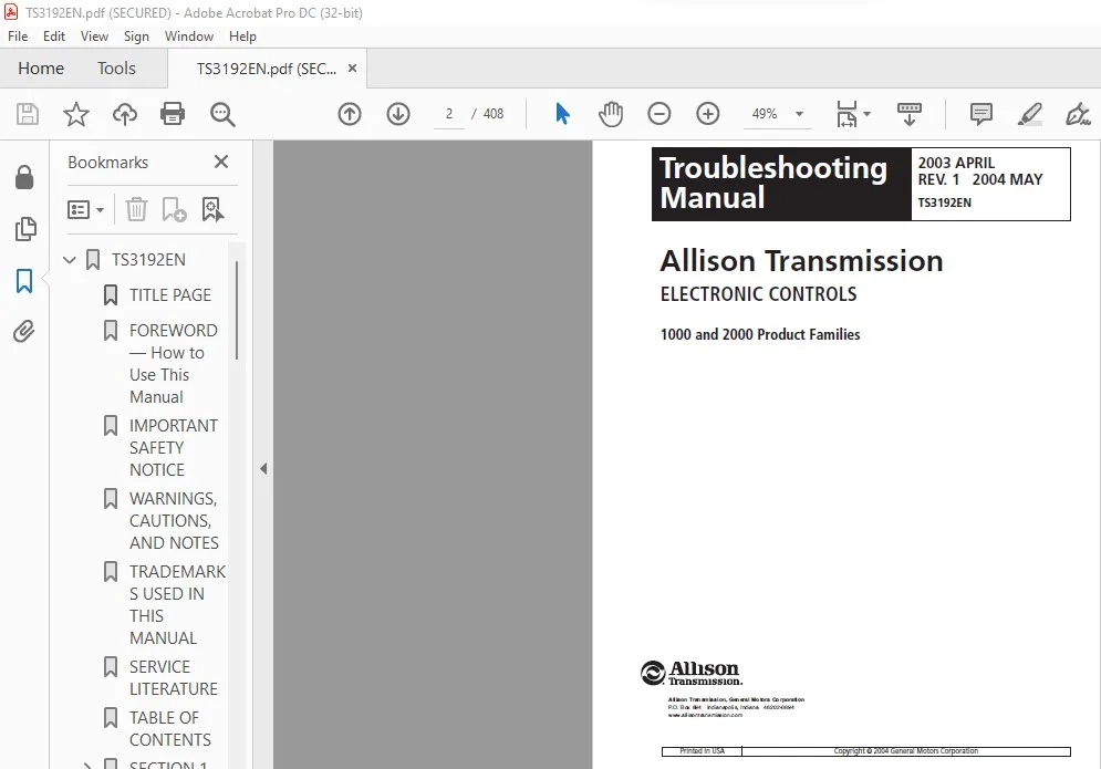
FOREWORD — How to Use This Manual
This manual provides troubleshooting information for Allison Transmission 1000 and 2000 Product
Families transmissions. Service Manual SM3191EN, Mechanics Tips MT3190EN, and Parts Catalog
PC3062EN may be used in conjunction with this manual.
This manual includes:
•Description of the electronic control system.
•Description of the electronic control system components.
•Description of diagnostic codes, system responses to faults, and troubleshooting.
•Wire, terminal, and connector repair information.
Specific instructions for using many of the available or required service tools and equipment are not
included in this manual. The service tool manufacturer will furnish instructions for using the tools or
equipment.
Additional information may be published from time to time in Service Information Letters (SIL) and will be
included in future revisions of this and other manuals. Please use these SILs to obtain up-to-date
information concerning Allison Transmission products.
This publication is revised periodically to include improvements, new models, special tools, and
procedures. A revision is indicated by a new date on the title page and rear cover. Check with your
Allison Transmission service outlet for the currently applicable publication. Additional copies of this
publication may be purchased from authorized Allison Transmission service outlets. Look in your
telephone directory under the heading of Transmissions — Truck, Tractor, etc.
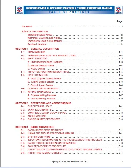
TABLE OF CONTENTS:
2003 Allison Transmission 1000 & 2000 Product Families Electronic Controls Troubleshooting Manual – PDF DOWNLOAD
TS3192EN…………………………………………………………………………………………………………. 1
TITLE PAGE……………………………………………………………………………………………………. 2
FOREWORD — How to Use This Manual……………………………………………………………………………….. 3
IMPORTANT SAFETY NOTICE………………………………………………………………………………………… 4
WARNINGS, CAUTIONS, AND NOTES…………………………………………………………………………………… 4
TRADEMARKS USED IN THIS MANUAL………………………………………………………………………………….. 5
SERVICE LITERATURE…………………………………………………………………………………………….. 5
TABLE OF CONTENTS……………………………………………………………………………………………… 6
SECTION 1— GENERAL DESCRIPTION………………………………………………………………………………….. 8
1–1. TRANSMISSION………………………………………………………………………………………….. 8
Figure 1–2. Electronic Control Components…………………………………………………………………. 9
1–2. TRANSMISSION CONTROL MODULE (TCM)……………………………………………………………………….. 10
Figure 1–3. Transmission Control Module (TCM)……………………………………………………………… 10
1–3. SHIFT SELECTOR………………………………………………………………………………………… 10
Figure 1–4. Typical Lever-Type Shift Selector……………………………………………………………… 10
Figure 1–5. NSBU Switch…………………………………………………………………………………….. 11
1–4. THROTTLE POSITION SENSOR……………………………………………………………………………….. 12
Figure 1–6. Throttle Position Sensor……………………………………………………………………… 12
1–5. SPEED SENSORS…………………………………………………………………………………………. 12
Figure 1–7. Typical Speed Sensor…………………………………………………………………………. 12
Figure 1–8. Speed Sensor Connector Orientation…………………………………………………………….. 13
1–6. CONTROL VALVE ASSEMBLY…………………………………………………………………………………. 14
Figure 1–9. Control Valve Assembly……………………………………………………………………….. 14
1–7. WIRING HARNESSES………………………………………………………………………………………. 14
Figure 1–10. Typical External Wiring Harnesses…………………………………………………………….. 15
Figure 1–11. Typical Internal Wiring Harness………………………………………………………………. 16
SECTION 2—DEFINITIONS AND ABBREVIATIONS………………………………………………………………………….. 18
2–1. CHECK TRANS LIGHT……………………………………………………………………………………… 18
2–2. SCAN TOOL INHIBITS…………………………………………………………………………………….. 18
2–3. SCAN TOOL (Allison DOC™ For PC)…………………………………………………………………………. 20
Figure 2–1. Scan Tool…………………………………………………………………………………… 20
2–4. ABBREVIATIONS…………………………………………………………………………………………. 21
2–5. RANGE INHIBIT RESPONSES………………………………………………………………………………… 23
SECTION 3—BASIC KNOWLEDGE………………………………………………………………………………………. 24
3–1. BASIC KNOWLEDGE REQUIRED……………………………………………………………………………….. 24
3–2. USING THE TROUBLESHOOTING MANUAL………………………………………………………………………… 24
3–3. SYSTEM OVERVIEW……………………………………………………………………………………….. 24
3–4. IMPORTANT INFORMATION IN THE TROUBLESHOOTING PROCESS………………………………………………………. 25
3–5. BASIC TROUBLESHOOTING INFORMATION……………………………………………………………………….. 26
Figure 3–1. Proper Allison DOC™ For PC Scan Tool Connections — J1939…………………………………………. 27
Figure 3–2. Proper Allison DOC™ For PC Scan Tool Connections — J1850…………………………………………. 28
Figure 3–3. Proper Allison DOC™ For PC Scan Tool Connections Using J1939 T-Adapter Harness (J 43890)…………….. 28
3–6. TCM REPLACEMENT PROCEDURE………………………………………………………………………………. 29
3–7. RESETTING OF TCM PARAMETERS TO SUPPORT ENGINE UPDATE………………………………………………………. 30
3–8. RESETTING TCM AUTOSELECT……………………………………………………………………………….. 30
SECTION 4—WIRE CHECK PROCEDURES…………………………………………………………………………………. 32
4–1. CHECKING OPENS, SHORTS BETWEEN WIRES, AND SHORTS-TO-GROUND…………………………………………………. 32
Figure 4–1. Checking Continuity (External Harness)…………………………………………………………. 32
Figure 4–2. Short Between Wires and to Ground (External Harness)…………………………………………….. 33
4–2. CHECKING AT TRANSMISSION CONNECTOR AND THE INTERNAL HARNESSFOR OPENS, SHORTS BETWEEN WIRES, AND SHORTS-TO-GROUND…. 33
Figure 4–3. Checking Continuity (Internal Harness)…………………………………………………………. 34
Figure 4–4. Short Between Wires and to Ground (Internal Harness)…………………………………………….. 35
SECTION 5—DIAGNOSTIC TROUBLE CODES (DTC)…………………………………………………………………………. 36
5–1. DTC MEMORY……………………………………………………………………………………………. 36
Table 5–1. DTC List…………………………………………………………………………………….. 36
5–2. FAILURE RECORDS……………………………………………………………………………………….. 36
Table 5–2. Failure Record Data…………………………………………………………………………… 36
5–3. DTC READING AND DTC CLEARING……………………………………………………………………………. 37
5–4. BEGINNING THE TROUBLESHOOTING PROCESS……………………………………………………………………. 37
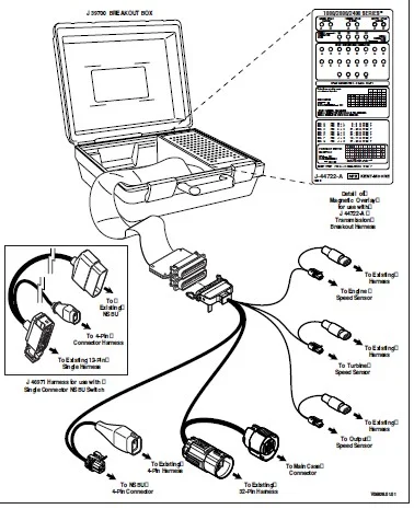
Figure 5–2. J 39700 Breakout Box And J 43799 Adapter……………………………………………………….. 39
Figure 5–3. J 39700 Breakout Box And J 44722 Adapter……………………………………………………….. 40
5–5. DIAGNOSTIC TROUBLE CODES (DTCs) DTC LIST AND DESCRIPTION INDEX……………………………………………… 41
DTC REFERENCE TABLES……………………………………………………………………………………….. 43
DTC P0122 Pedal Position Sensor Circuit Low Voltage……………………………………………………………. 51
DTC P0123 Pedal Position Sensor Circuit High Voltage…………………………………………………………… 55
DTC P0218 Transmission Fluid Over Temperature Condition………………………………………………………… 59
DTC P0561 Unrealistic Variations in Vehicle System Voltage……………………………………………………… 62
DTC P0562 System Voltage Low………………………………………………………………………………… 66
DTC P0563 System Voltage High……………………………………………………………………………….. 69
DTC P0602 TCM Not Programmed………………………………………………………………………………… 72
DTC P0606 Controller Internal Performance…………………………………………………………………….. 73
DTC P0614 Torque Control Data Mismatch — ECM/TCM………………………………………………………………. 74
DTC P0701 Transmission Control System Performance……………………………………………………………… 76
DTC P0703 Brake Switch Circuit Malfunction……………………………………………………………………. 78
DTC P0708 Transmission Range Sensor Circuit High Input…………………………………………………………. 81
DTC P0711 Transmission Fluid Temperature Sensor Circuit Performance……………………………………………… 85
DTC P0712 Transmission Fluid Temperature Sensor Circuit Low Input(High Temperature)……………………………….. 89
DTC P0713 Transmission Fluid Temperature Sensor Circuit High Input(Low Temperature)……………………………….. 93
DTC P0716 Turbine Speed Sensor Circuit Performance…………………………………………………………….. 97
DTC P0717 Turbine Speed Sensor Circuit No Signal……………………………………………………………….100
DTC P0719 Brake Switch ABS Input Low………………………………………………………………………….104
DTC P0721 Output Speed Sensor Circuit Performance………………………………………………………………106
DTC P0722 Output Speed Sensor Circuit No Signal………………………………………………………………..110
DTC P0726 Engine Speed Input Circuit Performance……………………………………………………………….114
DTC P0727 Engine Speed Input Circuit No Signal…………………………………………………………………117
DTC P0731 Incorrect 1st Gear Ratio……………………………………………………………………………120
DTC P0732 Incorrect 2nd Gear Ratio……………………………………………………………………………123
DTC P0733 Incorrect 3rd Gear Ratio……………………………………………………………………………126
DTC P0734 Incorrect 4th Gear Ratio……………………………………………………………………………129
DTC P0735 Incorrect 5th Gear Ratio……………………………………………………………………………132
DTC P0736 Incorrect Reverse Ratio…………………………………………………………………………….135
DTC P0741 Torque Converter Clutch System Stuck Off……………………………………………………………..139
DTC P0742 Torque Converter Clutch System Stuck On………………………………………………………………142
DTC P0743 (Previously P1860) Torque Converter Clutch Pulse Width Modulation (PWM)Solenoid Circuit — Electrical………..145
DTC P0746 (Previously P1720) Solenoid A Controlled Clutch Stuck Off………………………………………………150
DTC P0747 (Previously P1723) Solenoid A Controlled Clutch Stuck On……………………………………………….153
DTC P0748 Pressure Control Solenoid A Electrical……………………………………………………………….156
DTC P0763 Shift Solenoid C Electrical…………………………………………………………………………161
DTC P0768 Shift Solenoid D Electrical…………………………………………………………………………166
DTC P0773 Shift Solenoid E Electrical…………………………………………………………………………170
DTC P0776 (Previously P1721) Solenoid B Controlled Clutch Stuck Off………………………………………………174
DTC P0777 (Previously P1724) Solenoid B Controlled Clutch Stuck On……………………………………………….177
DTC P0778 Pressure Control Solenoid B Electrical……………………………………………………………….180
DTC P0840 Transmission Pressure Switch Solenoid C Circuit……………………………………………………….185
DTC P0841 Transmission Pressure Switch Solenoid C Circuit Stuck Open……………………………………………..190
DTC P0842 Transmission Pressure Switch Solenoid C Circuit Stuck Closed……………………………………………195
DTC P0843 Transmission Pressure Switch Solenoid C Circuit High…………………………………………………..200
DTC P0845 Transmission Pressure Switch Solenoid D Circuit……………………………………………………….205
DTC P0846 Transmission Pressure Switch Solenoid D Circuit Stuck Open……………………………………………..210
DTC P0847 Transmission Pressure Switch Solenoid D Circuit Stuck Closed……………………………………………215
DTC P0848 Transmission Pressure Switch Solenoid D Circuit High…………………………………………………..220
DTC P0870 (Previously P1709) Transmission Pressure Switch Solenoid E Circuit………………………………………225
DTC P0871 (Previously P1710) Transmission Pressure SwitchSolenoid E Circuit Stuck Open……………………………..230
DTC P0872 (Previously P1711) Transmission Pressure Switch Solenoid E CircuitStuck Closed……………………………235
DTC P0873 (Previously P1712) Transmission Pressure Switch Solenoid E Circuit High………………………………….240
DTC P0875 (Previously P1713) Transmission Reverse Pressure SwitchCircuit Malfunction……………………………….245
DTC P0876 (Previously P1714) Transmission Reverse Pressure Switch Circuit Stuck Open……………………………….250
DTC P0880 (Previously P1760) TCM Supply Voltage………………………………………………………………..255
DTC P1688 Unmanaged Engine Torque Delivered To TCM Signal……………………………………………………….258
DTC P1779 Engine Torque Delivered To TCM Signal………………………………………………………………..260
DTC P1891 Throttle Position Sensor (TPS) Pulse Width Modulation (PWM)Signal Low Input………………………………262
DTC P1892 Throttle Position Sensor (TPS) Pulse Width Modulation (PWM)Signal High Input……………………………..265
DTC P2771 (Previously P0836, P1875) Four-Wheel Drive Switch Circuit………………………………………………268
DTC P2773 Torque Control Request Ignored — ECM/TCM……………………………………………………………..272
DTC P2810 Solenoid G Electrical………………………………………………………………………………274
DTC U0031 (Previously U1300) J1850 (Class 2) Serial Data Communication Link Low……………………………………279
DTC U0032 (Previously U1301) J1850 (Class 2) Serial Data Communication Link High…………………………………..282
DTC U0073 (Previously U2104) CAN Bus Reset Counter Overrun………………………………………………………285
DTC U0100 (Previously U2105) CAN Bus ECM Error…………………………………………………………………288
DTC U1000–U1096 Class 2 Controller State of Health Failure………………………………………………………291
SECTION 6—INPUT AND OUTPUT FUNCTIONS……………………………………………………………………………..294
6–1. SPECIAL INPUT AND OUTPUT FUNCTIONS……………………………………………………………………….294
SECTION 7—GENERAL TROUBLESHOOTING OF PERFORMANCECOMPLAINTS………………………………………………………….296
Table 7–1. Troubleshooting Performance Complaints………………………………………………………………297
APPENDICES—INDEX……………………………………………………………………………………………….308
APPENDIX A—DIAGNOSING INTERMITTENT DTCS…………………………………………………………………………..310
APPENDIX B—MAIN PRESSURE CHECK PROCEDURE………………………………………………………………………….312
Figure B–1. Main Pressure Check Point…………………………………………………………………………312
Table B–1. Main Pressure Test Conditions………………………………………………………………………313
APPENDIX C—SOLENOID AND CLUTCH TABLE……………………………………………………………………………..314
Table C–1. Solenoid and Clutch Table — Software Levels Prior To N04………………………………………………314
Table C–1. Solenoid and Clutch Table — Software Level N04 And Later………………………………………………315
APPENDIX D—WIRE/CONNECTOR TABLES…………………………………………………………………………………316
Figure D–1. TCM Connector J2…………………………………………………………………………………317
Figure D–2. TCM Connector J1…………………………………………………………………………………318
Figure D–3. Delphi-Packard Main Transmission Connector………………………………………………………….319
Figure D–4. Speed Sensor Connector……………………………………………………………………………320
Figure D–5. TPS Connector……………………………………………………………………………………321
Figure D–6. J1939 Interface Connector…………………………………………………………………………322
Figure D–7. NSBU Switch Connectors……………………………………………………………………………323
Figure D–8. Single Connector NSBU…………………………………………………………………………….324
Figure D–9. Deutsch DDR Connector…………………………………………………………………………….325
Figure D–10. Transmission Internal Harness…………………………………………………………………….326
APPENDIX E—CONNECTOR REPAIR INFORMATION…………………………………………………………………………..328
List Of Special Tools Required To Service 1000 and 2000 Product Families Wiring Harnesses…………………………..329
Figure E–1A. Delphi-Packard Micro Pack Connector (TCM J1 and J2)……………………………………………..330
Figure E–1B. Delphi-Packard Micro Pack Connector (Main Transmission Connector)…………………………………331
1–1. DELPHI-PACKARD MICRO PACK 100W CONNECTORS(TCM J1 AND J2, MAIN TRANSMISSION CONNECTOR)………………………….332
Figure E–2. Delphi-Packard Metri-Pack 150 Series Connectors …………………………………………………335
1–2. DELPHI-PACKARD METRI-PACK 150 SERIES CONNECTORS — PULL-TO-SEAT(SPEED SENSORS)…………………………………336
Figure E–3. Delphi-Packard Metri-Pack 150 Series Connectors — Push-to-Seat (NSBU Switch)………………………..339
1–3. DELPHI-PACKARD METRI-PACK 150 SERIES CONNECTORS — PUSH-TO-SEAT(NSBU SWITCH)…………………………………..340
Figure E–4. Internal Wiring Harness……………………………………………………………………….343
1–4. INTERNAL WIRING HARNESS…………………………………………………………………………………344
Figure E–5A. Delphi-Packard WeatherPack Connectors (TPS)…………………………………………………….345
1–5. DELPHI-PACKARD WEATHERPACK CONNECTORS (TPS)……………………………………………………………….346
Figure E–5B. Terminal Crimping With Tool J 35606……………………………………………………………347
Figure E–6. Deutsch IPD/ECD Connectors (9-Way DDR)………………………………………………………….349
1–6. DEUTSCH IPD/ECD CONNECTORS (J1939 DIAGNOSTIC LINK 9-WAY DDR)………………………………………………..350
Figure E–7. Deutsch DT Series Connector (3-Way J1939 Interface)………………………………………………353
1–7. DEUTSCH DT SERIES CONNECTORS (3-WAY J1939 INTERFACE)……………………………………………………….354
1–8. REPAIR OF A BROKEN WIRE WITH IN-LINE BUTT SPLICE…………………………………………………………..356
Figure E–8. Crimper J 38125-8…………………………………………………………………………….358
1-9. List of 1000 and 2000 Product Families Connector Parts……………………………………………………..328
APPENDIX F—TPS ADJUSTMENT……………………………………………………………………………………….362
Figure F–1. Throttle Position-to-Voltage Conversion…………………………………………………………….362
Figure F–2. Throttle Position Determination Diagram…………………………………………………………….362
Table F–1. Distance (mm) of Travel Versus Volts………………………………………………………………..364
Figure F–3. Throttle Position Sensor Adjustment………………………………………………………………..365
APPENDIX G—WELDING ON VEHICLE/VEHICLE INTERFACE MODULE……………………………………………………………..366
1–1. WELDING ON VEHICLE……………………………………………………………………………………..366
APPENDIX H—HYDRAULIC SCHEMATICS………………………………………………………………………………….368
Figure H–1. Hydraulic Schematic — Neutral/Park…………………………………………………………………368
Figure H–2. Hydraulic Schematic — Reverse (Prior To Software Level N04)…………………………………………..369
Figure H–3. Hydraulic Schematic — Reverse (Software Level N04 And Later)………………………………………….370
Figure H–4. Hydraulic Schematic — 1st Range……………………………………………………………………371
Figure H–5. Hydraulic Schematic — 2nd Range……………………………………………………………………372
Figure H–6. Hydraulic Schematic — 3rd Range……………………………………………………………………373
Figure H–7. Hydraulic Schematic — 4th Range……………………………………………………………………374
Figure H–8. Hydraulic Schematic — 5th Range……………………………………………………………………375
Figure H–9. Hydraulic Schematic — Hydraulic Default Forward……………………………………………………..376
Figure H–10. Hydraulic Schematic — Hydraulic Default Reverse…………………………………………………….377
Figure J–1. 1000 and 2000 Product Families Wiring Schematic……………………………………………………..378
APPENDIX J—WIRING SCHEMATICS…………………………………………………………………………………….379
Figure J–2. J1939 Backbone (CAN Bus)………………………………………………………………………….379
APPENDIX K—RESISTANCE VS. TEMPERATURE…………………………………………………………………………….381
Figure K–1. Solenoid Resistance vs. Temperature Graph…………………………………………………………..381
Table K–1. Solenoid Resistance vs. Temperature…………………………………………………………………381
Figure K–2. Transmission Fluid Temperature Sensor Resistance vs. Sump Temperature Graph…………………………….382
Table K–2. Transmission Fluid Temperature Sensor Resistance vs. Temperature……………………………………….382
Figure K–3. Speed Sensor Resistance vs. Temperature Graph……………………………………………………….384
Table K–3. Speed Sensor Resistance vs. Temperature……………………………………………………………..384
APPENDIX L—ELECTRONIC INTERFERENCE……………………………………………………………………………….385
1–1. ELECTROMAGNETIC INTERFERENCE (EMI)/RADIO FREQUENCYINTERFERENCE (RFI)…………………………………………385
1–2. GENERAL GUIDELINES FOR RADIO EQUIPMENT INSTALLATION………………………………………………………..385
1–3. EXTERNALLY-GENERATED SPEED SENSOR SIGNALS…………………………………………………………………386
APPENDIX M — ALLISON DOC™ DIAGNOSTIC TOOL…………………………………………………………………………387
APPENDIX N—INPUT/OUTPUT FUNCTIONS………………………………………………………………………………..389
Figure N–1. Secondary Shift Schedule………………………………………………………………………….389
Figure N–2. PTO Enable………………………………………………………………………………………390
Figure N–3. Auxiliary Function Range Inhibit…………………………………………………………………..391
Figure N–4. Exhaust Brake/Preselect Request, Plus Exhaust Brake Enable (Standard)………………………………….392
Figure N–5. Exhaust Brake/Preselect Request, Plus Exhaust Brake Enable (Optional)………………………………….393
Figure N–6. Exhaust Brake/Preselect Request, Plus Engine Brake Enable (Special)……………………………………394
Figure N–7. Automatic Neutral for PTO…………………………………………………………………………395
Figure N–8. Reverse Enable…………………………………………………………………………………..396
Figure N–9. Kickdown………………………………………………………………………………………..397
Figure N–10. Refuse Packer Step Switch………………………………………………………………………..398
Figure N–11. Overdrive Disable……………………………………………………………………………….399
Figure N–12. Sump Temperature Indicator……………………………………………………………………….400
Figure N–13. Range Indicator…………………………………………………………………………………401
Figure N–14. Output Speed Indicator…………………………………………………………………………..402
APPENDIX P — FLUID CHECK PROCEDURE……………………………………………………………………………….403
Figure P–1. Fill Tube And Dipstick Requirements (Standard Oil Pan)……………………………………………….404
Figure P–2. Fill Tube And Dipstick Requirements (Shallow Oil Pan)………………………………………………..405
IMAGES PREVIEW OF THE MANUAL:
2003 ALLISON TRANSMISSION 1000 & 2000 PRODUCT FAMILIES ELECTRONIC CONTROLS TROUBLESHOOTING MANUAL – PDF DOWNLOAD:
PLEASE NOTE:
- This is the SAME manual used by the dealers to troubleshoot any faults in your vehicle. This can be yours in 2 minutes after the payment is made.
- Contact us at [email protected] should you have any queries before your purchase or that you need any other service / repair / parts operators manual.
S.V