2003 Subaru Legacy Service Manual – PDF DOWNLOAD
Original price was: $75.95.$29.95Current price is: $29.95.
2003 Subaru Legacy Service Manual – PDF DOWNLOAD
Description
2003 Subaru Legacy Service Manual – PDF DOWNLOAD
FILE DETAILS:
2003 Subaru Legacy Service Manual – PDF DOWNLOAD
Language : English
Pages : 4441
Downloadable : Yes
File Type : PDF
Size: 116 MB
IMAGES PREVIEW OF THE MANUAL:
DESCRIPTION:
2003 Subaru Legacy Service Manual – PDF DOWNLOAD
This service manual has been prepared to provide SUBARU service personnel with the necessary information and data for the correct maintenance and repair of SUBARU vehicles. This manual includes the procedures for maintenance, disassembling, reassembling, inspection and adjustment of components and diagnostics for guidance of experienced mechanics. Please peruse and utilize this manual fully to ensure complete repair work for satisfying our customers by keeping their vehicle in optimum condition. When replacement of parts during repair work is needed, be sure to use SUBARU genuine parts.
FOREWORD:
These manuals are used when performing maintenance, repair, or diagnosis of the Subaru Legacy.
Applied model: BE***** and BH***** from 2003MY.
The manuals contain the latest information at the time of publication. Changes in specifications,
methods, etc. may be made without notice.
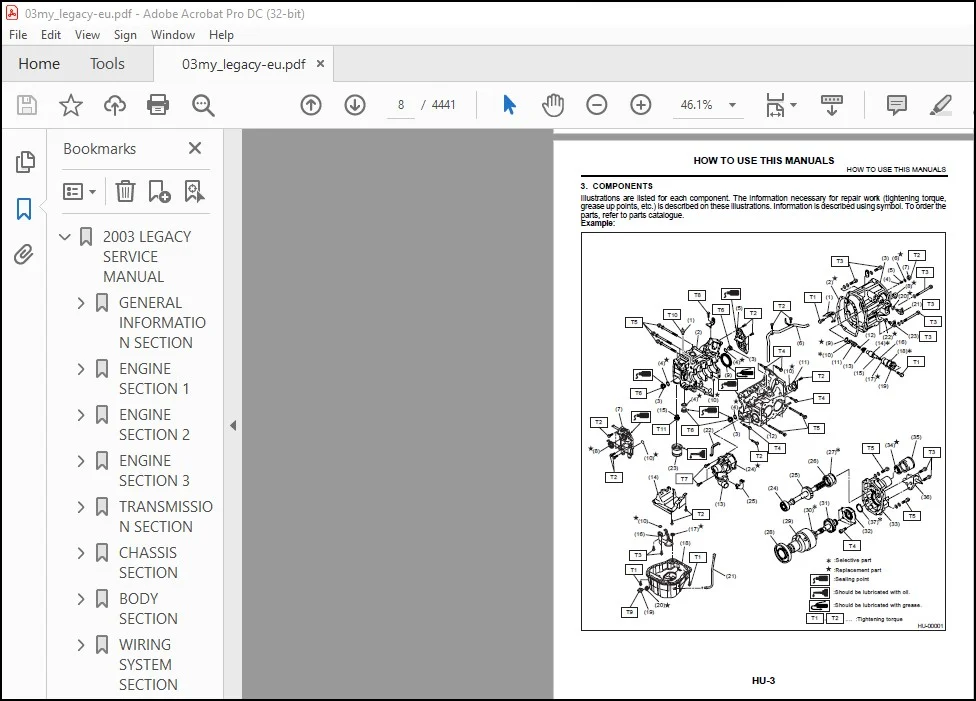
A: HOW TO USE THIS MANUALS
1. STRUCTURE
Each section consists of SCT that are broken down into SC that are divided into sections for each component.
The specification, maintenance and other information for the components are included, and
diagnosis information has also been added where necessary.
2. INDEX
The first page has an index with tabs.
TABLE OF CONTENTS:
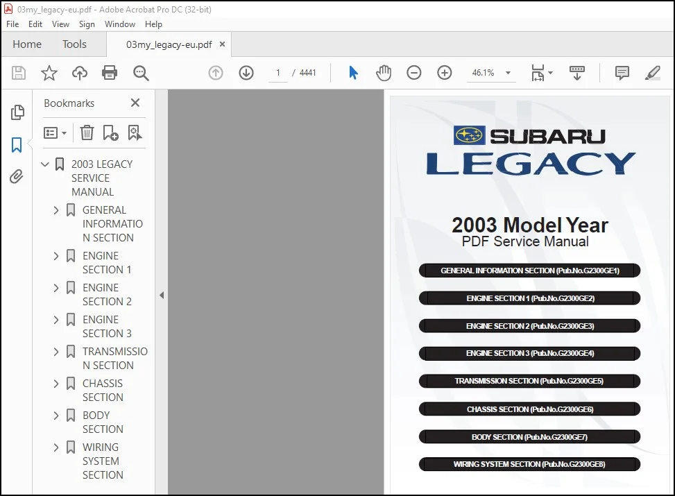
2003 Subaru Legacy Service Manual – PDF DOWNLOAD
2003 LEGACY SERVICE MANUAL 1
GENERAL INFORMATION SECTION 2
Foreword FW 4
1 Foreword 5
A: Foreword 5
How to Use This Manuals HU 6
1 How to Use This Manuals 7
A: How to Use This Manuals 7
Specifications SPC 12
1 Legacy 13
A: Dimensions 13
B: Engine 13
C: Electrical 14
D: Transmission 14
E: Steering 15
F: Suspension 15
G: Brake 15
H: Tire 15
I: Capacity 16
J: Weight 16
2 OUTBACK 21
A: Dimensions 21
B: Engine 21
C: Electrical 22
D: Transmission 22
E: Steering 23
F: Suspension 23
G: Brake 23
H: Tire 23
I: Capacity 23
J: Weight 24
Precaution PC 26
1 Precaution 27
A: Precaution 27
Note NT 28
1 Note 29
A: Note 29
Identification ID 36
1 Identification 37
A: Identification 37
Recommended Materials RM 42
1 Recommended Materials 43
A: Recommended Materials 43
Pre-delivery Inspection PI 48
1 Pre-delivery Inspection 49
A: General 49
B: PDI Procedure 50
Periodic Maintenance Services PM 60
1 General Description 61
A: General 61
2 Schedule 62
A: Maintenance Schedule 1 62
B: Maintenance Schedule 2 64
3 Engine Oil 66
A: Replacement 66
B: Inspection 67
4 Engine Oil Filter 68
A: Replacement 68
5 Spark Plugs 69
A: Replacement 69
6 Drive Belt(s) 71
A: Inspection 71
B: Replacement 72
7 Camshaft Drive Belt 74
A: Replacement 74
B: Inspection 76
8 Fuel Line 77
A: Inspection 77
9 Fuel Filter 78
A: Replacement 78
B: Inspection 78
10 Air Cleaner Element 79
A: Replacement 79
11 Cooling System 80
A: Inspection 80
12 Coolant 81
A: Replacement 81
13 Clutch System 83
A: Inspection and Adjustment 83
14 Hill-holder System 84
A: Inspection and Adjustment 84
15 Idle Mixture 85
A: Inspection and Adjustment 85
16 Transmission Oil 86
A: Replacement 86
17 ATF 87
A: Inspection 87
B: Replacement 88
18 Front & Rear Differential Oil 89
A: Replacement 89
19 Brake Line 91
A: Inspection 91
B: Checking 91
20 Brake Fluid 93
A: Replacement 93
21 Disc Brake Pads and Discs 94
A: Inspection 94
22 Parking Brake 95
A: Inspection 95
B: Adjustment 96
23 Suspension 97
A: Inspection 97
24 Wheel Bearing 99
A: Inspection 99
25 Axle Boots & Joints 100
A: Inspection 100
26 Tire Rotation 101
A: Inspection 101
27 Steering System (Power Steering) 102
A: Inspection 102
ENGINE SECTION 1 106
Fuel Injection (Fuel Systems) FU(H4SO) 108
1 General Description 109
A: Specifications 109
B: Component 111
C: Caution 120
D: Preparation Tool 120
2 Throttle Body 121
A: Removal 121
B: Installation 121
3 Intake Manifold 122
A: Removal 122
B: Installation 124
C: Disassembly 127
D: Assembly 130
E: Inspection 132
4 Engine Coolant Temperature Sensor 133
A: Removal 133
B: Installation 133
5 Crankshaft Position Sensor 134
A: Removal 134
B: Installation 134
6 Camshaft Position Sensor 135
A: Removal 135
B: Installation 135
7 Knock Sensor 136
A: Removal 136
B: Installation 136
8 Throttle Position Sensor 137
A: Removal 137
B: Installation 137
C: Adjustment 137
9 Pressure Sensor 139
A: Removal 139
B: Installation 139
10 Intake Air Temperature Sensor 140
A: Removal 140
B: Installation 140
11 Idle Air Control Solenoid Valve 141
A: Removal 141
B: Installation 141
12 EGR Valve 142
A: Removal 142
B: Installation 142
13 Fuel Injector 143
A: Removal 143
B: Installation 146
14 Front Oxygen (A/F) Sensor 148
A: Removal 148
B: Installation 148
15 Rear Oxygen Sensor 150
A: Removal 150
B: Installation 150
16 Engine Control Module 152
A: Removal 152
B: Installation 152
17 Main Relay 153
A: Removal 153
B: INstallation 153
18 Fuel Pump Relay 154
A: Removal 154
B: Installation 154
19 Fuel 155
A: Operation 155
20 Fuel Tank 158
A: Removal 158
B: Installation 160
C: Inspection 164
21 Fuel Filler Pipe 165
A: Removal 165
B: Installation 166
22 Fuel Pump 169
A: Removal 169
B: Installation 170
C: Disassembly 170
D: Assembly 170
E: Inspection 170
23 Fuel Level Sensor 171
A: Removal 171
B: Installation 171
24 Fuel Sub Level Sensor 172
A: Removal 172
B: Installation 173
25 Fuel Filter 174
A: Removal 174
B: Installation 174
C: Inspection 174
26 Fuel Cut Valve 175
A: Removal 175
B: Installation 175
27 Fuel Damper Valve 176
A: Removal 176
B: Installation 176
28 Fuel Delivery, Return and Evaporation Lines 177
A: Removal 177
B: Installation 178
C: Inspection 179
29 Fuel System Trouble in General 180
A: Inspection 180
Emission Control (Aux Emission Control Devices) EC(H4SO) 182
1 General Description 183
A: Caution 183
2 Front Catalytic Converter 184
A: Removal 184
B: Installation 184
C: Inspection 184
3 Rear Catalytic Converter 185
A: Removal 185
B: Installation 185
C: Inspection 185
4 EGR Valve 186
A: Removal 186
B: Installation 186
5 Canister 187
A: Removal 187
B: Installation 187
C: Inspection 187
6 Purge Control Solenoid Valve 188
A: Removal 188
B: Installation 188
C: Inspection 188
7 Two-way Valve 189
A: Removal 189
B: Installation 189
C: Inspection 189
Intake (Induction) IN(H4SO) 190
1 General Description 191
A: Component 191
B: Caution 193
2 Air Cleaner 194
A: Removal 194
B: Installation 194
C: Inspection 194
3 Air Cleaner Case 195
A: Removal 195
B: Installation 195
C: inspection 195
4 Air Intake Duct 196
A: Removal 196
B: Installation 196
C: Inspection 196
5 Resonator Chamber 197
A: Removal 197
B: Installation 197
C: Inspection 197
Mechanical ME(H4SO) 198
1 General Description 199
A: Specifications 199
B: Component 203
C: Caution 212
D: Preparation Tool 212
E: Procedure 219
2 Compression 220
A: Inspection 220
3 Idle Speed 221
A: Inspection 221
4 Ignition Timing 222
A: Inspection 222
5 Intake Manifold Vacuum 223
A: Inspection 223
6 Engine Oil Pressure 224
A: Inspection 224
7 Fuel Pressure 225
A: Inspection 225
8 Valve Clearance 226
A: Inspection 226
B: Adjustment 227
9 Engine Assembly 229
A: Removal 229
B: Installation 233
C: Inspection 235
10 Engine Mounting 236
A: Removal 236
B: Installation 236
C: Inspection 236
11 Preparation for Overhaul 237
A: Procedure 237
12 V-belt 238
A: Removal 238
B: Installation 239
C: Inspection 239
13 Crankshaft Pulley 240
A: Removal 240
B: Installation 240
C: Inspection 241
14 Belt Cover 242
A: Removal 242
B: Installation 242
C: Inspection 242
15 Timing Belt Assembly 243
A: Removal 243
B: Installation 244
C: Inspection 247
16 Camshaft Sprocket 248
A: Removal 248
B: Installation 248
C: Inspection 249
17 Crankshaft Sprocket 250
A: Removal 250
B: Installation 250
C: Inspection 250
18 Valve Rocker Assembly 251
A: Removal 251
B: Installation 251
C: Disassembly 251
D: Assembly 252
E: Inspection 252
19 Camshaft 253
A: Removal 253
B: Installation 254
C: Inspection 256
20 Cylinder Head Assembly 257
A: Removal 257
B: Installation 257
C: Disassembly 258
D: Assembly 258
E: Inspection 259
F: Adjustment 260
21 Cylinder Block 264
A: Removal 264
B: Installation 269
C: Disassembly 277
D: Assembly 278
E: Inspection 278
22 Engine Trouble in General 286
A: Inspection 286
23 Engine Noise 291
A: Inspection 291
Exhaust EX(H4SO) 292
1 General Description 293
A: COMPONENT 293
B: CAUTION 295
2 Front Exhaust Pipe 296
A: REMOVAL 296
B: INSTALLATION 297
C: INSPECTION 298
3 Center Exhaust Pipe 299
A: REMOVAL 299
B: INSTALLATION 299
C: INSPECTION 299
4 Rear Exhaust Pipe 300
A: REMOVAL 300
B: INSTALLATION 300
C: INSPECTION 300
5 Muffler 301
A: REMOVAL 301
B: INSTALLATION 301
C: INSPECTION 301
Cooling CO(H4SO) 302
1 General Description 303
A: Specifications 303
B: Component 304
C: Caution 306
D: Preparation Tool 306
2 Radiator Main Fan System 307
A: Schematic 307
B: Inspection 308
3 Radiator Sub Fan System 311
A: Schematic 311
B: Inspection 312
4 Engine Coolant 315
A: Replacement 315
B: Inspection 316
5 Water Pump 317
A: Removal 317
B: Installation 319
C: Inspection 321
6 Thermostat 322
A: Removal 322
B: Installation 322
C: Inspection 322
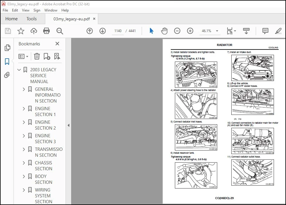
7 Radiator 324
A: Removal 324
B: Installation 325
C: Inspection 327
8 Radiator Cap 328
A: Inspection 328
9 Radiator Main Fan and Fan Motor 329
A: Removal 329
B: Installation 330
C: Disassembly 330
D: Assembly 330
E: Inspection 330
10 Radiator Sub Fan and Fan Motor 331
A: Removal 331
B: Installation 331
C: Disassembly 331
D: Assembly 332
E: Inspection 332
11 Reservoir Tank 333
A: Removal 333
B: Installation 333
C: Inspection 333
12 Engine Cooling System Trouble in General 334
A: Inspection 334
Lubrication LU(H4SO) 336
1 General Description 337
A: Specifications 337
B: Component 338
C: Caution 339
D: Preparation Tool 340
2 Oil Pressure System 341
A: Schematic 341
B: Inspection 342
3 Engine Oil 343
A: Inspection 343
B: Replacement 343
4 Oil Pump 345
A: Removal 345
B: Installation 346
C: Disassembly 346
D: Assembly 347
E: Inspection 347
5 Oil Pan and Strainer 349
A: Removal 349
B: Installation 350
C: Inspection 351
6 Oil Pressure Switch 352
A: Removal 352
B: Installation 352
C: Inspection 352
7 Engine Oil Filter 353
A: Removal 353
B: Installation 353
C: Inspection 353
8 Engine Lubrication System Trouble in General 354
A: Inspection 354
Speed Control Systems SP(H4SO) 356
1 General Description 357
A: Specification 357
B: Component 357
C: CAUTION 359
2 Accelerator Pedal 360
A: Removal 360
B: Installation 361
C: Disassembly 362
D: Assembly 362
E: Inspection 363
F: Adjustment 363
3 Accelerator Control Cable 365
A: Removal 365
B: Installation 365
C: Inspection 365
Ignition IG(H4SO) 366
1 General Description 367
A: Specifications 367
B: Component 368
C: Caution 369
2 Spark Plug 370
A: Removal 370
B: Installation 371
C: Inspection 371
D: Cleaning 372
E: Adjustment 372
3 Ignition Coil and Ignitor Assembly 373
A: Removal 373
B: Installation 373
C: Inspection 373
4 Spark Plug Cord 375
A: Inspection 375
Starting/Charging Systems SC(H4SO) 376
1 General Description 377
A: Specifications 377
B: Component 378
C: Caution 380
2 Starter 381
A: Removal 381
B: Installation 381
C: Disassembly 382
D: Assembly 384
E: Inspection 385
3 Generator 389
A: REMOVAL 389
B: INSTALLATION 389
C: DISASSEMBLY 389
D: ASSEMBLY 392
E: INSPECTION 393
4 Battery 395
A: REMOVAL 395
B: INSTALLATION 395
C: INSPECTION 395
D: MEASUREMENT 396
Engine (Diagnostics) EN(H4SO) 398
1 Basic Diagnostic Procedure 399
A: Procedure 399
2 Check List for Interview 401
A: Check 401
3 General Description 403
A: Caution 403
B: Inspection 404
C: Note 404
D: Preparation Tool 405
4 Electrical Components Location 407
A: Location 407
5 Engine Control Module (ECM) I/O Signal 421
A: Electrical Specification 421
6 Engine Condition Data 424
A: Electrical Specification 424
7 Transmission Control Module (TCM) I/O Signal 425
A: Electrical Specification 425
8 Data Link Connector 426
A: NOTE 426
9 OBD-II General Scan Tool 427
A: Operation 427
10 Subaru Select Monitor 429
A: Operation 429
11 Read Diagnostic Trouble Code 436
A: Operation 436
12 Inspection Mode 437
A: Operation 437
13 Drive Cycle 442
A: Operation 442
14 Clear Memory Mode 444
A: Operation 444
15 Compulsory Valve Operation Check Mode 445
A: Operation 445
16 Engine Malfunction Indicator Lamp (MI) 447
A: Procedure 447
B: Activation of Check Engine Malfunction Indicator Lamp (MI) 447
C: Check Engine Malfunction Indicator Lamp (MI) Does Not Come On 449
D: Check Engine Malfunction Indicator Lamp (MI) Does Not Go Off 453
E: Check Engine Malfunction Indicator Lamp (MI) Does Not Blink at a Cycle of 3 Hz 455
F: Check Engine Malfunction Indicator Lamp (MI) Remains Blinking at a Cycle of 3 Hz 457
17 Diagnostics for Engine Starting Failure 459
A: Procedure 459
B: Starter Motor Circuit 461
C: Control Module Power Supply and Ground Line 465
D: Ignition Control System 469
E: Fuel Pump Circuit 473
F: Fuel Injector Circuit 477
18 List of Diagnostic Trouble Code (DTC) 480
A: List 480
19 Diagnostic Procedure with Diagnostic Trouble Code (DTC) 487
A: DTC P0030 — HO2S Heater Control Circuit (Bank 1 Sensor 1) — 487
B: DTC P0031 — HO2S Heater Control Circuit Low (Bank 1 Sensor 1) — 489
C: DTC P0032 — HO2S Heater Control Circuit High (Bank 1 Sensor 1) — 493
D: DTC P0037 — HO2S Heater Control Circuit Low (Bank 1 Sensor 2) — 495
E: DTC P0038 — HO2S Heater Control Circuit High (Bank 1 Sensor 2) — 499
F: DTC P0068 — Manifold Absolute Pressure/Barometric Pressure Circuit Range/Performance — 501
G: DTC P0107 — Manifold Absolute Pressure/Barometric Pressure Circuit Low Input — 503
H: DTC P0108 — Manifold absolute pressure/barometric pressure circuit high input — 507
I: DTC P0111 — Intake air temperature circuit range/performance — 511
J: DTC P0112 — Intake air temperature circuit low input — 513
K: DTC P0113 — Intake air temperature circuit high input — 515
L: DTC P0117 — Engine coolant temperature circuit low input — 519
M: DTC P0118 — Engine coolant temperature circuit high input — 521
N: DTC P0121 — Throttle/pedal position sensor/switch “A” circuit range/performance — 525
O: DTC P0122 — Throttle/pedal position sensor/switch “A” circuit low input — 527
P: DTC P0123 — Throttle/pedal position sensor/switch “A” circuit high input — 531
Q: DTC P0125 — Insufficient coolant temperature for closed loop fuel control — 533
R: DTC P0129 — Barometric pressure too low — 535
S: DTC P0130 — O2 sensor circuit (Bank 1 Sensor 1) — 537
T: DTC P0131 — O2 sensor circuit low voltage (Bank 1 Sensor 1) — 541
U: DTC P0132 — O2 sensor circuit high voltage (Bank 1 Sensor 1) — 543
V: DTC P0133 — O2 sensor circuit slow response (Bank 1 Sensor 1) — 545
W: DTC P0134 — O2 sensor circuit no activity detected (Bank 1 Sensor 1) — 547
X: DTC P0137 — O2 sensor circuit low voltage (Bank 1 Sensor 2) — 549
Y: DTC P0138 — O2 sensor circuit high voltage (Bank 1 Sensor 2) — 553
Z: DTC P0139 — O2 sensor circuit slow response (Bank 1 Sensor 2) — 557
AA: DTC P0171 — System too lean (Bank 1) — 559
AB: DTC P0172 — System too rich (Bank 1) — 561
AC: DTC P0301 — Cylinder 1 Misfire Detected — 564
AD: DTC P0302 — Cylinder 2 Misfire Detected — 564
AE: DTC P0303 — Cylinder 3 Misfire Detected — 564
AF: DTC P0304 — Cylinder 4 Misfire Detected — 565
AG: DTC P0327 — Knock sensor 1 circuit low input (Bank 1 or Single Sensor) — 573
AH: DTC P0328 — Knock sensor 1 circuit high input (Bank 1 or Single Sensor) — 575
AI: DTC P0335 — Crankshaft position sensor “A” circuit — 577
AJ: DTC P0336 — Crankshaft position sensor “A” circuit range/ performance — 579
AK: DTC P0340 — Camshaft position sensor “A” circuit (Bank 1 or Single Sensor) — 581
AL: DTC P0341 — Camshaft position sensor “A” circuit range/performance (Bank 1 or Single Sensor) — 583
AM: DTC P0400 — Exhaust Gas Recirculation Flow — 587
AN: DTC P0420 — Catalyst system efficiency below threshold (Bank 1) — 591
AO: DTC P0458 — Evaporative emission control system purge control valve circuit low — 593
AP: DTC P0459 — Evaporative emission control system purge control valve circuit high — 597
AQ: DTC P0461 — Fuel Level Sensor Circuit Range/Performance — 601
AR: DTC P0462 — Fuel level sensor circuit low input — 603
AS: DTC P0463 — Fuel level sensor circuit high input — 607
AT: DTC P0464 — Fuel level sensor circuit intermittent— 611
AU: DTC P0483 — Cooling fan rationality check — 613
AV: DTC P0502 — Vehicle speed sensor circuit low input — 617
AW: DTC P0503 — Vehicle speed sensor intermittent/erratic/high — 619
AX: DTC P0506 — Idle control system RPM lower than expected — 623
AY: DTC P0507 — Idle Control system RPM higher than expected — 625
AZ: DTC P0512 — Starter request circuit — 627
BA: DTC P0519 — Idle air control circuit system performance — 629
BB: DTC P0565 — Cruise control on signal — 631
BC: DTC P0604 — Internal control module random access memory (RAM) error — 633
BD: DTC P0691 — Cooling fan 1 control circuit low — 635
BE: DTC P0692 — Cooling fan 1 control circuit high — 639
BF: DTC P0703 — Torque converter/brake switch “B” circuit — 643
BG: DTC P0731 — Gear 1 Incorrect Ratio — 645
BH: DTC P0732 — Gear 2 Incorrect Ratio — 645
BI: DTC P0733 — Gear 3 Incorrect Ratio — 645
BJ: DTC P0734 — Gear 4 Incorrect Ratio — 647
BK: DTC P0741 — Torque converter clutch circuit performance or stuck off — 649
BL: DTC P0851 — Neutral switch input circuit low (AT model) — 651
BM: DTC P0851 — Neutral switch input circuit low (MT model) — 653
BN: DTC P0852 — Neutral switch input circuit high (AT model) — 655
BO: DTC P0852 — Neutral switch input circuit high (MT model) — 659
BP: DTC P0864 — TCM Communication circuit range/performance — 663
BQ: DTC P0865 — TCM Communication circuit low — 665
BR: DTC P0866 — TCM Communication circuit high — 667
BS: DTC P1110 — Atmospheric pressure sensor circuit malfunction (low input) — 669
BT: DTC P1111 — Atmospheric pressure sensor circuit malfunction (high input) — 670
BU: DTC P1134 — A/F sensor micro-computer problem — 671
BV: DTC P1137 — O2 sensor circuit (Bank 1 Sensor 1) — 673
BW: DTC P1492 — EGR solenoid valve signal #1 circuit malfunction (low input) — 676
BX: DTC P1493 — EGR solenoid valve signal #1 circuit malfunction (high input) — 676
BY: DTC P1494 — EGR solenoid valve signal #2 circuit malfunction (low input) — 676
BZ: DTC P1495 — EGR solenoid valve signal #2 circuit malfunction (high input) — 676
CA: DTC P1496 — EGR solenoid valve signal #3 circuit malfunction (low input)— 676
CB: DTC P1497 — EGR solenoid valve signal #3 circuit malfunction (high input) — 676
CC: DTC P1498 — EGR solenoid valve signal #4 circuit malfunction (low input) — 677
CD: DTC P1499 — EGR solenoid valve signal #4 circuit malfunction (high input) — 679
CE: DTC P1510 — ISC solenoid valve signal #1 circuit malfunction (low input) — 681
CF: DTC P1511 — ISC solenoid valve signal #1 circuit malfunction (high input) — 681
CG: DTC P1512 — ISC solenoid valve signal #2 circuit malfunction (low input) — 681
CH: DTC P1513 — ISC solenoid valve signal #2 circuit malfunction (high input) — 681
CI: DTC P1514 — ISC solenoid valve signal #3 circuit malfunction (low input) — 681
CJ: DTC P1515 — ISC solenoid valve signal #3 circuit malfunction (high input) — 681
CK: DTC P1516 — ISC solenoid valve signal #4 circuit malfunction (low input) — 683
CL: DTC P1517 — ISC solenoid valve signal #4 circuit malfunction (high input) — 685
CM: DTC P1518 — Starter switch circuit low input — 687
CN: DTC P1560 — Back-up voltage circuit malfunction — 691
CO: DTC P1698 — Engine torque control cut signal circuit malfunction (low input) — 693
CP: DTC P1699 — Engine torque control cut signal circuit malfunction (high input) — 695
CQ: DTC P1711 — Engine torque control signal #1 circuit malfunction — 697
CR: DTC P1712 — Engine torque control signal #2 circuit malfunction — 699
20 General Diagnostic Table 701
A: Inspection 701
Fuel Injection (Fuel Systems) FU(H4SOw/oOBD) 704
1 General Description 705
A: Specifications 705
B: Component 707
C: Caution 715
D: Preparation Tool 715
2 Throttle Body 716
A: Removal 716
B: Installation 716
3 Intake Manifold 717
A: Removal 717
B: Installation 719
C: Disassembly 722
D: Assembly 725
E: Inspection 728
4 Engine Coolant Temperature Sensor 729
A: Removal 729
B: Installation 729
5 Crankshaft Position Sensor 730
A: Removal 730
B: Installation 730
6 Camshaft Position Sensor 731
A: Removal 731
B: Installation 731
7 Knock Sensor 732
A: Removal 732
B: Installation 732
8 Throttle Position Sensor 733
A: Removal 733
B: Installation 733
C: Adjustment 733
9 Intake Air Temperature and Pressure Sensor 735
A: Removal 735
B: Installation 735
10 Idle Air Control Solenoid Valve 736
A: Removal 736
B: Installation 736
11 Fuel Injector 737
A: Removal 737
B: Installation 740
12 Oxygen Sensor 743
A: Removal 743
B: Installation 743
13 Engine Control Module 745
A: Removal 745
B: Installation 745
14 Main Relay 746
A: Removal 746
B: Installation 746
15 Fuel Pump Relay 747
A: Removal 747
B: Installation 747
16 Fuel 748
A: Operation 748
17 Fuel Tank 751
A: Removal 751
B: Installation 754
C: Inspection 757
18 Fuel Filler Pipe 758
A: Removal 758
B: Installation 759
19 Fuel Pump 762
A: Removal 762
B: Installation 763
C: Disassembly 763
D: Assembly 763
E: Inspection 763
20 Fuel Level Sensor 764
A: Removal 764
B: Installation 764
21 Fuel Sub Level Sensor 765
A: Removal 765
B: Installation 766
22 Fuel Filter 767
A: Removal 767
B: Installation 767
C: Inspection 767
23 Fuel Cut Valve 768
A: Removal 768
B: Installation 768
24 Fuel Damper Valve 769
A: Removal 769
B: Installation 769
25 Fuel Delivery, Return and Evaporation Lines 770
A: Removal 770
B: Installation 771
C: Inspection 772
26 Fuel System Trouble in General 773
A: Inspection 773
Emission Control (AUX Emission Control Devices) EC(H4SOw/oOBD) 774
1 General Description 775
A: Caution 775
2 Front Catalytic Converter 776
A: Removal 776
B: Installation 777
C: Inspection 778
3 Rear Catalytic Converter 779
A: Removal 779
B: Installation 779
C: Inspection 779
4 Canister 780
A: Removal 780
B: Installation 780
C: Inspection 780
5 Purge Control Solenoid Valve 781
A: Removal 781
B: Installation 781
C: Inspection 781
6 Two-way Valve 782
A: Removal 782
B: Installation 782
C: Inspection 782
Intake (Induction) IN(H4SOw/oOBD) 784
1 General Description 785
A: Specifications 785
Mechanical ME(H4SOw/oOBD) 786
1 General Description 787
A: Specifications 787
Exhaust EX(H4SOw/oOBD) 788
1 General Description 789
A: Component 789
B: Caution 795
2 Front Exhaust Pipe 796
A: Removal 796
B: Installation 797
C: Inspection 798
3 Center Exhaust Pipe 799
A: Removal 799
B: Installation 799
C: Inspection 799
4 Rear Exhaust Pipe 800
A: Removal 800
B: Installation 800
C: Inspection 800
5 Muffler 801
A: Removal 801
B: Installation 801
C: Inspectioin 801
Cooling CO(H4SOw/oOBD) 802
1 General Description 803
A: Specifications 803
Lubrication LU(H4SOw/oOBD) 804
1 General Description 805
A: Specifications 805
Speed Control Systems SP(H4SOw/oOBD) 806
1 General Description 807
A: Specification 807
Ignition IG(H4SOw/oOBD) 808
1 General Description 809
A: Specifications 809
B: Component 810
C: Caution 811
2 Spark Plug 812
A: Removal 812
B: Installation 813
C: Inspection 813
D: Cleaning 814
E: Adjustment 814
3 Ignition Coil and Ignitor Assembly 815
A: Removal 815
B: Installation 815
C: Inspection 815
4 Spark Plug Cord 817
A: Inspection 817
Starting/Charging Systems SC(H4SOw/oOBD) 818
1 General Description 819
A: Specifications 819
Engine (Diagnostics) EN(H4SOw/oOBD) 820
1 Basic Diagnostic Procedure 821
A: Procedure 821
2 Check List for Interview 823
A: Check 823
3 General Description 825
A: Caution 825
B: Inspection 826
C: Note 826
D: Preparation Tool 827
4 Electrical Components Location 828
A: Location 828
5 Engine Control Module (ECM) I/O Signal 837
A: Electrical Specification 837
6 Subaru Select Monitor 840
A: Operation 840
7 Read Diagnostic Trouble Code (DTC) 843
A: Operation 843
8 Inspection Mode 845
A: Operation 845
9 Clear Memory Mode 847
A: Operation 847
10 Compulsory Valve Operation Check Mode 848
A: Operation 848
11 Engine Malfunction Indicator Lamp (MIL) 849
A: Procedure 849
B: Activation of Check Engine Malfunction Indicator Lamp (MIL) 849
C: Check Engine Malfunction Indicator Lamp (MIL) Does Not Come On 850
D: Check Engine Malfunction Indicator Lamp (MIL) Does Not Go Off 853
E: CHECK ENGINE MALFUNCTION INDICATOR LAMP (MIL) DOES NOT BLINK AT A CYCLE OF 3 Hz 854
F: CHECK ENGINE MALFUNCTION INDICATOR LAMP (MIL) REMAINS BLINKING AT A CYCLE OF 3 Hz 856
12 Diagnostics for Engine Starting Failure 858
A: Procedure 858
B: Starter Motor Circuit 859
C: Control Module Power Supply and Ground Line 862
D: Ignition Control System 865
E: Fuel Pump Circuit 869
F: Fuel Injector Circuit 872
13 List of Diagnostic Trouble Code (DTC) 876
A: List 876
14 Diagnostic Procedure with Diagnostic Trouble Code (DTC) 878
A: DTC 11 Crankshaft Position Sensor 878
B: DTC 12 Starter Switch 881
C: DTC 13 Camshaft Position Sensor 883
D: DTC 21 Engine Coolant Temperature Sensor 886
E: DTC 22 Knock Sensor 890
F: DTC 24 Idle Air Control Solenoid Valve 892
G: DTC 26 Intake Air Temperature Sensor 895
H: DTC 31 Throttle Position Sensor 898
I: DTC 32 Oxygen Sensor 900
J: DTC 33 Vehicle Speed Signal 903
K: DTC 35 Purge Control Solenoid Valve 905
L: DTC 38 Torque Control Signal 908
M: DTC 45 Pressure Sensor 910
N: DTC 46 CO Resistor (General Spec Vehicles) 912
O: DTC 51 Neutral Position Switch (MT Vehicle) 914
P: DTC 51 Park/Neutral Position Switch (AT Vehicle) 917
Q: DTC 85 Charge System 919
15 General Diagnostic Table 921
A: Inspection 921
ENGINE SECTION 2 924
Fuel Injection (Fuel Systems) FU(H6DO) 926
1 General Description 927
A: Specifications 927
B: Component 929
C: Caution 940
D: Preparation Tool 940
2 Throttle Body 941
A: Removal 941
B: Installation 941
3 Intake Manifold 942
A: Removal 942
B: Installation 945
C: Disassembly 949
D: Assembly 950
4 Engine Coolant Temperature Sensor 954
A: Removal 954
B: Installation 954
5 Crankshaft Position Sensor 955
A: Removal 955
B: Installation 955
6 Camshaft Position Sensor 956
A: Removal 956
B: Installation 956
7 Knock Sensor 957
A: Removal 957
B: Installation 957
8 Throttle Position Sensor 958
A: Removal 958
B: Installation 958
9 Intake Manifold Pressure Sensor 959
A: Removal 959
B: Installation 959
10 Intake Air Temperature Sensor 960
A: Removal 960
B: Installation 960
11 Idle Air Control Solenoid Valve 961
A: Removal 961
B: Installation 961
12 Induction Valve 962
A: Removal 962
B: Installation 962
13 Induction Valve Control Solenoid 963
A: Removal 963
B: Installation 963
14 Fuel Injector 964
A: Removal 964
B: Installation 966
15 Front Oxygen (A/F) Sensor 968
A: Removal 968
B: Installation 969
16 Rear Oxygen Sensor 970
A: Removal 970
B: Installation 970
17 Engine Control Module 971
A: Removal 971
B: Installation 971
18 Main Relay 972
A: Removal 972
B: Installation 972
19 Fuel Pump Relay 973
A: Removal 973
B: Installation 973
20 Fuel Pump Controller 974
A: Removal 974
B: Installation 974
21 Fuel 975
A: Operation 975
22 Fuel Tank 978
A: Removal 978
B: Installation 981
C: Inspection 985
23 Fuel Filler Pipe 986
A: Removal 986
B: Installation 987
24 Fuel Pump 990
A: Removal 990
B: Installation 991
C: Disassembly 991
D: Assembly 991
E: Inspection 991
25 Fuel Level Sensor 992
A: Removal 992
B: Installation 992
26 Fuel Sub Level Sensor 993
A: Removal 993
B: Installation 994
27 Fuel Filter 995
A: Removal 995
B: Installation 995
C: Inspection 995
28 Fuel Cut Valve 996
A: Removal 996
B: Installation 996
29 Fuel Damper Valve 997
A: Removal 997
B: Installation 997
30 Fuel Delivery, Return and Evaporation Lines 998
A: Removal 998
B: Installation 999
C: Inspection 1000
31 Fuel System Trouble in General 1001
A: Inspection 1001
Emission Control (Aux Emission Control Devices) EC(H6DO) 1002
1 General Description 1003
A: Caution 1003
2 Front Catalytic Converter 1004
A: Removal 1004
B: Installation 1005
C: Inspection 1006
3 Rear Catalytic Converter 1007
A: Removal 1007
B: Installation 1007
C: Inspection 1007
4 Canister 1008
A: Removal 1008
B: Installation 1008
C: Inspection 1008
5 Purge Control Solenoid Valve 1009
A: Removal 1009
B: Installation 1010
C: Inspection 1010
6 EGR Valve 1011
A: Removal 1011
B: Installation 1011
C: Inspection 1012
7 Two-way valve 1013
A: Removal 1013
B: Installation 1013
C: Inspection 1013
Intake (Induction) IN(H6DO) 1014
1 General Description 1015
A: Component 1015
B: Caution 1017
2 Air Cleaner 1018
A: Removal 1018
B: Installation 1018
C: Inspection 1018
3 Air Intake Chamber 1019
A: Removal 1019
B: Installation 1019
C: inspection 1019
4 Air Intake Duct 1020
A: Removal 1020
B: Installation 1020
C: Inspection 1020
5 Resonator Chamber 1021
A: Removal 1021
B: Installation 1021
C: Inspection 1021
Mechanical ME(H6DO) 1022
1 General Description 1023
A: Specifications 1023
B: Component 1026
C: Caution 1034
D: Preparation Tool 1035
E: Procedure 1039
2 Compression 1040
A: Inspection 1040
3 Idle Speed 1041
A: Inspection 1041
4 Ignition Timing 1042
A: Inspection 1042
5 Valve Clearance 1043
A: Inspection 1043
B: Adjustment 1046
6 V-belt 1049
A: Removal 1049
B: Installation 1049
C: Inspection 1049
7 Engine Assembly 1050
A: Removal 1050
B: Installation 1053
C: Inspection 1056
8 Engine Mounting 1057
A: Removal 1057
B: Installation 1057
C: Inspection 1057
9 Preparation for Overhaul 1058
A: Removal 1058
10 Crankshaft Pulley 1059
A: Removal 1059
B: Installation 1059
C: Inspection 1059
11 Front Chain Cover 1060
A: Removal 1060
B: Installation 1060
C: Inspection 1061
12 Timing Chain Assembly 1062
A: Removal 1062
B: Installation 1063
13 Camshaft Sprocket 1067
A: Removal 1067
B: Installation 1067
C: Inspection 1067
14 Crankshaft Sprocket 1068
A: Removal 1068
B: Installation 1068
C: Inspection 1068
15 Rear Chain Cover 1069
A: Removal 1069
B: Installation 1069
16 Camshaft 1071
A: Removal 1071
B: Installation 1071
C: Inspection 1073
17 Cylinder Head Assembly 1075
A: Removal 1075
B: Installation 1075
C: Disassembly 1076
D: Assembly 1076
E: Inspection 1077
F: Adjustment 1078
18 Cylinder Block 1081
A: Removal 1081
B: Installation 1083
C: Disassembly 1087
D: Assembly 1088
E: Inspection 1088
19 Engine Trouble in General 1095
A: Inspection 1095
20 Engine Noise 1100
A: Inspection 1100
Exhaust EX(H6DO) 1102
1 General Description 1103
A: COMPONENT 1103
B: CAUTION 1105
2 Front Exhaust Pipe 1106
A: REMOVAL 1106
B: INSTALLATION 1107
C: INSPECTION 1108
3 Rear Exhaust Pipe 1109
A: REMOVAL 1109
B: INSTALLATION 1109
C: INSPECTION 1109
4 Muffler 1110
A: REMOVAL 1110
B: INSTALLATION 1110
C: INSPECTION 1110
Cooling CO(H6DO) 1112
1 General Description 1113
A: Specifications 1113
B: Component 1114
C: Caution 1116
D: Preparation Tool 1116
2 Radiator Main Fan System 1117
A: Schematic 1117
B: Inspection 1118
3 Radiator Sub Fan System 1125
A: Schematic 1125
B: Inspection 1126
4 Engine Coolant 1133
A: Replacement 1133
B: Inspection 1134
5 Water Pump 1135
A: Removal 1135
B: Installation 1135
C: Inspection 1135
6 Thermostat 1136
A: Removal 1136
B: Installation 1136
C: Inspection 1137
7 Radiator 1138
A: Removal 1138
B: Installation 1139
C: Inspection 1141
8 Radiator Cap 1142
A: Inspection 1142
9 Radiator Main Fan and Fan Motor 1143
A: Removal 1143
B: Installation 1144
C: Disassembly 1144
D: Assembly 1144
E: Inspection 1144
10 Radiator Sub Fan and Fan Motor 1145
A: Removal 1145
B: Installation 1145
C: Disassembly 1145
D: Assembly 1146
E: Inspection 1146
11 Reservoir Tank 1147
A: Removal 1147
B: Installation 1147
C: Inspection 1147
12 Engine Cooling System Trouble in General 1148
A: Inspection 1148
Lubrication LU(H6DO) 1150
1 General Description 1151
A: Specifications 1151
B: Component 1153
C: Caution 1155
D: Preparation Tool 1155
2 Oil Pressure System 1156
A: Schematic 1156
B: Inspection 1157
3 Engine Oil 1158
A: Inspection 1158
B: Replacement 1158
4 Oil Pump 1160
A: Removal 1160
B: Installation 1160
C: Inspection 1161
5 Oil Pump Relief Valve 1162
A: Removal 1162
B: Installation 1162
C: Inspection 1162
6 Oil Pan and Strainer 1163
A: Removal 1163
B: Installation 1163
C: Inspection 1164
7 Oil Pressure Switch 1165
A: Removal 1165
B: Installation 1165
C: Inspection 1165
8 Engine Oil Filter 1166
A: Removal 1166
B: Installation 1166
C: Inspection 1166
9 Oil Cooler 1167
A: Removal 1167
B: Inspection 1167
C: Installation 1168
10 Engine Lubrication System Trouble in General 1169
A: Inspection 1169
Speed Control Systems SP(H6DO) 1170
1 General Description 1171
A: Specification 1171
B: Component 1171
C: Caution 1172
2 Accelerator Pedal 1173
A: Removal 1173
B: Installation 1174
C: Disassembly 1174
D: Assembly 1175
E: Inspection 1175
F: Adjustment 1176
3 Accelerator Control Cable 1177
A: Removal 1177
B: Installation 1177
C: Inspection 1177
Ignition IG(H6DO) 1178
1 General Description 1179
A: Specifications 1179
B: Component 1179
C: Caution 1180
2 Spark Plug 1181
A: Removal 1181
B: Installation 1182
C: Inspection 1182
D: Cleaning 1183
E: Adjustment 1183
3 Ignition Coil and Ignitor Assembly 1184
A: Removal 1184
B: Installation 1184
C: Inspection 1184
Starting/Charging Systems SC(H6DO) 1186
1 General Description 1187
A: Specifications 1187
B: Component 1188
C: Caution 1190
2 Starter 1191
A: Removal 1191
B: Installation 1191
C: Disassembly 1191
D: Assembly 1194
E: Inspection 1195
3 Generator 1199
A: REMOVAL 1199
B: INSTALLATION 1199
C: DISASSEMBLY 1199
D: ASSEMBLY 1202
E: INSPECTION 1202
4 Battery 1205
A: REMOVAL 1205
B: INSTALLATION 1205
C: INSPECTION 1205
D: MEASUREMENT 1206
Engine (DIAGNOSTICS) EN(H6DO) 1208
1 Basic Diagnostic Procedure 1209
A: Procedure 1209
2 Check List for Interview 1211
A: Check 1211
3 General Description 1213
A: Caution 1213
B: Inspection 1214
C: Note 1215
D: Preparation Tool 1216
4 Electrical Components Location 1217
A: Location 1217
5 Engine Control Module (ECM) I/O Signal 1231
A: Electrical Specification 1231
B: Measurement 1235
6 Engine Condition Data 1236
A: Electrical Specification 1236
7 Transmission Control Module (TCM) I/O Signal 1237
A: Electrical Specification 1237
8 Data Link Connector 1238
A: NOTE 1238
9 OBD-II General Scan Tool 1239
A: Operation 1239
10 Subaru Select Monitor 1241
A: Operation 1241
11 Read Diagnostic Trouble Code 1253
A: Operation 1253
12 Inspection Mode 1254
A: Operation 1254
13 Drive Cycle 1259
A: Operation 1259
14 Clear Memory Mode 1261
A: Operation 1261
15 Compulsory Valve Operation Check Mode 1262
A: Operation 1262
16 Engine Malfunction Indicator Lamp (MI) 1265
A: Procedure 1265
B: Activation of Check Engine Malfunction Indicator Lamp (MI) 1266
C: Check Engine Malfunction Indicator Lamp (MI) Does Not Come On 1267
D: Check Engine Malfunction Indicator Lamp (MI) Does Not Go Off 1271
E: Check Engine Malfunction Indicator Lamp (MI) Does Not Blink at a Cycle of 3 Hz 1273
F: Check Engine Malfunction Indicator Lamp (MI) Remains Blinking at a Cycle of 3 Hz 1275
17 Diagnostics for Engine Starting Failure 1278
A: Procedure 1278
B: Starter Motor Circuit 1279
C: Control Module Power Supply and Ground Line 1283
D: Ignition Control System 1287
E: Fuel Pump Circuit 1291
F: Fuel Injector Circuit 1293
18 List of Diagnostic Trouble Code (DTC) 1296
A: List 1296
19 Diagnostic Procedure with Diagnostic Trouble Code (DTC) 1303
A: DTC P0030 — HO2S Heater Control Circuit (Bank 1 Sensor 1) — 1303
B: DTC P0031 — HO2S Heater Control Circuit Low (Bank 1 Sensor 1) — 1307
C: DTC P0032 — HO2S Heater Control Circuit High (Bank 1 Sensor 1) — 1311
D: DTC P0037 — HO2S Heater Control Circuit Low (Bank 1 Sensor 2) — 1315
E: DTC P0038 — HO2S Heater Control Circuit High (Bank 1 Sensor 2) — 1319
F: DTC P0050 — HO2S Heater Control Circuit (Bank 2 Sensor 1) — 1321
G: DTC P0051 — HO2S Heater Control Circuit Low (Bank 2 Sensor 1) — 1323
H: DTC P0052 — HO2S Heater Control Circuit High (Bank 2 Sensor 1) — 1327
I: DTC P0068 — Manifold Absolute Pressure/Barometric Pressure Circuit Range/Performance — 1331
J: DTC P0107 — Manifold Absolute Pressure/Barometric Pressure Circuit Low Input — 1333
K: DTC P0108 — Manifold Absolute Pressure/Barometric Pressure Circuit High Input — 1337
L: DTC P0111 — Intake Air Temperature Circuit Range/Performance — 1341
M: DTC P0112 — Intake Air Temperature Circuit Low Input — 1343
N: DTC P0113 — Intake Air Temperature Circuit High Input — 1345
O: DTC P0117 — Engine Coolant Temperature Circuit Low Input — 1349
P: DTC P0118 — Engine Coolant Temperature Circuit High Input — 1351
Q: DTC P0121 — Throttle/Pedal Position Sensor/Switch “A” Circuit Range/Performance — 1355
R: DTC P0122 — Throttle/Pedal Position Sensor/Switch “A” Circuit Low Input — 1357
S: DTC P0123 — Throttle/Pedal Position Sensor/Switch “A” Circuit High Input — 1361
T: DTC P0125 — Insufficient Coolant Temperature for Closed Loop Fuel Control — 1363
U: DTC P0129 — Barometric Pressure Too Low — 1365
V: DTC P0130 — O2 Sensor Circuit (Bank 1 Sensor 1) — 1367
W: DTC P0133 — O2 Sensor Circuit Slow Response (Bank 1 Sensor 1) — 1369
X: DTC P0134 — O2 Sensor Circuit No Activity Detected (Bank 1 Sensor 1) — 1373
Y: DTC P0137 — O2 Sensor Circuit Low Voltage (Bank 1 Sensor 2) — 1376
Z: DTC P0138 — O2 Sensor Circuit High Voltage (Bank 1 Sensor 2) — 1377
AA: DTC P0139 — O2 Sensor Circuit Slow Response (Bank 1 Sensor 2) — 1381
AB: DTC P0150 — O2 Sensor Circuit (Bank 2 Sensor 1) — 1383
AC: DTC P0153 — O2 sensor circuit slow response (Bank 2 Sensor 1) — 1387
AD: DTC P0154 — O2 sensor circuit no activity detected (Bank 2 Sensor 1) — 1391
AE: DTC P0171 — System too Lean (Bank 1) — 1394
AF: DTC P0172 — System too Rich (Bank 1) — 1395
AG: DTC P0174 — System too Lean (Bank 2) — 1398
AH: DTC P0175 — System too Rich (Bank 2) — 1399
AI: DTC P0230 — Fuel Pump Primary Circuit — 1403
AJ: DTC P0301 — Cylinder 1 Misfire Detected — 1407
AK: DTC P0302 — Cylinder 2 Misfire Detected — 1407
AL: DTC P0303 — Cylinder 3 Misfire Detected — 1407
AM: DTC P0304 — Cylinder 4 Misfire Detected — 1407
AN: DTC P0305 — Cylinder 5 Misfire Detected — 1407
AO: DTC P0306 — Cylinder 6 Misfire Detected — 1409
AP: DTC P0327 — Knock Sensor 1 Circuit Low Input (Bank 1 or Single Sensor) — 1417
AQ: DTC P0328 — Knock Sensor 1 Circuit High Input (Bank 1 or Single Sensor) — 1419
AR: DTC P0332 — Knock Sensor 2 Circuit Low Input (Bank 2) — 1421
AS: DTC P0333 — Knock Sensor 2 Circuit High Input (Bank 2) — 1423
AT: DTC P0335 — Crankshaft Position Sensor “A” Circuit — 1425
AU: DTC P0336 — Crankshaft Position Sensor “A” Circuit Range/ Performance — 1427
AV: DTC P0340 — Camshaft Position Sensor “A” Circuit (Bank 1 or Single Sensor) — 1429
AW: DTC P0341 — Camshaft Position Sensor “A” Circuit Range/Performance (Bank 1 or Single Sensor) — 1431
AX: DTC P0400 — Exhaust Gas Recirculation Flow — 1433
AY: DTC P0420 — Catalyst System Efficiency Below Threshold (Bank 1) — 1437
AZ: DTC P0458 — Evaporative Emission Control System Purge Control Valve Circuit Low — 1439
BA: DTC P0459 — Evaporative Emission Control System Purge Control Valve Circuit High — 1443
BB: DTC P0461 — Fuel Level Sensor Circuit Range/Performance — 1445
BC: DTC P0462 — Fuel Level Sensor Circuit Low Input — 1447
BD: DTC P0463 — Fuel Level Sensor Circuit High Input — 1451
BE: DTC P0483 — Cooling Fan Rationality Check — 1455
BF: DTC P0502 — Vehicle Speed Sensor Circuit Low Input — 1458
BG: DTC P0503 — Vehicle Speed Sensor Intermittent/Erratic/High — 1459
BH: DTC P0506 — Idle Control System RPM Lower Than Expected — 1461
BI: DTC P0507 — Idle Control System RPM Higher Than Expected — 1463
BJ: DTC P0508 — Idle Control System Circuit Low — 1465
BK: DTC P0509 — Idle Control System Circuit High — 1467
BL: DTC P0512 — Starter Request Circuit — 1469
BM: DTC P0519 — Idle Air Control Circuit System Performace — 1473
BN: DTC P0558 — Alternator Circuit Low Input — 1475
BO: DTC P0559 — Alternator Circuit High Input — 1475
BP: DTC P0565 — Cruise Control On Signal — 1477
BQ: DTC P0604 — Internal Control Module Random Access Memory (RAM) Error — 1479
BR: DTC P0661 — Intake Manifold Tuning Valve Control Circuit Low – Bank 1 — 1481
BS: DTC P0662 — Intake Manifold Tuning Valve Control Circuit High – bank 1 — 1485
BT: DTC P0691 — Cooling Fan 1 Control Circuit Low — 1487
BU: DTC P0692 — Cooling Fan 1 Control Circuit High — 1491
BV: DTC P0703 — Torque Converter/Brake Switch “B” Circuit — 1495
BW: DTC P0731 — Gear 1 Incorrect Ratio — 1497
BX: DTC P0732 — Gear 2 Incorrect Ratio — 1497
BY: DTC P0733 — Gear 3 Incorrect Ratio — 1497
BZ: DTC P0734 — Gear 4 Incorrect Ratio — 1498
CA: DTC P0741 — Torque Converter Clutch Circuit Performance or Stuck Off — 1499
CB: DTC P0851 — Neutral Switch Input Circuit Low — 1501
CC: DTC P0852 — Neutral Switch Input Circuit High — 1503
CD: DTC P0864 — TCM Communication Circuit Range/Performance — 1507
CE: DTC P0865 — TCM Communication Circuit Low — 1509
CF: DTC P0866 — TCM Communication Circuit High — 1511
CG: DTC P1110 — Atmospheric Pressure Sensor Circuit Malfunction (Low Input) — 1513
CH: DTC P1111 — Atmospheric Pressure Sensor Circuit Malfunction (High Input) — 1514
CI: DTC P1134 — A/F Sensor micro-computer Problem — 1515
CJ: DTC P1152 — O2 Sensor Circuit Range/Performance (Low) (Bank 1 Sensor 1) — 1517
CK: DTC P1153 — O2 Sensor Circuit Range/Performance (High) (Bank 1 Sensor 1) — 1517
CL: DTC P1154 — O2 Sensor Circuit Range/Performance (Low) (Bank 2 Sensor 1) — 1521
CM: DTC P1155 — O2 Sensor Circuit Range/Performance (High) (Bank 2 Sensor 1) — 1521
CN: DTC P1518 — Starter Switch Circuit Low input — 1525
CO: DTC P1560 — Back-up Voltage Circuit Malfunction — 1529
CP: DTC P1698 — Engine Torque Control Cut Signal Circuit Malfunction (Low Input) — 1531
CQ: DTC P1699 — Engine Torque Control Cut Signal Circuit Malfunction (High Input) — 1533
CR: DTC P1711 — Engine Torque Control Signal #1 Circuit Malfunction — 1535
CS: DTC P1712 — Engine Torque Control Signal #2 Circuit Malfunction — 1537
20 General Diagnostic Table 1539
A: Inspection 1539
ENGINE SECTION 3 1542
Fuel Injection (Fuel Systems) FU(H4DOSTC) 1544
1 General Description 1545
A: Specifications 1545
B: Component 1547
C: Caution 1556
D: Preparation Tool 1556
2 Throttle Body 1557
A: Removal 1557
B: Installation 1557
3 Intake Manifold 1558
A: Removal 1558
B: Installation 1561
C: Disassembly 1565
D: Assembly 1567
E: Inspection 1570
4 Engine Coolant Temperature Sensor 1571
A: Removal 1571
B: Installation 1571
5 Crankshaft Position Sensor 1572
A: Removal 1572
B: Installation 1572
6 Camshaft Position Sensor 1573
A: Removal 1573
B: Installation 1573
7 Knock Sensor 1574
A: Removal 1574
B: Installation 1574
8 Throttle Position Sensor 1575
A: Removal 1575
B: Installation 1575
9 Mass Air Flow and Intake Air Temperature Sensor 1576
A: Removal 1576
B: Installation 1576
10 Pressure Sensor 1577
A: Removal 1577
B: Installation 1577
11 Idle Air Control Solenoid Valve 1578
A: Removal 1578
B: Installation 1578
12 Fuel Injector 1579
A: Removal 1579
B: Installation 1580
13 Front Oxygen (A/F) Sensor 1581
A: Removal 1581
B: Installation 1581
14 Rear Oxygen Sensor 1582
A: Removal 1582
B: Installation 1582
15 Engine Control Module 1583
A: Removal 1583
B: Installation 1583
16 Main Relay 1584
A: Removal 1584
B: Installation 1584
17 Fuel Pump Relay 1585
A: Removal 1585
B: Installation 1585
18 Fuel Pump Controller 1586
A: Removal 1586
B: Installation 1586
19 Fuel 1587
A: Operation 1587
20 Fuel Tank 1590
A: Removal 1590
B: Installation 1593
C: Inspection 1597
21 Fuel Filler Pipe 1598
A: Removal 1598
B: Installation 1599
22 Fuel Pump 1602
A: Removal 1602
B: Installation 1603
C: Disassembly 1603
D: Assembly 1603
E: Inspection 1603
23 Fuel Level Sensor 1604
A: Removal 1604
B: Installation 1604
24 Fuel Sub Level Sensor 1605
A: Removal 1605
B: Installation 1606
25 Fuel Filter 1607
A: Removal 1607
B: Installation 1607
C: Inspection 1607
26 Fuel Cut Valve 1608
A: Removal 1608
B: Installation 1608
27 Fuel Damper Valve 1609
A: Removal 1609
B: Installation 1609
28 Fuel Delivery, Return and Evaporation Lines 1610
A: Removal 1610
B: Installation 1611
C: Inspection 1612
29 Fuel System Trouble in General 1613
A: Inspection 1613
Emission Control (Aux Emission Control Devices) EC(H4DOSTC) 1614
1 General Description 1615
A: Caution 1615
2 Front Catalytic Converter 1616
A: Removal 1616
B: Installation 1616
C: Inspection 1616
3 Rear Catalytic Converter 1617
A: Removal 1617
B: Installation 1617
C: Inspection 1617
4 Canister 1618
A: Removal 1618
B: Installation 1618
C: Inspection 1618
5 Purge Control Solenoid Valve 1619
A: Removal 1619
B: Installation 1619
C: Inspection 1619
6 Two-way Valve 1620
A: Removal 1620
B: Installtion 1620
C: Inspection 1620
Intake (Induction) IN(H4DOSTC) 1622
1 General Description 1623
A: Component 1623
B: Caution 1630
2 Air Cleaner 1631
A: Removal 1631
B: Installation 1631
C: Inspection 1631
3 Air Intake Duct 1632
A: Removal 1632
B: Installation 1632
C: inspection 1632
4 Intake Duct 1633
A: Removal 1633
B: Installation 1633
5 Intercooler 1634
A: Removal 1634
B: Installation 1635
C: DISASSEMBLY 1635
D: Assembly 1635
6 Turbocharger 1636
A: Removal 1636
B: Installation 1636
7 Air By-pass Valve 1638
A: REMOVAL 1638
B: Installation 1638
8 Turbocharging Pressure Relief Valve 1639
A: REMOVAL 1639
B: Installation 1639
9 Solenoid Box Assembly 1640
A: REMOVAL 1640
B: Installation 1640
C: inspection 1641
10 Wastegate Control Solenoid Valve 1642
A: REMOVAL 1642
B: Installation 1642
11 Surge Tank 1643
A: REMOVAL 1643
B: Installation 1643
12 Differential Pressure Sensor 1644
A: REMOVAL 1644
B: Installation 1644
Mechanical ME(H4DOSTC) 1646
1 General Description 1647
A: Specifications 1647
B: Component 1650
C: Caution 1659
D: Preparation Tool 1659
E: Procedure 1665
2 Compression 1666
A: Inspection 1666
3 Idle Speed 1667
A: Inspection 1667
4 Ignition Timing 1668
A: Inspection 1668
5 Intake Manifold Vacuum 1669
A: Inspection 1669
6 Engine Oil Pressure 1670
A: Inspection 1670
7 Fuel Pressure 1671
A: Inspection 1671
8 Valve Clearance 1672
A: Inspection 1672
B: Adjustment 1674
9 Engine Assembly 1676
A: Removal 1676
B: Installation 1680
10 Engine Mounting 1685
A: Removal 1685
B: Installation 1685
C: Inspection 1685
11 Preparation for Overhaul 1686
A: Procedure 1686
12 V-belt 1687
A: Removal 1687
B: Installation 1687
C: Inspection 1688
13 Crankshaft Pulley 1689
A: Removal 1689
B: Installation 1689
C: Inspection 1690
14 Belt Cover 1691
A: Removal 1691
B: Installation 1691
C: Inspection 1691
15 Timing Belt Assembly 1692
A: Removal 1692
B: Installation 1694
C: Inspection 1699
16 Camshaft Sprocket 1700
A: Removal 1700
B: Installation 1700
C: Inspection 1700
17 Crankshaft Sprocket 1701
A: Removal 1701
B: Installation 1701
C: Inspection 1701
18 Camshaft 1702
A: Removal 1702
B: Installation 1703
C: Inspection 1705
19 Cylinder Head Assembly 1707
A: Removal 1707
B: Installation 1707
C: Disassembly 1708
D: Assembly 1709
E: Inspection 1710
F: Disposal 1714
20 Cylinder Block 1715
A: Removal 1715
B: Installation 1719
C: Disassembly 1727
D: Assembly 1728
E: Inspection 1728
21 Engine Trouble in General 1735
A: Inspection 1735
22 Engine Noise 1740
A: Inspection 1740
Exhaust EX(H4DOSTC) 1742
1 General Description 1743
A: Component 1743
B: Caution 1745
2 Front Exhaust Pipe 1746
A: Removal 1746
B: Installation 1746
3 Center Exhaust Pipe 1748
A: Removal 1748
B: Installation 1749
4 Joint Pipe 1752
A: Removal 1752
B: Installation 1752
5 Rear Exhaust Pipe 1753
A: Removal 1753
B: Installation 1753
C: Inspection 1753
6 Muffler 1754
A: Removal 1754
B: Installation 1754
C: Inspection 1754
7 Variable Muffler Control Unit 1755
A: Removal 1755
B: Installation 1755
C: Adjustment 1755
D: Inspection 1755
Cooling CO(H4DOSTC) 1756
1 General Description 1757
A: Specifications 1757
B: Component 1758
C: Caution 1760
D: Preparation Tool 1761
2 Radiator Main Fan System 1762
A: Schematic 1762
B: Inspection 1763
3 Radiator Sub Fan System 1766
A: Schematic 1766
B: Inspection 1767
4 Engine Coolant 1770
A: Replacement 1770
B: Inspection 1770
5 Water Pump 1772
A: Removal 1772
B: Installation 1773
C: Inspection 1775
6 Thermostat 1776
A: Removal 1776
B: Installation 1776
C: Inspection 1777
7 Radiator 1778
A: Removal 1778
B: Installation 1779
C: Inspection 1781
8 Radiator Cap 1782
A: Inspection 1782
9 Radiator Main Fan and Fan Motor 1783
A: Removal 1783
B: Installation 1783
C: Disassembly 1784
D: Assembly 1784
E: Inspection 1784
10 Radiator Sub Fan and Fan Motor 1785
A: Removal 1785
B: Installation 1785
C: Disassembly 1785
D: Assembly 1786
E: Inspection 1786
11 Reservoir Tank 1787
A: Removal 1787
B: Installation 1787
C: Inspection 1787
12 Coolant Filler Tank 1788
A: Removal 1788
B: Installation 1788
13 Engine Cooling System Trouble in General 1789
A: Inspection 1789
Lubrication LU(H4DOSTC) 1790
1 General Description 1791
A: Specifications 1791
B: Component 1792
C: Caution 1793
D: Preparation Tool 1794
2 Oil Pressure System 1795
A: Schematic 1795
B: Inspection 1796
3 Engine Oil 1797
A: Inspection 1797
B: Replacement 1797
4 Oil Pump 1799
A: Removal 1799
B: Installation 1800
C: Disassembly 1801
D: Assembly 1801
E: Inspection 1801
5 Oil Pan and Strainer 1803
A: Removal 1803
B: Installation 1804
C: Inspection 1806
6 Oil Pressure Switch 1807
A: Removal 1807
B: Installation 1807
C: Inspection 1807
7 Engine Oil Cooler 1808
A: Removal 1808
B: Installation 1809
C: Inspection 1809
8 Engine Oil Filter 1810
A: Removal 1810
B: Installation 1810
C: Inspection 1810
9 Engine Lubrication System Trouble in General 1811
A: Inspection 1811
Speed Control Systems SP(H4DOSTC) 1812
1 General Description 1813
A: Specification 1813
Ignition IG(H4DOSTC) 1814
1 General Description 1815
A: Specifications 1815
B: Component 1816
C: Caution 1817
2 Spark Plug 1818
A: Removal 1818
B: Installation 1819
C: Inspection 1819
D: Adjustment 1820
3 Ignition Coil and Ignitor Assembly 1821
A: Removal 1821
B: Installation 1821
C: Inspection 1821
Starting/Charging Systems SC(H4DOSTC) 1822
1 General Description 1823
A: SPECIFICATIONS 1823
B: COMPONENT 1824
C: CAUTION 1826
2 Starter 1827
A: REMOVAL 1827
B: INSTALLATION 1827
C: DISASSEMBLY 1827
D: ASSEMBLY 1830
E: INSPECTION 1831
3 Generator 1835
A: REMOVAL 1835
B: INSTALLATION 1835
C: DISASSEMBLY 1835
D: ASSEMBLY 1836
E: INSPECTION 1837
4 Battery 1838
A: REMOVAL 1838
B: INSTALLATION 1838
C: INSPECTION 1838
D: MEASUREMENT 1839
Engine (Diagnostics) EN(H4DOSTC) 1840
1 Basic Diagnostic Procedure 1841
A: Procedure 1841
2 Check List for Interview 1843
A: Check 1843
3 General Description 1845
A: Caution 1845
B: Inspection 1846
C: Note 1846
D: Preparation Tool 1847
4 Electrical Components Location 1848
A: Location 1848
5 Engine Control Module (ECM) I/O Signal 1859
A: Electrical Specification 1859
6 Engine Condition Data 1862
A: Electrical Specification 1862
7 Transmission Control Module (TCM) I/O Signal 1863
A: Electrical Specification 1863
8 Data Link Connector 1864
A: Note 1864
9 Subaru Select Monitor 1865
A: Operation 1865
10 Read Diagnostic Trouble Code 1871
A: Operation 1871
11 Inspection Mode 1872
A: Operation 1872
12 Clear Memory Mode 1874
A: Operation 1874
13 Compulsory Valve Operation Check Mode 1875
A: Operation 1875
14 Engine Malfunction Indicator Lamp (MI) 1877
A: Procedure 1877
B: Activation of Check Engine Malfunction Indicator Lamp (MI) 1878
C: Check Engine Malfunction Indicator Lamp (MI) Does Not Come On 1879
D: Check Engine Malfunction Indicator Lamp (MI) Does Not Go Off 1883
E: Check Engine Malfunction Indicator Lamp (MI) Does Not Blink at a Cycle of 3 Hz 1885
F: Check Engine Malfunction Indicator Lamp (MI) Remains Blinking at a Cycle of 3 Hz 1887
15 Diagnostics for Engine Starting Failure 1890
A: Procedure 1890
B: Starter Motor Circuit 1891
C: Control Module Power Supply and Ground Line 1895
D: Fuel Pump Circuit 1899
16 List of Diagnostic Trouble Code (DTC) 1901
A: List 1901
17 Diagnostic Procedure with Diagnostic Trouble Code (DTC) 1905
A: DTC P0031 — HO2S Heater Control Circuit Low (Bank 1 Sensor 1) — 1905
B: DTC P0032 — HO2S Heater Control Circuit High (Bank 1 Sensor 1) — 1909
C: DTC P0037 — HO2S Heater Control Circuit Low (Bank 1 Sensor 2) — 1911
D: DTC P0038 — HO2S Heater Control Circuit High (Bank 1 Sensor 2) — 1915
E: DTC P0102 — Mass or Volume Air Flow Circuit Low Input — 1917
F: DTC P0103 — Mass or Volume Air Flow Circuit High Input — 1921
G: DTC P0107 — Manifold Absolute Pressure/Barometric Pressure Circuit Low Input — 1923
H: DTC P0108 — Manifold Absolute Pressure/Barometric Pressure Circuit High Input — 1927
I: DTC P0112 — Intake Air Temperature Circuit Low Input — 1931
J: DTC P0113 — Intake Air Temperature Circuit High Input — 1933
K: DTC P0117 — Engine Coolant Temperature Circuit Low Input — 1937
L: DTC P0118 — Engine Coolant Temperature Circuit High Input — 1939
M: DTC P0122 — Throttle/Pedal Position Sensor/Switch “A” Circuit Low Input — 1943
N: DTC P0123 — Throttle/Pedal Position Sensor/Switch “A” Circuit High Input — 1947
O: DTC P0136 — O2 Sensor Circuit (Bank 1 Sensor 2) — 1949
P: DTC P0171 — System too Lean (Bank 1) — 1951
Q: DTC P0172 — System too Rich (Bank 1) — 1953
R: DTC P0245 — Turbo/Super ChargerWastegateSolenoid “A” Low — 1957
S: DTC P0246 — Turbo/Super ChargerWastegateSolenoid “A” High — 1961
T: DTC P0249 — Turbo/Super ChargerWastegateSolenoid “B” Low — 1963
U: DTC P0250 — Turbo/Super ChargerWastegateSolenoid “B” High — 1967
V: DTC P0261 — Cylinder 1 Injector Circuit Low — 1969
W: DTC P0264 — Cylinder 2 Injector Circuit Low — 1969
X: DTC P0267 — Cylinder 3 Injector Circuit Low — 1969
Y: DTC P0270 — Cylinder 4 Injector Circuit Low — 1971
Z: DTC P0327 — Knock Sensor 1 Circuit Low Input (Bank 1 or Single Sensor) — 1975
AA: DTC P0328 — Knock Sensor 1 Circuit High Input (Bank 1 or Single Sensor) — 1977
AB: DTC P0335 — Crankshaft Position Sensor “A” Circuit — 1979
AC: DTC P0340 — Camshaft Position Sensor “A” Circuit (Bank 1 or Single Sensor)n — 1981
AD: DTC P0350 — Ignition Coil Primary/Secondary Circuit — 1983
AE: DTC P0444 — Evaporative Emission Control System Purge Control Valve Circuit Open — 1987
AF: DTC P0445 — Evaporative Emission Control System Purge Control Valve Circuit Shorted — 1991
AG: DTC P0500 — Vehicle Speed Sensor — 1995
AH: DTC P0508 — Idle Control System Circuit Low — 1997
AI: DTC P0509 — Idle Control System Circuit High — 2001
AJ: DTC P0512 — Starter Request Circuit — 2003
AK: DTC P0562 — System Voltage Low — 2005
AL: DTC P0563 — System Voltage High — 2007
AM: DTC P0851 — Neutral switch input circuit low (AT model) — 2009
AN: DTC P0851 — Neutral switch input circuit low (MT model) — 2011
AO: DTC P0852 — Neutral switch input circuit high (AT model) — 2013
AP: DTC P0852 — Neutral switch input circuit high (MT model) — 2017
AQ: DTC P1110 — Atmospheric Pressure Sensor Circuit Malfunction (Low Input) — 2020
AR: DTC P1111 — Atmospheric Pressure Sensor Circuit Malfunction (High Input) — 2021
AS: DTC P1130 — O2 Sensor Circuit (Open) (Bank1 Sensor1) — 2023
AT: DTC P1131 — O2 Sensor Circuit (Short) (Bank1 Sensor1) — 2025
AU: DTC P1134 — A/F Sensor micro-computer Problem — 2029
AV: DTC P1199 — Differential Pressure Sensor — 2031
AW: DTC P1230 — Fuel Pump Controller — 2033
AX: DTC P1235 — Intake Control Solenoid Valve Circuit Low — 2037
AY: DTC P1236 — Intake Control Solenoid Valve Circuit High — 2041
AZ: DTC P1237 — Exhaust Control Valve Solenoid Circuit Low (Positive Pressure) — 2043
BA: DTC P1238 — Exhaust Control Valve Solenoid Circuit High (Positive Pressure) — 2047
BB: DTC P1239 — Exhaust Control Valve Solenoid Circuit Low (Negative Pressure) — 2049
BC: DTC P1240 — Exhaust Control Valve Solenoid Circuit High (Negative Pressure) — 2053
BD: DTC P1241 — 2Stage Twin TURBO System (Single) — 2055
BE: DTC P1242 — 2Stage Twin TURBO System (Twin) — 2057
BF: DTC P1247 — Relief Valve Control Solenoid Valve 1 Circuit Low — 2059
BG: DTC P1248 — Relief Valve Control Solenoid Valve 1 Circuit High — 2063
BH: DTC P1249 — Relief Valve Control Solenoid Valve 2 Circuit Low — 2065
BI: DTC P1250 — Relief Valve Control Solenoid Valve 2 Circuit High — 2069
BJ: DTC P1507 — Idle Control System Malfunction (Fail-safe) — 2071
BK: DTC P1518 — Starter Switch Circuit Low input — 2073
BL: DTC P1560 — Back-up Voltage Circuit Malfunction — 2075
BM: DTC P1698 — Engine torque control cut signal circuit malfunction (low input) — 2077
BN: DTC P1699 — Engine torque control cut signal circuit malfunction (high input) — 2079
BO: DTC P1711 — Engine torque control signal #1 circuit malfunction — 2081
BP: DTC P1712 — Engine torque control signal #2 circuit malfunction — 2083
18 General Diagnostic Table 2085
A: Inspection 2085
TRANSMISSION SECTION 2088
Control Systems CS 2090
1 General Description 2091
A: Specifications 2091
B: Component 2092
C: Caution 2096
2 Select Lever 2097
A: Removal 2097
B: Installation 2097
C: Disassembly 2098
D: ASSEMBLY 2100
E: INSPECTION 2100
3 Select Cable 2101
A: Removal 2101
B: Installation 2102
C: Inspection 2102
D: Adjustment 2103
4 MT Gear Shift Lever 2104
A: Removal 2104
B: Installation 2105
C: Disassembly 2107
D: Assembly 2108
E: Inspection 2109
5 MT Drive Select Lever 2110
A: Removal 2110
B: Installation 2110
C: Disassembly 2111
D: Assembly 2111
E: Inspection 2111
6 Drive Select Cable 2112
A: Removal 2112
B: Installation 2112
C: Inspection 2112
D: Adjustment 2113
7 General Diagnostic Table 2114
A: Inspection 2114
Automatic Transmission AT 2116
1 General Description 2117
A: SPECIFICATIONS 2117
B: COMPONENT 2119
C: CAUTION 2133
D: PREPARATION TOOL 2134
2 Automatic Transmission Fluid 2145
A: INSPECTION 2145
B: REPLACEMENT 2145
3 Differential Gear Oil 2146
A: INSPECTION 2146
B: REPLACEMENT 2146
4 Road Test 2147
A: INSPECTION 2147
5 Stall Test 2148
A: INSPECTION 2148
6 Time Lag Test 2150
A: INSPECTION 2150
7 Line Pressure Test 2151
A: MEASUREMENT 2151
8 Transfer Clutch Pressure Test 2153
A: INSPECTION 2153
9 Automatic Transmission Assembly 2154
A: REMOVAL 2154
B: INSTALLATION 2157
10 Transmission Mounting System 2161
A: REMOVAL 2161
B: INSTALLATION 2162
C: INSPECTION 2162
11 Extension Case Oil Seal 2163
A: INSPECTION 2163
B: REPLACEMENT 2163
12 Inhibitor Switch 2164
A: INSPECTION 2164
B: ADJUSTMENT 2165
C: REMOVAL 2165
D: INSTALLATION 2167
13 Front Vehicle Speed Sensor 2169
A: REMOVAL 2169
B: INSTALLATION 2171
14 Rear Vehicle Speed Sensor 2173
A: REMOVAL 2173
B: INSTALLATION 2173
15 Torque Converter Turbine Speed Sensor 2174
A: REMOVAL 2174
B: INSTALLATION 2174
16 Control Valve Body 2175
A: REMOVAL 2175
B: INSTALLATION 2176
C: DISASSEMBLY 2177
D: ASSEMBLY 2179
E: INSPECTION 2181
17 Shift Solenoids, Duty Solenoids and ATF Temperature Sensor 2182
A: REMOVAL 2182
B: INSTALLATION 2183
18 Transfer Duty Solenoid and Valve Body 2185
A: REMOVAL 2185
B: INSTALLATION 2186
19 ATF Filter 2188
A: REMOVAL 2188
B: INSTALLATION 2189
C: INSPECTION 2190
20 Transmission Control Module (TCM) 2191
A: REMOVAL 2191
B: INSTALLATION 2192
21 ATF Cooler Pipe and Hose 2193
A: REMOVAL 2193
B: INSTALLATION 2195
C: INSPECTION 2197
22 Air Breather Hose 2198
A: REMOVAL 2198
B: INSTALLATION 2198
C: INSPECTION 2198
23 Oil Charger Pipe 2199
A: REMOVAL 2199
B: INSTALLATION 2199
C: INSPECTION 2199
24 Torque Converter Clutch Assembly 2200
A: REMOVAL 2200
B: INSTALLATION 2200
C: INSPECTION 2200
25 Extension Case 2201
A: REMOVAL 2201
B: INSTALLATION 2201
C: DISASSEMBLY 2202
D: ASSEMBLY 2203
E: INSPECTION 2204
26 Transfer Clutch 2205
A: REMOVAL 2205
B: INSTALLATION 2205
C: DISASSEMBLY 2206
D: ASSEMBLY 2207
E: INSPECTION 2209
F: ADJUSTMENT 2209
27 Multi-plate Clutch 2212
A: REMOVAL 2212
B: INSTALLATION 2212
C: INSPECTION 2212
D: ADJUSTMENT 2212
28 Rear Drive Shaft 2214
A: REMOVAL 2214
B: INSTALLATION 2214
C: DISASSEMBLY 2214
D: ASSEMBLY 2215
E: INSPECTION 2215
29 Reduction Driven Gear 2216
A: REMOVAL 2216
B: INSTALLATION 2217
C: DISASSEMBLY 2218
D: ASSEMBLY 2218
E: INSPECTION 2218
30 Reduction Drive Gear 2219
A: REMOVAL 2219
B: INSTALLATION 2219
C: DISASSEMBLY 2220
D: ASSEMBLY 2220
E: INSPECTION 2220
31 Center Differential Carrier 2221
A: REMOVAL 2221
B: INSTALLATION 2221
C: DISASSEMBLY 2221
D: ASSEMBLY 2222
E: INSPECTION 2222
32 Parking Pawl 2223
A: REMOVAL 2223
B: INSTALLATION 2223
C: INSPECTION 2223
33 Torque Converter Clutch Case 2224
A: REMOVAL 2224
B: INSTALLATION 2225
C: INSPECTION 2226
34 Oil Pump 2227
A: REMOVAL 2227
B: INSTALLATION 2228
C: DISASSEMBLY 2230
D: ASSEMBLY 2230
E: INSPECTION 2231
F: ADJUSTMENT 2232
35 Drive Pinion Shaft 2233
A: REMOVAL 2233
B: INSTALLATION 2234
C: DISASSEMBLY 2234
D: ASSEMBLY 2235
E: INSPECTION 2236
F: ADJUSTMENT 2236
36 Front Differential 2239
A: REMOVAL 2239
B: INSTALLATION 2239
C: DISASSEMBLY 2240
D: ASSEMBLY 2242
E: INSPECTION 2243
F: ADJUSTMENT 2243
37 High Clutch and Reverse Clutch 2245
A: REMOVAL 2245
B: INSTALLATION 2246
C: DISASSEMBLY 2247
D: ASSEMBLY 2248
E: INSPECTION 2250
38 Planetary Gear and Low Clutch 2251
A: Removal 2251
B: Installation 2252
C: Disassembly 2254
D: Assembly 2256
E: Inspection 2259
39 2-4 Brake 2260
A: REMOVAL 2260
B: INSTALLATION 2261
C: INSPECTION 2264
40 One-way Clutch 2265
A: REMOVAL 2265
B: INSTALLATION 2266
C: DISASSEMBLY 2268
D: ASSEMBLY 2268
E: INSPECTION 2269
41 Low and Reverse Brake 2270
A: REMOVAL 2270
B: INSTALLATION 2271
C: INSPECTION 2272
42 Transmission Control Device 2273
A: REMOVAL 2273
B: INSTALLATION 2274
C: INSPECTION 2275
Automatic Transmission (Diagnostics) AT 2276
1 Basic Diagnostic Procedure 2277
A: Procedure 2277
2 Check List for Interview 2280
A: Check 2280
3 General Description 2281
A: Caution 2281
B: Inspection 2281
C: Preparation Tool 2283
4 Electrical Components Location 2284
A: Location 2284
5 Transmission Control Module (TCM) I/O Signal 2289
A: Electrical Specification 2289
B: Schematic 2293
C: Measurement 2295
6 Subaru Select Monitor 2296
A: Operation 2296
7 Read Diagnostic Trouble Code (DTC) 2299
A: Operation 2299
8 Inspection Mode 2301
A: Operation 2301
9 Clear Memory Mode 2302
A: Operation 2302
10 POWER Indicator Light Display 2303
A: Inspection 2303
11 List of Diagnostic Trouble Code (DTC) 2304
A: List 2304
12 Diagnostic Procedure for POWER Indicator Light 2305
A: Power Indicator Light does not Come On or Go Off 2305
B: Check Power Supply and Ground Line 2309
13 Diagnostic Procedure for Select Monitor Communication 2313
A: Communication for Initializing Impossible 2313
14 Diagnostic Procedure with Diagnostic Trouble Code (DTC) 2317
A: DTC 11 Engine Speed Signal 2317
B: DTC 23 Mass Air Flow Signal (Turbo Model) 2321
C: DTC 27 ATF Temperature Sensor 2323
D: DTC 31 Throttle Position Sensor 2327
E: DTC 33 Front Vehicle Speed Sensor 2333
F: DTC 36 Torque Converter Turbine Speed Sensor 2339
G: DTC 38 Torque Control Signal 2343
H: DTC 45 Intake Manifold Pressure Signal (Non-turbo model) 2345
I: DTC 71 Shift Solenoid 1 2347
J: DTC 72 Shift Solenoid 2 2351
K: DTC 73 Low Clutch Timing Solenoid 2355
L: DTC 74 2-4 Brake Timing Solenoid 2359
M: DTC 75 Line Pressure Duty Solenoid 2363
N: DTC 76 2-4 Brake Duty Solenoid 2367
O: DTC 77 Lock-up Duty Solenoid 2371
P: DTC 78 Sport Shift Solenoid 2377
Q: DTC 79 Transfer Duty Solenoid 2381
R: DTC 86 VDC Communication Signal 2387
S: DTC 93 Rear Vehicle Speed Sensor 2391
15 Diagnostic Procedure for No-diagnostic Trouble Code (DTC) 2396
A: Check Gear Position 2396
B: Check FWD Switch 2397
C: Check Brake Switch 2400
D: Check ABS Switch 2400
E: Check Cruise Control Switch 2400
F: Check Kick–Down Switch 2401
G: Check Power Mode Switch 2403
H: Check Inhibitor Switch 2407
I: Check Hold Switch 2419
J: Check SPORT SHIFT Switch 2423
K: Check SPORT SHIFT INDICATOR 2431
L: Check BUZZER 2433
16 Symptom Related Diagnostic 2435
A: Inspection 2435
Manual Transmission and Differential MT 2442
1 General Description 2443
A: Specifications 2443
B: Component 2447
C: Caution 2459
D: Preparation Tool 2459
2 Transmission Gear Oil 2472
A: Inspection 2472
B: Replacement 2472
3 Manual Transmission Assembly 2473
A: Removal 2473
B: Installation 2476
4 Transmission Mounting System 2480
A: Removal 2480
B: Installation 2480
C: Inspection 2481
5 Oil Seal 2482
A: Inspection 2482
B: Replacement 2482
6 Switches and Harness 2483
A: Removal 2483
B: Installation 2484
C: Inspection 2484
7 Vehicle Speed Sensor 2486
A: Removal 2486
B: Installation 2486
C: Inspection 2486
8 Preparation for Overhaul 2487
A: Procedure 2487
9 Transfer Case and Extension Case Assembly 2488
A: Removal 2488
B: Installation 2488
C: Disassembly 2490
D: Assembly 2491
10 Transfer Drive Gear 2492
A: Removal 2492
B: Installation 2492
C: Disassembly 2492
D: Assembly 2492
E: Inspection 2493
11 Transfer Driven Gear 2494
A: Removal 2494
B: Installation 2494
C: Disassembly 2495
D: Assembly 2495
E: Inspection 2495
12 Center Differential 2496
A: Removal 2496
B: Installation 2496
C: Disassembly 2496
D: Assembly 2496
E: Inspection 2496
13 Reverse Check Sleeve 2497
A: Removal 2497
B: Installation 2497
C: Disassembly 2497
D: Assembly 2498
E: Inspection 2499
F: Adjustment 2499
14 Transmission Case 2500
A: Removal 2500
B: Installation 2502
C: Inspection 2506
15 Main Shaft Assembly for Single-Range 2507
A: Removal 2507
B: Installation 2507
C: Disassembly 2507
D: Assembly 2509
E: Inspection 2514
F: Adjustment 2514
16 Main Shaft Assembly for Dual-Range 2515
A: Removal 2515
B: Installation 2515
C: Disassembly 2515
D: Assembly 2517
E: Inspection 2523
F: Adjustment 2523
17 Input Shaft Assembly 2524
A: Removal 2524
B: Installation 2524
C: Disassembly 2524
D: Assembly 2525
E: Inspection 2526
18 Drive Pinion Shaft Assembly 2528
A: Removal 2528
B: Installation 2528
C: Disassembly 2529
D: Assembly 2531
E: Inspection 2533
F: Adjustment 2534
19 Front Differential Assembly 2536
A: Removal 2536
B: Installation 2536
C: Disassembly 2537
D: Assembly 2538
E: Inspection 2540
F: Adjustment 2541
20 Speedometer Gear 2544
A: Removal 2544
B: Installation 2544
C: Inspection 2544
21 Reverse Idler Gear 2545
A: Removal 2545
B: Installation 2545
C: Inspection 2546
D: Adjustment 2546
22 Shifter Fork and Rod 2547
A: Removal 2547
B: Installation 2547
C: Inspection 2548
23 Counter Gear 2550
A: Removal 2550
B: Installation 2550
C: Inspection 2550
D: Adjustment 2551
24 General Diagnostic 2552
A: Inspection 2552
Clutch System CL 2554
1 General Description 2555
A: Specifications 2555
B: Component 2556
C: Caution 2566
D: Preparation Tool 2567
2 Clutch Disc and Cover 2568
A: Removal 2568
B: Installation 2568
C: Inspection 2570
3 Flywheel 2573
A: Removal 2573
B: Installation 2573
C: Inspection 2574
4 Release Bearing and Lever 2575
A: Removal 2575
B: Installation 2575
C: Inspection 2577
5 Operating Cylinder 2578
A: Removal 2578
B: Installation 2578
C: Inspection 2579
6 Master Cylinder 2580
A: Removal 2580
B: Installation 2580
C: Disassembly 2581
D: Assembly 2581
E: Inspection 2581
7 Clutch Pipe and Hose 2582
A: Removal 2582
B: Installation 2582
C: Inspection 2582
8 Clutch Fluid 2583
A: Inspection 2583
B: Replacement 2583
9 Clutch Fluid Air Bleeding 2584
A: Procedure 2584
10 Clutch Pedal 2586
A: Removal 2586
B: Installation 2587
C: Disassembly 2587
D: Assembly 2589
E: Inspection 2589
F: Adjustment 2590
11 Clutch Switch 2593
A: Removal 2593
B: Installation 2593
C: Inspection 2593
D: ADJUSTMENT 2593
12 General Diagnostic Table 2594
A: Inspection 2594
CHASSIS SECTION 2596
Front Suspension FS 2598
1 General Description 2599
A: Specifications 2599
B: Component 2600
C: Caution 2601
D: Preparation Tool 2602
2 Wheel Alignment 2603
A: Inspection 2603
3 Front Transverse Link 2611
A: Removal 2611
B: Installation 2611
C: Disassembly 2612
D: Assembly 2612
E: Inspection 2612
4 Front Ball Joint 2613
A: Removal 2613
B: Installation 2613
C: Inspection 2613
5 Front Strut 2614
A: Removal 2614
B: Installation 2614
C: Disassembly 2615
D: Assembly 2615
E: Inspection 2616
F: Disposal 2617
6 Front Stabilizer 2618
A: Removal 2618
B: Installation 2618
C: Inspection 2618
7 Front Crossmember 2619
A: Removal 2619
B: Installation 2619
C: Inspection 2619
8 Front Support Arm 2620
A: Removal 2620
B: Installation 2620
C: Inspection 2620
9 General Diagnostic Table 2621
A: Inspection 2621
Rear Suspension RS 2622
1 General Description 2623
A: Specifications 2623
B: Component 2624
C: Caution 2626
D: Preparation Tool 2626
2 Wheel Alignment 2629
A: Inspection 2629
3 Rear Stabilizer 2630
A: Removal 2630
B: Installation 2630
C: Inspection 2630
4 Rear Arm 2631
A: Removal 2631
B: Installation 2632
C: Disassembly 2633
D: Assembly 2633
E: Inspection 2634
5 Link Upper 2635
A: Removal 2635
B: Installation 2635
C: Disassembly 2635
D: Assembly 2636
E: Inspection 2636
6 Rear Shock Absorber 2637
A: Removal 2637
B: Installation 2638
C: Disassembly 2638
D: Assembly 2638
E: Inspection 2638
F: Disposal 2638
7 Link Front 2639
A: Removal 2639
B: Installation 2639
C: Inspection 2639
8 Link Rear 2640
A: Removal 2640
B: Installation 2641
C: Disassembly 2641
D: Assembly 2641
E: Inspection 2641
9 Support Sub Frame Front 2642
A: Removal 2642
B: Installation 2642
C: Inspection 2642
10 Rear Sub Frame 2643
A: Removal 2643
B: Installation 2643
C: Inspection 2643
11 Helper 2644
A: Removal 2644
B: Installation 2644
C: Inspection 2644
12 General Diagnostic Table 2645
A: Inspection 2645
Wheel and Tire System WT 2646
1 General Description 2647
A: Specifications 2647
B: Preparation Tool 2648
2 Tire 2649
A: Inspection 2649
3 Steel Wheel 2650
A: Removal 2650
B: Installation 2650
C: Inspection 2650
4 Aluminum Wheel 2651
A: Removal 2651
B: Installation 2651
C: Inspection 2651
D: Caution 2651
5 Wheel Balancing 2652
A: Replacement 2652
B: Inspection 2652
6 “T-type” Tire 2653
A: Note 2653
B: Replacement 2653
C: Inspection 2653
7 Full Wheel Cap 2654
A: Removal 2654
B: Installation 2654
C: Inspection 2654
8 General Diagnostic Table 2655
A: Inspection 2655
Differentials DI 2656
1 General Description 2657
A: Specifications 2657
B: Component 2661
C: Caution 2665
D: Preparation Tool 2666
2 Differential Gear Oil 2677
A: Inspection 2677
B: Replacement 2677
3 Front Differential 2678
A: Note 2678
4 Rear Differential for T-type 2679
A: Removal 2679
B: Installation 2680
C: Disassembly 2682
D: Assembly 2685
E: Inspection 2694
F: Adjustment 2695
5 Rear Differential for VA-type 2696
A: Removal 2696
B: Installation 2697
C: Disassembly 2699
D: Assembly 2702
E: Inspection 2711
F: Adjustment 2712
6 Rear Differential Front Oil Seal 2713
A: Inspection 2713
B: Replacement 2713
7 Rear Differential Front Member 2715
A: Removal 2715
B: Installation 2715
C: Inspection 2715
8 General Diagnostic Table 2716
A: Inspection 2716
Transfer Case TC 2718
1 General Description 2719
A: Note 2719
2 Transfer Case and Extension for MT 2720
A: Note 2720
3 Transfer Clutch and Extension for AT 2721
A: Note 2721
4 Oil Seal 2722
A: Note 2722
5 Transfer Drive Gear (MT) 2723
A: Note 2723
6 Transfer Driven Gear (MT) 2724
A: Note 2724
7 Reduction Drive Gear without VTD 2725
A: Note 2725
8 Reduction Drive Gear with VTD 2726
A: Note 2726
9 Reduction Driven Gear without VTD 2727
A: Note 2727
10 Reduction Driven Gear with VTD 2728
A: Note 2728
11 Center Differential 2729
A: Note 2729
12 Transfer Clutch Pressure Test 2730
A: Note 2730
13 Transfer Duty Solenoid and Valve Body 2731
A: Note 2731
Drive Shaft System DS 2732
1 General Description 2733
A: SPECIFICATIONS 2733
B: COMPONENT 2736
C: CAUTION 2739
D: MPREPARATION TOOL 2740
2 Propeller Shaft 2745
A: REMOVAL 2745
B: INSTALLATION 2746
C: INSPECTION 2746
3 Front Axle 2748
A: REMOVAL 2748
B: INSTALLATION 2749
C: DISASSEMBLY 2750
D: ASSEMBLY 2752
E: INSPECTION 2753
4 Hub Unit Bearing 2754
A: REMOVAL 2754
B: INSTALLATION 2755
C: DISASSEMBLY 2756
D: ASSEMBLY 2757
E: INSPECTION 2758
5 Front Drive Shaft 2759
A: REMOVAL 2759
B: INSTALLATION 2759
C: DISASSEMBLY 2760
D: ASSEMBLY 2762
E: INSPECTION 2764
6 Rear Drive Shaft 2765
A: REMOVAL 2765
B: INSTALLATION 2765
C: DISASSEMBLY 2766
D: ASSEMBLY 2767
E: INSPECTION 2768
7 General Diagnostic Table 2769
A: INSPECTION 2769
ABS ABS 2770
1 General Description 2771
A: Specifications 2771
B: Component 2772
C: Caution 2774
D: Preparation Tool 2774
2 ABS Control Module and Hydraulic Control Unit (ABSCM&H/U) 2775
A: Removal 2775
B: Installation 2775
C: Inspection 2776
3 ABS Sequence Control 2778
A: Operation 2778
B: Specification 2780
4 Front ABS Sensor 2781
A: Removal 2781
B: Installation 2781
C: Inspection 2782
D: Adjustment 2783
5 Rear ABS Sensor 2784
A: Removal 2784
B: Installation 2785
C: Inspection 2786
D: Adjustment 2787
6 Front Tone Wheel 2788
A: Removal 2788
B: Installation 2788
C: Inspection 2788
7 Rear Tone Wheel 2789
A: Removal 2789
B: Installation 2789
C: Inspection 2789
8 G Sensor 2790
A: Removal 2790
B: Installation 2790
C: Inspection 2791
ABS (Diagnostics) ABS 2792
1 Basic Diagnostic Procedure 2793
A: Procedure 2793
2 Check List for Interview 2796
A: Check 2796
3 General Description 2799
A: Caution 2799
B: Inspection 2799
C: Preparation Tool 2800
4 Electrical Components Location 2801
A: Location 2801
5 Control Module I/O Signal 2803
A: Electrical Specification 2803
B: Schematic 2805
C: Waveform 2806
6 Subaru Select Monitor 2807
A: Operation 2807
7 Read Diagnostic Trouble Code (DTC) 2810
A: Operation 2810
8 Inspection Mode 2812
A: Operation 2812
9 Clear Memory Mode 2813
A: Operation 2813
10 ABS Warning Light Illumination Pattern 2814
A: Inspection 2814
11 List of Diagnostics Trouble Code (DTC) 2815
A: List 2815
12 Diagnostics Chart with Diagnosis Connector 2819
A: ABS Warning Light Does Not Come On 2819
B: ABS Warning Light Does Not Go Off 2823
C: Diagnostic Trouble Code (DTC) Does Not Appear 2827
D: DTC 21 Abnormal ABS Sensor (Open Circuit or Input Voltage Too High) (Front RH) 2829
E: DTC 23 Abnormal ABS Sensor (Open Circuit or Input Voltage Too High) (Front LH) 2829
F: DTC 25 Abnormal ABS Sensor (Open Circuit or Input Voltage Too High) (Rear RH) 2829
G: DTC 27 Abnormal ABS Sensor (Open Circuit or Input Voltage Too High) (Rear LH) 2831
H: DTC 22 Abnormal ABS Sensor (Front RH) 2835
I: DTC 24 Abnormal ABS Sensor (Front LH) 2835
J: DTC 26 Abnormal ABS Sensor (Rear RH) 2835
K: DTC 28 Abnormal ABS Sensor (Rear LH) 2837
L: DTC 29 Abnormal ABS Sensor Signal (Any One of Four) 2841
M: DTC 31 Abnormal Inlet Solenoid Valve Circuit(s) in ABSCM&H/U (Front RH) 2845
N: DTC 33 Abnormal Inlet Solenoid Valve Circuit(s) in ABSCM&H/U (Front LH) 2845
O: DTC 35 Abnormal Inlet Solenoid Valve Circuit(s) in ABSCM&H/U (Rear RH) 2845
P: DTC 37 Abnormal Inlet Solenoid Valve Circuit(s) in ABSCM&H/U (Rear LH) 2847
Q: DTC 32 Abnormal Outlet Solenoid Valve Circuit(s) in ABSCM&H/ U (Front RH) 2849
R: DTC 34 Abnormal Outlet Solenoid Valve Circuit(s) in ABSCM&H/ U (Front LH) 2849
S: DTC 36 Abnormal Outlet Solenoid Valve Circuit(s) in ABSCM&H/ U (Rear RH) 2849
T: DTC 38 Abnormal Outlet Solenoid Valve Circuit(s) in ABSCM&H/ U (Rear LH) 2851
U: DTC 41 Abnormal ABS Control Module 2853
V: DTC 42 Source Voltage Is Abnormal 2855
W: DTC 44 A Combination of AT Control Abnormal 2857
X: DTC 51 Abnormal Valve Relay 2861
Y: DTC 52 Abnormal Motor and/or Motor Relay 2863
Z: DTC 54 Abnormal Stop Light Switch 2865
AA: DTC 56 Abnormal G Sensor Output Voltage 2867
13 Diagnostics Chart with Subaru Select Monitor 2871
A: Communication for Initializing Impossible 2871
B: No Trouble Code 2874
C: DTC 21 Open or Short Circuit in Front Right ABS Sensor Circuit 2877
D: DTC 23 Open or Short Circuit in Front Left ABS Sensor Circuit 2877
E: DTC 25 Open or Short Circuit in Rear Right ABS Sensor Circuit 2877
F: DTC 27 Open or Short Circuit in Rear Left ABS Sensor Circuit 2879
G: DTC 22 Front Right Abnormal ABS Sensor Signal 2884
H: DTC 24 Front Left Abnormal ABS Sensor Signal 2884
I: DTC 26 Rear Right Abnormal ABS Sensor Signal 2884
J: DTC 28 Rear left Abnormal ABS Sensor Signal 2885
K: DTC 29 Abnormal ABS Sensor Signal on Any One of Four Sensor 2891
L: DTC 31 Front Right Inlet Valve Malfunction 2895
M: DTC 33 Front Left Inlet Valve Malfunction 2895
N: DTC 35 Rear Right Inlet Valve Malfunction 2895
O: DTC 37 Rear Left Inlet Valve Malfunction 2897
P: DTC 32 Front Right Outlet Valve Malfunction 2899
Q: DTC 34 Front Left Outlet Valve Malfunction 2899
R: DTC 36 Rear Right Outlet Valve Malfunction 2899
S: DTC 38 Rear Left Outlet Valve Malfunction 2901
T: DTC 41 ABS Control Module Malfunction 2903
U: DTC 42 Power Supply Voltage Too Low 2905
V: DTC 42 Power Supply Voltage Too High 2907
W: DTC 44 ABS-AT Control (Non Controlled) 2909
X: DTC 44 ABS-AT Control (Controlled) 2911
Y: DTC 51 Valve Relay Malfunction 2913
Z: DTC 51 Valve Relay on Failure 2915
AA: DTC 52 Open Circuit in Motor Relay Circuit 2917
AB: DTC 52 Motor Relay on Failure 2919
AC: DTC 52 Motor Malfunction 2921
AD: DTC 54 Stop Light Switch Signal Circuit Malfunction 2923
AE: DTC 56 Open or Short Circuit in G Sensor Circuit 2925
AF: DTC 56 Battery Short in G Sensor Circuit 2929
AG: DTC 56 Abnormal G Sensor High m Output 2933
AH: DTC 56 Detection of G Sensor Stick 2937
14 General Diagnostics Table 2940
A: Inspection 2940
VDC VDC 2942
1 General Description 2943
A: Specifications 2943
B: Component 2944
C: Caution 2948
D: Preparation Tool 2948
2 VDC Control Module (VDCCM) 2949
A: Removal 2949
B: Installation 2950
C: Inspection 2950
D: Adjustment 2950
3 Hydraulic Control Unit (H/U) 2951
A: Removal 2951
B: Installation 2952
C: Inspection 2953
4 ABS Sequence Control 2957
A: Operation 2957
B: Specification 2959
5 VDC Sequence Control 2960
A: Operation 2960
B: Specification 2962
6 Yaw Rate and Lateral G Sensor 2963
A: Removal 2963
B: Installation 2963
C: Inspection 2964
7 Steering Angle Sensor 2967
A: Removal 2967
B: Inspection 2967
8 Front ABS Sensor 2968
A: Note 2968
9 Rear ABS Sensor 2969
A: Note 2969
10 Front Tone Wheel 2970
A: Note 2970
11 Rear Tone Wheel 2971
A: Note 2971
12 VDC Off Switch 2972
A: Removal 2972
B: Installation 2972
C: Inspection 2973
VDC (Diagnostics) VDC 2974
1 Basic Diagnostic Procedure 2975
A: Procedure 2975
2 Check List for Interview 2979
A: Check 2979
3 General Description 2982
A: Caution 2982
B: Inspection 2982
C: Preparation Tool 2983
4 Electrical Components Location 2984
A: Location 2984
5 Control Module I/O Signal 2986
A: Electrical Specification 2986
B: SCHEMATIC 2989
C: Measurement 2990
6 VDCCM Connector Cover 2992
A: Remove 2992
B: Installation 2992
7 Subaru Select Monitor 2993
A: Operation 2993
8 Read Diagnostic Trouble Code (DTC) 2996
A: Operation 2996
9 Inspection Mode 2997
A: Operation 2997
10 Clear Memory Mode 2998
A: Operation 2998
11 Warning Light Illumination Pattern 2999
A: Inspection 2999
12 List of Diagnostic Trouble Code (DTC) 3000
A: List 3000
13 Diagnostics Chart with Diagnosis Connector 3006
A: ABS Warning Light, VDC Warning Light, VDC Operating Indicator Light or VDC OFF Indicator Light 3006
B: ABS and VDC Warning Lights Do Not Go Off 3011
C: VDC Operating Indicator Light Does Not Go Off 3013
D: VDC OFF Indicator Light Does Not Go Off 3015
E: Diagnostic Trouble Code (DTC) Does Not Appear 3019
F: DTC 21 Abnormal ABS Sensor (Open Circuit or Input Voltage Too High) (Front RH) 3022
G: DTC 23 Abnormal ABS Sensor (Open Circuit or Input Voltage Too High) (Front LH) 3022
H: DTC 25 Abnormal ABS Sensor (Open Circuit or Input Voltage Too High) (Rear RH) 3022
I: DTC 27 Abnormal ABS Sensor (Open Circuit or Input Voltage Too High) (Rear LH) 3023
J: DTC 22 Abnormal ABS Sensor (Abnormal ABS Sensor Signal) (Front RH) 3027
K: DTC 24 Abnormal ABS Sensor (Abnormal ABS Sensor Signal) (Front LH) 3027
L: DTC 26 Abnormal ABS Sensor (Abnormal ABS Sensor Signal) (Rear RH) 3027
M: DTC 28 Abnormal ABS Sensor (Abnormal ABS Sensor Signal) (Rear LH) 3029
N: DTC 29 Abnormal ABS Sensor Signal (Any One of Four) 3033
O: DTC 31 Abnormal Inlet and Cut Solenoid Valve Circuit(s) (Front RH Inlet) 3036
P: DTC 33 Abnormal Inlet and Cut Solenoid Valve Circuit(s) (Front LH Inlet) 3036
Q: DTC 35 Abnormal Inlet and Cut Solenoid Valve Circuit(s) (Rear RH Inlet) 3036
R: DTC 37 Abnormal Inlet and Cut Solenoid Valve Circuit(s) (Rear LH Inlet) 3036
S: DTC 61 Abnormal Inlet and Cut Solenoid Valve Circuit(s) (Primary Cut) 3036
T: DTC 62 Abnormal Inlet and Cut Solenoid Valve Circuit(s) (Secondary Cut) 3037
U: DTC 32 Abnormal Outlet and Suction Solenoid Valve Circuit(s) (Front RH Outlet) 3041
V: DTC 34 Abnormal Outlet and Suction Solenoid Valve Circuit(s) (Front LH Outlet) 3041
W: DTC 36 Abnormal Outlet and Suction Solenoid Valve Circuit(s) (Rear RH Outlet) 3041
X: DTC 38 Abnormal Outlet and Suction Solenoid Valve Circuit(s) (Rear LH Outlet) 3041
Y: DTC 63 Abnormal Outlet and Suction Solenoid Valve Circuit(s) (Primary Suction) 3041
Z: DTC 64 Abnormal Outlet and Suction Solenoid Valve Circuit(s) (Secondary Suction) 3043
AA: DTC 41 Abnormal VDC Control Module 3047
AB: DTC 42 Source Voltage Is Abnormal 3049
AC: DTC 43 Faulty VDCCM — ECM Communication Line 3051
AD: DTC 44 A Communication with AT Control Abnormal 3055
AE: DTC 45 Control Module out of Specification 3057
AF: DTC 46 Abnormal Voltage of 5 V Power Supply 3059
AG: DTC 47 Faulty CAN Communication Line 3063
AH: DTC 48 Faulty ECM — VDCCM Communication Line 3067
AI: DTC 49 Abnormal Engine Speed Signal 3071
AJ: DTC 51 Abnormal Valve Relay 3073
AK: DTC 52 Abnormal Motor and/or Motor Relay 3081
AL: DTC 71 Abnormal Steering Angle Sensor 3087
AM: DTC 72 Abnormal Yaw Rate Sensor 3091
AN: DTC 73 Abnormal Lateral G Sensor 3095
AO: DTC 74 Abnormal Pressure Sensor 3099
14 Diagnostics Chart with Select Monitor 3103
A: Communication for Initializing Impossible (Select Monitor Communication Failure) 3103
B: DTC 21 Front Right ABS Sensor Circuit Open or Shorted Battery 3106
C: DTC 23 Front Left ABS Sensor Circuit Open or Shorted Battery 3106
D: DTC 25 Rear Right ABS Sensor Circuit Open or Shorted Battery 3106
E: DTC 27 Rear Left ABS Sensor Circuit Open or Shorted Battery 3107
F: DTC 22 Front Right ABS Sensor Signal 3112
G: DTC 24 Front Left ABS Sensor Signal 3112
H: DTC 26 Rear Right ABS Sensor Signal 3112
I: DTC 28 Rear Left ABS Sensor Signal 3113
J: DTC 29 Any One of Four ABS Sensor Signal 3119
K: DTC 31 FR Hold Valve Malfunction (Front Right Inlet Valve Malfunction) 3122
L: DTC 33 FL Hold Valve Malfunction (Front Left Inlet Valve Malfunction) 3122
M: DTC 35 RR Hold Valve Malfunction (Rear Right Inlet Valve Malfunction) 3122
N: DTC 37 RL Hold Valve Malfunction (Rear Left Inlet Valve Malfunction) 3122
O: DTC 61 Normal Opening Valve 2 Malfunction (Primary Cut Valve Malfunction) 3122
P: DTC 62 Normal Opening Valve 1 Malfunction (Secondary Cut Valve Malfunction) 3123
Q: DTC 32 FR Pressure Reducing Valve Malfunction (Front Right Outlet Valve Malfunction) 3127
R: DTC 34 FL Pressure Reducing Valve Malfunction (Front Left Outlet Valve Malfunction) 3127
S: DTC 36 RR Pressure Reducing Valve Malfunction (Rear Right Outlet Valve Malfunction) 3127
T: DTC 38 RL Pressure Reducing Valve Malfunction (Rear Left Outlet Valve Malfunction) 3127
U: DTC 63 Normal Closing Valve 2 Malfunction (Primary Suction Valve Malfunction) 3127
V: DTC 64 Normal Closing Valve 1 Malfunction (Secondary Suction Valve Malfunction) 3129
W: DTC 41 Electrical Control Module (VDC Control Module Malfunction) 3133
X: DTC 42 Power Supply Voltage Low 3135
Y: DTC 43 AET Communication Line Malfunction 3137
Z: DTC 43 AEB Communication Line Malfunction 3141
AA: DTC 43 AEC Communication Line Malfunction 3145
AB: DTC 44 TCM Communication Circuit 3149
AC: DTC 45 Incorrect VDC Control Module 3151
AD: DTC 45 TCM Malfunction Specifications 3153
AE: DTC 46 Abnormal Voltage of 5 V Power Supply 3155
AF: DTC 47 Improper CAN Communication 3159
AG: DTC 48 Improper EAC Communication 3163
AH: DTC 48 EAS Communication Line Grounding Shorted 3167
AI: DTC 48 Erroneous Communication From EGI to VDC 3169
AJ: DTC 49 Abnormal Engine Speed Signal 3173
AK: DTC 51 Valve Relay 3175
AL: DTC 51 Valve Relay on Failure 3181
AM: DTC 52 Motor and Motor Relay off Failure 3187
AN: DTC 52 Motor and Motor Relay on Failure 3191
AO: DTC 52 Motor Malfunction 3197
AP: DTC 71 Steering Angle Sensor Offset is too Big 3201
AQ: DTC 71 Change Range of Steering Angle Sensor is too Big 3203
AR: DTC 71 Steering Angle Sensor Malfunction 3205
AS: DTC 71 No Signal from Steering Angle Sensor 3207
AT: DTC 72 Abnormal Yaw Rate Sensor Output 3211
AU: DTC 72 Voltage Inputted to Yaw Rate Sensor Exceeds Specification 3215
AV: DTC 72 Abnormal Yaw Rate Sensor Reference Voltage 3219
AW: DTC 72 Change Range of Yaw Rate Sensor Signal is too Big 3223
AX: DTC 73 Lateral G Sensor Offset is too Big 3227
AY: DTC 73 Abnormal Lateral G Sensor Output 3227
AZ: DTC 73 Change Range of Lateral G Sensor is too Big 3227
BA: DTC 73 Excessive Lateral G Sensor Signal 3229
BB: DTC 73 Voltage Inputted to Lateral G Sensor Exceeds Specification 3231
BC: DTC 74 Voltage Inputted to Pressure Sensor 1 Exceeds Specification (Primary Pressure Sensor) 3235
BD: DTC 74 Voltage Inputted to Pressure Sensor 2 Exceeds Specification (Secondary Pressure Sensor) 3239
BE: DTC 74 Pressure Sensor 1 Offset is too Big (Primary Pressure Sensor) 3242
BF: DTC 74 Pressure Sensor 2 Offset is too Big (Secondary Pressure Sensor) 3243
BG: DTC 74 Differential Pressure of Pressure Sensor is too Big 3245
15 General Diagnostic Table 3248
A: Inspection 3248
Brake BR 3252
1 General Description 3253
A: Specifications 3253
B: Component 3255
C: Caution 3270
D: Preparation Tool 3270
2 Front Brake Pad 3271
A: Removal 3271
B: Installation 3271
C: Inspection 3272
3 Front Disc Rotor 3273
A: Removal 3273
B: Installation 3273
C: Inspection 3273
4 Front Disc Brake Assembly 3274
A: Removal 3274
B: Installation 3274
C: Disassembly 3275
D: Assembly 3275
E: Inspection 3276
5 Rear Brake Pad 3277
A: Removal 3277
B: Installation 3277
C: Inspection 3277
6 Rear Disc Rotor 3278
A: Removal 3278
B: Installation 3278
C: Inspection 3278
7 Rear Disc Brake Assembly 3280
A: Removal 3280
B: Installation 3280
C: Disassembly 3281
D: Assembly 3281
E: Inspection 3282
8 Master Cylinder 3283
A: Removal 3283
B: Installation 3283
C: Disassembly 3283
D: Assembly 3283
E: Inspection 3284
9 Brake Booster 3285
A: Removal 3285
B: Installation 3285
C: Inspection 3286
10 Proportioning Valve 3290
A: Removal 3290
B: Installation 3290
C: Inspection 3290
11 Brake Fluid 3291
A: Inspection 3291
B: Replacement 3291
12 Air Bleeding 3293
A: Procedure 3293
13 Brake Hose 3295
A: Removal 3295
B: Installation 3296
C: Inspection 3296
14 Brake Pipe 3297
A: Removal 3297
B: Installation 3297
C: Inspection 3297
15 Hill Holder 3298
A: Removal 3298
B: Installation 3299
C: Inspection 3300
D: Adjustment 3300
16 Brake Pedal 3301
A: Removal 3301
B: Installation 3302
C: Disassembly 3303
D: Assembly 3304
E: Inspection 3304
17 Stop Light Switch 3306
A: Removal 3306
B: Installation 3306
C: Inspection 3306
D: Adjustment 3307
18 General Diagnostics 3308
A: Inspection 3308
Parking Brake PB 3310
1 General Description 3311
A: Specifications 3311
B: Component 3312
C: Caution 3314
2 Parking Brake Lever 3315
A: Removal 3315
B: Installation 3315
C: Inspection 3315
D: Adjustment 3315
3 Parking Brake Cable 3316
A: Removal 3316
B: Installation 3316
C: Inspection 3317
4 Parking Brake Assembly 3318
A: Removal 3318
B: Installation 3319
C: Inspection 3320
D: Adjustment 3320
5 General Diagnostic Table 3321
A: Inspection 3321
Power Assisted System (Power Steering) PS 3322
1 General Description 3323
A: Specifications 3323
B: Component 3327
C: Caution 3334
D: Preparation Tool 3335
2 Steering Wheel 3345
A: Removal 3345
B: Installation 3345
C: Inspection 3345
3 Universal Joint 3346
A: Removal 3346
B: Installation 3346
C: Inspection 3347
4 Tilt Steering Column 3349
A: Removal 3349
B: Installation 3350
C: Disassembly 3351
D: Assembly 3351
E: Inspection 3351
5 Steering Gearbox [LHD MODEL] 3352
A: Removal 3352
B: Installation 3353
C: Disassembly 3354
D: Assembly 3358
E: Inspection 3367
F: Adjustment 3371
6 Steering Gearbox [RHD Model] 3372
A: Removal 3372
B: Installation 3373
C: Disassembly 3373
D: Assembly 3379
E: Inspection 3386
F: Adjustment 3390
7 Pipe Assembly 3391
A: Removal 3391
B: Installation 3393
C: Inspection 3397
8 Oil Pump 3400
A: Removal 3400
B: Installation 3402
C: Disassembly 3404
D: Assembly 3405
E: Inspection 3407
9 Reservoir Tank 3411
A: Removal 3411
B: Installation 3411
C: Inspection 3412
10 Power Steering Fluid 3413
A: Specification 3413
B: Inspection 3413
C: Replacement 3413
D: Installation 3414
11 General Diagnostic Table 3415
A: Inspection 3415
BODY SECTION 3420
HVAC System (Heater, Ventilator and A/C) AC 3422
1 General Description 3423
A: Specifications 3423
B: Component 3428
C: Caution 3437
D: Preparation Tool 3440
2 Refrigerant Pressure with Manifold Gauge Set 3443
A: Operation 3443
B: Inspection 3443
3 Refrigerant Recovery Procedure 3444
A: Operation 3444
4 Refrigerant Charging Procedure 3445
A: Operation 3445
5 Refrigerant Leak Check 3448
A: Inspection 3448
6 Compressor Oil 3450
A: Operation 3450
B: Replacement 3450
7 Heater Unit 3451
A: Removal 3451
B: Installation 3451
8 Blower Motor Assembly 3452
A: Removal 3452
B: Installation 3452
C: Inspection 3452
9 Heater Blower Resistor 3453
A: Removal 3453
B: Installation 3453
C: Inspection 3453
10 Heater Core 3454
A: Removal 3454
B: Installation 3454
11 Control Unit 3455
A: Removal 3455
B: Installation 3455
12 Compressor 3456
A: Inspection 3456
B: Removal 3456
C: Installation 3457
13 Condenser 3458
A: Removal 3458
B: Installation 3458
C: Inspection 3459
14 Receiver Drier 3460
A: Removal 3460
B: Installation 3460
15 Intake Unit 3461
A: Removal 3461
B: Installation 3461
C: Disassembly 3462
D: Assembly 3462
16 Flexible Hose 3463
A: Removal 3463
B: Installation 3463
C: Inspection 3463
17 Relay and Fuse 3464
A: Location 3464
B: Inspection 3465
18 Pressure Switch (Dual Switch) 3466
A: Inspection 3466
19 Pressure Switch (Triple Switch) 3467
A: Inspection 3467
20 Ambient Sensor (Auto A/C) 3468
A: Removal 3468
B: Installation 3468
C: Inspection 3468
21 Sunload Sensor (Auto A/C) 3469
A: Removal 3469
B: Installation 3469
C: Inspection 3469
22 Air Vent Grille 3470
A: Removal 3470
B: Installation 3470
C: Inspection 3470
23 Heater Duct 3471
A: Removal 3471
B: Installation 3471
24 Heater Vent Duct 3472
A: Removal 3472
B: Installation 3472
25 General Diagnostics 3473
A: Inspection 3473
HVAC System (Auto A/C) (Diagnostics) AC 3474
1 Basic Diagnostic Procedure 3475
A: Procedure 3475
2 General Description 3478
A: Caution 3478
B: Inspection 3478
3 Electrical Components Location 3481
A: Location 3481
4 A/C Control Module I/O Signal 3483
A: Electrical Specification 3483
B: Schematic 3486
5 Self-Diagnosis Procedure (LHD Model) 3487
A: Operation 3487
6 Self-Diagnosis Procedure (RHD Model) 3491
A: Operation 3491
7 Diagnostics for A/C System Failure (LHD Model) 3493
A: A/C and/or Self-Diagnosis Systems Do Not Operate 3493
B: Blower Motor Does Not Rotate 3495
C: Compartment Temperature Does Not Change from “SET” Temperature or Air Conditioning System Does 3497
D: FRESH/RECIRC Does Not Change 3503
8 Diagnostics for A/C System Failure (RHD Model) 3505
A: A/C and/or Self-Diagnosis Systems Do Not Operate 3505
B: Blower Motor Does Not Rotate 3507
C: Blower Motor Rotates Abnormally 3511
D: FRESH/RECIRC Does Not Change 3514
E: Compartment Temperature Does Not Change from “SET” Temperature or Air Conditioning System Does 3517
9 List of Diagnostic Trouble Code (DTC) 3522
A: List (LHD Model) 3522
B: List (RHD Model) 3522
10 Diagnostic Procedure with Diagnostic Trouble Code (DTC) (LHD Model) 3523
A: DTC 21 or –21 (Ambient Sensor) 3523
B: DTC 22 or –22 (In-Vehicle Sensor) 3525
C: DTC 24 or –24 (Evaporator Sensor) 3527
D: DTC 25 or –25 (Sunload Sensor) 3529
E: DTC 31, 32, 33, 34 or 35 (Mode Door Actuator) 3531
11 Diagnostic Procedure with Diagnostic Trouble Code (DTC) (RHD Model) 3538
A: DTC 21 or –21 (In-Vehicle Sensor) 3538
B: DTC 22 or –22 (Ambient Sensor) 3539
C: DTC 23 or –23 (Evaporator Sensor) 3541
D: DTC 25 or –25 (Sunload Sensor) 3543
E: DTC 26 or 27 (Air Mix Motor Potentiometer Line) 3545
F: DTC 28 or 29 (Mode Door Actuator Potentiometer Line) 3549
12 Symptom Related Diagnostic 3552
A: General Diagnostics Table 3552
Airbag System AB 3554
1 General Description 3555
A: Component 3555
B: Caution 3556
C: Preparation Tool 3560
2 Airbag Connector 3561
A: Operation 3561
3 Inspection Locations After a Collision 3563
A: Inspection 3563
4 Driver’s Airbag Module 3565
A: Removal 3565
B: Installation 3565
C: Inspection 3565
5 Passenger’s Airbag Module 3566
A: Removal 3566
B: Installation 3566
C: Inspection 3566
6 Side Airbag Module 3567
A: Removal 3567
B: Installation 3567
C: Inspection 3567
7 Main Harness 3568
A: Removal 3568
B: Installation 3568
C: Inspection 3568
8 Side Airbag Harness 3569
A: Removal 3569
B: Installation 3569
C: Inspection 3569
9 Airbag Control Module 3570
A: Removal 3570
B: Installation 3570
C: Inspection 3570
10 Side Airbag Sensor 3571
A: Removal 3571
B: Installation 3571
C: Inspection 3571
11 Roll Connector 3572
A: Removal 3572
B: Installation 3572
C: Inspection 3572
D: Adjustment 3572
12 Front Sub Sensor 3573
A: Removal 3573
B: Installation 3573
C: Inspection 3573
13 Front Sub Sensor Harness 3574
A: Removal 3574
B: Installation 3574
C: Inspection 3574
14 Disposal of Airbag Module (Deploying While Installed in Vehicle) 3575
A: Operation 3575
15 Disposal of Airbag Module (Deploying After Removal from Vehicle) 3579
A: Operation 3579
Airbag System (Diagnostics) AB 3584
1 Basic Diagnostic Procedure 3585
A: Procedure 3585
2 Check List for Interview 3586
A: Check 3586
3 General Description 3587
A: Caution 3587
B: Inspection 3591
C: Preparation Tool 3592
4 Electrical Components Location 3598
A: Location 3598
5 Airbag Connector 3600
A: Operation 3600
6 Airbag Warning Light Illumination Pattern 3602
A: Inspection 3602
7 Read Diagnostic Trouble Code (DTC) 3603
A: Operation 3603
8 Inspection Mode 3604
A: Operation 3604
9 Clear Memory Mode 3605
A: Operation 3605
10 Airbag Warning Light Failure 3607
A: Airbag Warning Light Remains on 3607
B: Airbag Warning Light Remains off 3609
11 List of Diagnostic Trouble Code (DTC) 3611
A: List 3611
12 Diagnostic Chart with Diagnostic Trouble Code (DTC) 3613
A: DTC 11 3613
B: DTC 12 3617
C: DTC 15 3619
D: DTC 16 3621
E: DTC 21 3623
F: DTC 22 3624
G: DTC 23 3625
H: DTC 24 3627
I: DTC 25 3629
J: DTC 31 3631
K: DTC 32 3635
L: DTC 41 3639
M: DTC 42 3641
N: DTC 45 3643
O: DTC 46 3645
P: DTC 51 3647
Q: DTC 52 3649
R: DTC 53 3651
S: DTC 54 3651
T: DTC 55 3651
U: DTC 61 3653
V: DTC 62 3655
W: DTC 65 3657
X: DTC 66 3659
Seat Belt System SB 3662
1 General Description 3663
A: Component 3663
B: Caution 3666
C: Preparation Tool 3666
2 Inspection Locations After a Collision 3667
A: Inspection 3667
3 Front Seat Belt 3668
A: Removal 3668
B: Installation 3669
C: Inspection 3669
4 Rear Seat Belt 3670
A: Removal 3670
B: Installation 3671
C: Inspection 3672
5 Disposal of Pretensioner 3673
A: Caution 3673
B: Operation 3673
Lighting System LI 3676
1 General Description 3677
A: Specifications 3677
B: Precautions 3677
C: Preparation Tool 3677
2 Headlight and Tail Light System 3678
A: Schematic 3678
B: Inspection 3678
3 Front Fog Light System 3679
A: Schematic 3679
B: Inspection 3679
4 Rear Fog Light System 3680
A: Schematic 3680
B: Inspection 3680
5 Turn Signal and Hazard Light System 3681
A: Schematic 3681
B: Inspection 3681
6 Back-up Light System 3682
A: Schematic 3682
B: Inspection 3682
7 Stop Light System 3683
A: Schematic 3683
B: Inspection 3683
8 Interior Light System 3684
A: Schematic 3684
B: Inspection 3684
9 Headlight Beam Leveler System 3685
A: Schematic 3685
B: Inspection 3685
10 Combination Switch (Light) 3686
A: Removal 3686
B: Installation 3686
C: Inspection 3686
11 Combination Base Switch Assembly 3688
A: Removal 3688
B: Installation 3688
C: Inspection 3688
12 Headlight Assembly 3690
A: Removal 3690
B: Installation 3690
C: Adjustment 3691
13 Headlight Bulb 3692
A: Removal 3692
B: Installation 3692
C: Inspection 3692
14 Front Turn Signal Light Bulb 3693
A: Removal 3693
B: Installation 3693
C: Inspection 3693
15 Parking Light Bulb 3694
A: Removal 3694
B: Installation 3694
C: Inspection 3694
16 Front Fog Light Assembly 3695
A: Removal 3695
B: Installation 3695
17 Front Fog Light Bulb 3696
A: Removal 3696
B: Installation 3696
C: Inspection 3696
18 Rear Combination Light Assembly 3697
A: Removal 3697
B: Installation 3697
19 Rear Finisher Light Assembly 3698
A: Removal 3698
B: Installation 3698
20 Brake/Tail Light Bulb 3699
A: Removal 3699
B: Installation 3699
C: Inspection 3699
21 Back-up Light Bulb 3700
A: Removal 3700
B: Installation 3700
C: Inspection 3700
22 Rear Turn Signal Light Bulb 3701
A: Removal 3701
B: Installation 3701
C: Inspection 3701
23 Rear Fog Light Bulb 3702
A: Removal 3702
B: Installation 3702
C: Inspection 3702
24 License Plate Light 3703
A: Removal 3703
B: Installation 3703
C: Inspection 3703
25 High-mounted Stop Light 3704
A: Removal 3704
B: Installation 3704
C: Inspection 3704
26 Side Turn Signal Light 3705
A: Removal 3705
B: Installation 3705
C: Inspection 3705
27 Spot Light 3706
A: Removal 3706
B: Installation 3706
C: Inspection 3706
28 Room Light 3707
A: Removal 3707
B: Installation 3707
C: Inspection 3707
29 Luggage Room Light 3708
A: Removal 3708
B: Installation 3708
C: Inspection 3708
30 Trunk Room Light 3709
A: Removal 3709
B: Installation 3709
C: Inspection 3709
31 Glove Box Light 3710
A: Removal 3710
B: Installation 3710
C: Inspection 3710
32 Door Step Light 3711
A: Removal 3711
B: Installation 3711
C: Inspection 3711
Wiper and Washer Systems WW 3712
1 General Description 3713
A: Specifications 3713
B: Component 3714
C: Caution 3717
2 Wiper and Washer System 3718
A: Schematic 3718
B: Inspection 3718
3 Combination Switch (Wiper) 3719
A: Removal 3719
B: Installation 3719
C: Inspection 3719
4 Wiper Blade 3721
A: Removal 3721
B: Installation 3721
C: Disassembly 3721
D: Assembly 3721
E: Inspection 3721
5 Washer Tank and Motor 3722
A: Removal 3722
B: Installation 3722
C: Disassembly 3722
D: Assembly 3722
E: Inspection 3722
6 Front Wiper Arm 3723
A: Removal 3723
B: Installation 3723
C: Adjustment 3723
7 Front Wiper Motor and Link 3724
A: Removal 3724
B: Installation 3724
C: Inspection 3724
8 Front Washer Nozzle 3725
A: Removal 3725
B: Installation 3725
C: Inspection 3725
D: Adjustment 3725
9 Rear Wiper Arm 3726
A: Removal 3726
B: Installation 3726
C: Adjustment 3726
10 Rear Wiper Motor 3727
A: Removal 3727
B: Installation 3727
C: Inspection 3727
11 Rear Washer Nozzle 3728
A: Removal 3728
B: INSTALLATION 3728
C: Inspection 3728
D: Adjustment 3728
12 Wiper Control Relay 3729
A: Removal 3729
B: Installation 3729
C: Inspection 3729
Entertainment ET 3730
1 General Description 3731
A: Caution 3731
B: Preparation Tool 3731
2 Radio System 3732
A: Schematic 3732
B: Inspection 3732
3 Cigarette Lighter System 3733
A: Schematic 3733
4 Radio Body 3734
A: Removal 3734
B: Installation 3734
5 Front Speaker 3735
A: Removal 3735
B: Installation 3735
6 Front Tweeter 3736
A: Removal 3736
B: Installation 3736
7 Rear Speaker 3737
A: Removal 3737
B: Installation 3737
8 Woofer 3738
A: Removal 3738
B: Installation 3738
9 Speaker Amplifier 3739
A: Removal 3739
B: Installation 3739
10 Antenna 3740
A: Inspection 3740
B: Repair 3740
11 Antenna Amplifier 3741
A: Removal 3741
B: Installation 3741
C: Inspection 3741
12 Cigarette Lighter 3743
A: Removal 3743
B: Installation 3743
Communication System COM 3744
1 General Description 3745
A: Preparation Tool 3745
2 Horn System 3746
A: Schematic 3746
B: Inspection 3746
3 Horn 3747
A: REMOVAL 3747
B: Installation 3747
C: Inspection 3747
4 Horn Switch 3748
A: Removal 3748
B: Installation 3748
C: Inspection 3748
Glass/Windows/Mirrors GW 3750
1 General Description 3751
A: Component 3751
B: Caution 3756
C: Preparation Tool 3756
2 Power Window System 3757
A: Schematic 3757
B: Inspection 3757
3 Rear Window Defogger System 3758
A: Schematic 3758
B: Inspection 3758
4 Windshield Wiper Deicer System 3759
A: Schematic 3759
B: Inspection 3759
5 Remote Control Mirror System 3760
A: Schematic 3760
B: Inspection 3760
6 Front Door Glass 3761
A: Removal 3761
B: Installation 3761
C: Adjustment 3762
7 Front Regulator and Motor Assembly 3765
A: Removal 3765
B: Installation 3765
C: Inspection 3765
8 Rear Door Glass 3766
A: Removal 3766
B: Installation 3766
C: Adjustment 3766
9 Rear Regulator and Motor Assembly 3767
A: Removal 3767
B: Installation 3767
C: Inspection 3767
10 Windshield Glass 3768
A: Removal 3768
B: Installation 3769
11 Rear Gate Glass 3771
A: Removal 3771
B: Installation 3771
12 Rear Quarter Glass 3773
A: Removal 3773
B: Installation 3774
13 Rear Window Glass 3775
A: Removal 3775
B: Installation 3775
14 Roof Window Glass 3776
A: Removal 3776
B: Installation 3776
C: Adjustment 3776
15 Inner Rearview Mirror 3777
A: Removal 3777
B: Installation 3777
C: Inspection 3777
16 Power Window Control Switch 3778
A: Removal 3778
B: Installation 3778
C: Inspection 3779
17 Rear Window Defogger Switch 3780
A: Removal 3780
B: Installation 3780
C: Inspection 3780
18 Rear Window Defogger 3781
A: Inspection 3781
B: Repair 3781
19 Outer Mirror Assembly 3782
A: Removal 3782
B: Installation 3782
C: Inspection 3783
20 Outer Mirror 3784
A: Replacement 3784
21 Remote Control Mirror Switch 3785
A: Removal 3785
B: Installation 3785
C: Inspection 3786
22 Wiper Deicer 3787
A: Inspection 3787
B: Repair 3787
23 Wiper Deicer Switch 3788
A: Removal 3788
B: Installation 3788
C: Inspection 3788
Body Structure BS 3790
1 General Description 3791
A: Preparation Tool 3791
2 Datum Points 3792
A: Location 3792
3 Datum Dimensions 3799
A: Measurement 3799
Instrumentation/Driver Info IDI 3810
1 General Description 3811
A: Specifications 3811
B: Caution 3812
C: Preparation Tool 3812
2 Combination Meter System 3813
A: Schematic 3813
B: Inspection 3813
3 Combination Meter Assembly 3823
A: Removal 3823
B: Installation 3824
C: Disassembly 3824
D: Assembly 3826
4 Speedometer 3827
A: Removal 3827
B: Installation 3827
C: Inspection 3827
5 Tachometer 3828
A: Removal 3828
B: Installation 3828
C: Inspection 3828
6 Fuel Gauge 3829
A: Removal 3829
B: Installation 3829
C: Inspection 3829
7 Water Temperature Gauge 3830
A: Removal 3830
B: Installation 3830
C: Inspection 3830
8 Ambient Sensor 3831
A: Removal 3831
B: Installation 3831
C: Inspection 3831
Seats SE 3832
1 General Description 3833
A: Component 3833
B: Caution 3837
C: Preparation Tool 3837
2 Front Seat 3838
A: Removal 3838
B: Installation 3839
C: Disassembly 3840
D: Assembly 3847
3 Rear Seat 3848
A: Removal 3848
B: Installation 3849
C: Disassembly 3849
D: Assembly 3852
Security and Locks SL 3854
1 General Description 3855
A: Specifications 3855
B: Component 3855
C: Caution 3860
D: Preparation Tool 3860
2 Door Lock Control System 3861
A: Schematic 3861
B: Inspection 3861
3 Keyless Entry System 3864
A: Schematic 3864
B: Electrical Specification 3864
C: Inspection 3865
4 Front Inner Remote 3872
A: Removal 3872
B: Installation 3872
C: Inspection 3872
5 Front Outer Handle 3873
A: Removal 3873
B: Installation 3873
C: Inspection 3873
6 Front Door Latch Assembly 3874
A: Removal 3874
B: Installation 3874
C: Inspection 3874
7 Front Door Lock Actuator 3875
A: Removal 3875
B: Installation 3875
C: Inspection 3875
8 Rear Inner Remote 3876
A: Removal 3876
B: Installation 3876
C: Inspection 3876
9 Rear Outer Handle 3877
A: Removal 3877
B: Installation 3877
C: Inspection 3877
10 Rear Door Latch Assembly 3878
A: Removal 3878
B: Installation 3878
C: Inspection 3878
11 Rear Door Lock Actuator 3879
A: Removal 3879
B: Installation 3879
C: Inspection 3879
12 Rear Gate Outer Handle 3880
A: Removal 3880
B: Installation 3880
C: Inspection 3880
13 Rear Gate Latch Assembly 3881
A: Removal 3881
B: Installation 3881
C: Inspection 3881
14 Rear Gate Latch Lock Actuator 3882
A: Removal 3882
B: Installation 3882
C: Inspection 3882
15 Trunk Lid Lock Assembly 3883
A: Removal 3883
B: Installation 3883
C: Inspection 3883
16 Front Hood Lock Assembly 3884
A: Removal 3884
B: Installation 3884
C: Adjustment 3884
D: Inspection 3884
17 Remote Openers 3885
A: Removal 3885
B: Installation 3886
C: Inspection 3886
18 Ignition Key Lock 3887
A: Replacement 3887
B: Inspection 3887
19 Key Lock Cylinders 3888
A: Replacement 3888
20 Immobilizer Control Module 3889
A: Removal 3889
B: Installation 3889
21 Immobilizer Antenna 3890
A: Removal 3890
B: Installation 3890
22 Keyless Entry Control Module 3891
A: Removal 3891
B: Installation 3891
23 Keyless Transmitter 3892
A: Removal 3892
B: Installation 3892
C: Inspection 3892
D: Replacement 3892
Sunroof/T-top/Convertible Top (Sunroof) SR 3894
1 General Description 3895
A: Component 3895
B: Caution 3897
C: Preparation Tool 3897
2 Sunroof Control System 3898
A: Schematic 3898
B: Inspection 3898
3 Sunroof Lid 3899
A: Removal 3899
B: Installation 3899
C: Adjustment 3899
4 Sunroof Assembly 3900
A: Removal 3900
B: Installation 3902
C: Disassembly 3902
D: Assembly 3902
E: Inspection 3903
5 Sunroof Motor 3904
A: Removal 3904
B: Installation 3905
6 Sunroof Switch 3907
A: Removal 3907
B: Installation 3907
C: Inspection 3907
Exterior/Interior Trim EI 3908
1 General Description 3909
A: Component 3909
B: Preparation Tool 3918
2 Front Grille 3919
A: Removal 3919
B: Installation 3919
3 Front Under Cover 3920
A: Removal 3920
B: Installation 3920
4 Front Bumper 3921
A: Removal 3921
B: Installation 3921
C: Repair 3922
5 Rear Bumper 3927
A: Removal 3927
B: Installation 3928
C: Repair 3928
6 Mud Guard 3929
A: Removal 3929
B: Installation 3929
7 Protector 3930
A: Removal 3930
B: Installation 3933
8 Cowl Panel 3934
A: Removal 3934
B: Installation 3934
9 Spoiler 3935
A: Removal 3935
B: Installation 3935
10 Side Sill Spoiler 3936
A: Removal 3936
B: Installation 3936
11 Front Door Trim 3937
A: Removal 3937
B: Installation 3937
12 Rear Door Trim 3938
A: Removal 3938
B: Installation 3938
13 Glove Box 3939
A: Removal 3939
B: Installation 3939
14 Roof Rail 3940
A: Removal 3940
B: Installation 3940
15 Console Box 3941
A: Removal 3941
B: Installation 3941
16 Instrument Panel Assembly 3942
A: Removal 3942
B: Installation 3944
17 Upper Inner Trim 3945
A: Removal 3945
B: Installation 3945
18 Lower Inner Trim 3946
A: Removal 3946
B: Installation 3946
19 Rear Quarter Trim 3947
A: Removal 3947
B: Installation 3947
20 Sun Visor 3948
A: Removal 3948
B: Installation 3948
21 Roof Trim 3949
A: Removal 3949
B: Installation 3950
22 Rear Gate Trim 3951
A: Removal 3951
B: Installation 3951
23 Rear Shelf Trim 3952
A: Removal 3952
B: Installation 3952
24 Trunk Trim 3953
A: Removal 3953
B: Installation 3953
25 Trunk Lid Trim 3954
A: Removal 3954
B: Installation 3954
26 Floor Mat 3955
A: Removal 3955
B: Installation 3955
27 Luggage Floor Mat 3956
A: Removal 3956
B: Installation 3956
28 Trunk Room Mat 3957
A: Removal 3957
B: Installation 3957
Exterior Body Panels EB 3958
1 General Description 3959
A: Specifications 3959
B: Component 3960
C: Preparation Tool 3965
2 Front Hood 3966
A: Removal 3966
B: Installation 3966
C: Adjustment 3966
3 Fender Panel 3967
A: Removal 3967
B: Installation 3967
4 Front Door Panel 3968
A: Removal 3968
B: Installation 3968
C: Adjustment 3968
5 Front Sealing Cover 3970
A: Removal 3970
B: Installation 3970
C: Inspection 3970
6 Rear Door Panel 3971
A: Removal 3971
B: Installation 3971
C: Adjustment 3971
7 Rear Sealing Cover 3973
A: Removal 3973
B: Installation 3973
C: Inspection 3973
8 Trunk Lid Panel 3974
A: Removal 3974
B: Installation 3974
9 Rear Gate Panel 3975
A: Removal 3975
B: Installation 3975
C: DisposaL 3976
Cruise Control System CC 3978
1 General Description 3979
A: Component 3979
B: Caution 3980
C: Preparation Tool 3980
2 Actuator 3981
A: Removal 3981
B: Installation 3981
C: Inspection 3982
3 Cruise Control Module 3983
A: Removal 3983
B: Installation 3983
4 Cruise Control Main Switch 3984
A: Removal 3984
B: Installation 3984
C: Inspection 3984
5 Cruise Control Command Switch 3985
A: Removal 3985
B: Installation 3985
C: Inspection 3985
6 Stop and Brake Switch 3986
A: Removal 3986
B: Installation 3986
C: Inspection 3986
7 Clutch Switch 3987
A: Removal 3987
B: Installation 3987
C: Inspection 3987
8 Inhibitor Switch 3988
A: REMOVAL 3988
B: Installation 3988
C: Inspection 3988
Cruise Control System (Diagnostics) CC 3990
1 Basic Diagnostic Procedure 3991
A: Procedure 3991
2 General Description 3993
A: Caution 3993
B: Preparation Tool 3994
C: Inspection 3995
3 Electrical Components Location 3996
A: Location 3996
4 Cruise Control Module I/O Signal 3997
A: Electrical Specification 3997
B: Schematic 3998
5 Subaru Select Monitor 3999
A: Operation 3999
6 Diagnostics Chart with Symptom 4001
A: Symptom Chart 4001
B: Check Power Supply 4003
C: Check Cruise Control Main Switch 4005
D: Check Cruise Control Command Switch 4007
E: Check Stop Light Switch and Brake Switch 4009
F: Check Clutch Switch (MT) 4011
G: Check Inhibitor Switch (AT) 4013
7 List of Diagnostic Trouble Code (DTC) 4015
A: List 4015
8 Diagnostics Chart with Trouble Code 4016
A: DTC 21, 24, 25 and 2A Cruise Control Module Built-In Relay, CPU RAM 4016
B: DTC 22 Vehicle Speed Sensor 4017
C: DTC 28 Wiring Harness Opened 4020
D: DTC 35 AND 36 Actuator Motor 4021
E: DTC 37 Actuator Motor Clutch 4023
F: DTC 38 Motor Drive Shaft Does Not Engage Properly 4025
G: DTC 39 Motor Is Overloaded 4025
Immobilizer (Diagnostics) IM 4026
1 Basic Diagnostic Procedure 4027
A: Procedure 4027
2 General Description 4028
A: Caution 4028
B: Preparation Tool 4029
3 Electrical Components Location 4030
A: Location 4030
4 Immobilizer Control Module I/O Signal 4031
A: Schematic 4031
5 Subaru Select Monitor 4032
A: Operation 4032
6 Read Diagnostic Trouble Code (DTC) 4033
A: Operation 4033
7 Clear Memory Mode 4034
A: Operation 4034
8 Diagnostic Procedure for Immobilizer Indicator Light 4035
A: Inspection 4035
9 List of Diagnostic Trouble Code (DTC) 4041
A: List 4041
10 Diagnostic Procedure with Trouble Code (DTC) 4042
A: DTC P1571 Reference Code Incompatibility 4042
B: DTC P1572 IMM Circuit Failure (Except Antenna Circuit) 4043
C: DTC P1574 Key Communication Failure 4048
D: DTC P0153 Incorrect Immobilizer Key (Use of Unregistered Key) 4049
E: DTC P1576 EGI Control Module EEPROM 4050
F: DTC P1577 IMM Control Module EEPROM 4050
G: DTC P1570 Antenna 4051
WIRING SYSTEM SECTION 4054
Wiring System WI 4056
1 Basic Diagnostics Procedure 4058
A: Basic Procedures 4058
B: BASIC Inspection 4058
C: How To Read Wiring Diagrams 4060
D: Symbols in Wiring Diagrams 4065
E: Abbreviation In wiring Diagrams 4066
2 Working Precautions 4067
A: Precautions When Working With The Parts Mounted On The Vehicle 4067
B: Precautions In Trouble Diagnosis And Repair Of Electric Parts 4067
3 Super Multiple Junction (SMJ) 4068
A: How to Use Super Multiple Junction (SMJ) 4068
B: Terminal Arrangement 4068
C: Installation 4069
D: Explanation of SMJ Shown in The Wiring Diagram 4069
4 Power Supply Routing 4071
A: Schematic 4071
5 Ground Distribution 4085
A: Schematic 4085
6 Airbag System 4107
A: Schematic 4107
7 Air Conditioning System 4117
A: Schematic 4117
8 Anti-lock Brake System 4137
A: Schematic 4137
9 A/T Control System 4147
A: Schematic 4147
10 Audio System 4173
A: Schematic 4173
11 Charging System 4180
A: Schematic 4180
12 Combination Meter 4181
A: Schematic 4181
13 Cruise Control System 4197
A: Schematic 4197
14 Engine Coolant Temperature Gauge System 4213
A: Schematic 4213
15 Engine Electrical System 4215
A: Schematic 4215
16 Fuel Gauge System 4283
A: Schematic 4283
17 Full-Time Dual-Range System 4287
A: Schematic 4287
18 Front Accessory Power Supply System 4288
A: Schematic 4288
19 Headlight Beam Leveler System 4289
A: Schematic 4289
20 Horn System 4290
A: Schematic 4290
21 Immobilizer System 4291
A: Schematic 4291
22 Keyless Entry System 4295
A: Schematic 4295
23 Muffler Actuator Control System 4301
A: Schematic 4301
24 Back-up Light System 4302
A: Schematic 4302
25 Clearance Light and Illumination Light System 4303
A: Schematic 4303
26 Front Fog Light System 4315
A: Schematic 4315
27 Headlight System 4319
A: Schematic 4319
28 In Compartment Light System 4321
A: Schematic 4321
29 Stop Light System 4327
A: Schematic 4327
30 Turn Signal Light and Hazard Light System 4329
A: Schematic 4329
31 Oil Pressure Warning Light System 4333
A: Schematic 4333
32 Outside Temperature Display System 4334
A: Schematic 4334
33 Parking Brake and Brake Fluid Level Warning System 4335
A: Schematic 4335
34 Power Seat System 4336
A: Schematic 4336
35 Power Window System 4337
A: Schematic 4337
36 Radiator Fan System 4345
A: Schematic 4345
37 Rear Accessory Power Supply System 4348
A: Schematic 4348
38 Rear Fog Light System 4349
A: Schematic 4349
39 Rear Window Defogger System 4351
A: Schematic 4351
40 Remote Controlled Rearview Mirror System 4353
A: Schematic 4353
41 Seat Belt Warning System 4355
A: Schematic 4355
42 Seat Heater System 4359
A: Schematic 4359
43 Starter System 4360
A: Schematic 4360
44 Sunroof System 4361
A: Schematic 4361
45 Vehicle Dynamic Control System 4363
A: Schematic 4363
46 Wiper and Washer System (Front) 4379
A: Schematic 4379
47 Wiper and Washer System (Rear) 4381
A: Schematic 4381
48 Wiper Deicer System 4383
A: Schematic 4383
49 Harness components location 4385
A: Location 4385
50 Front Wiring Harness 4389
A: Location 4389
51 Bulkhead Wiring Harness (In Engine Room) 4393
A: Location 4393
52 Bulkhead Wiring Harness (In Compartment) 4401
A: Location 4401
53 Engine Wiring Harness and Transmission Cord 4415
A: Location 4415
54 Instrument Panel Wiring Harness 4421
A: Location 4421
55 Rear Wiring Harness 4425
A: Location 4425
56 Door Cord 4433
A: Location 4433
57 Rear Wiring Harness and Trunk Lid Cord 4437
A: Location 4437
58 Rear Wiring Harness and Rear Gate Cord 4439
A: Location 4439
Customer Support: [email protected]
PLEASE NOTE:
- This is the SAME exact manual used by your dealers to fix your vehicle.
- The same can be yours in the next 2-3 mins as you will be directed to the download page immediately after paying for the manual.
- Any queries / doubts regarding your purchase, please feel free to contact [email protected]
S.V