2004 Jeep Wrangler TJ Parts Catalog Manual – PDF DOWNLOAD
Original price was: $86.95.$22.95Current price is: $22.95.
2004 Jeep Wrangler TJ Parts Catalog Manual – PDF DOWNLOAD
Description
2004 Jeep Wrangler TJ Parts Catalog Manual – PDF DOWNLOAD
DESCRIPTION:
2004 Jeep Wrangler TJ Parts Catalog Manual – PDF DOWNLOAD
PAGE NUMBERING :
Two-part page numbers are used throughout this catalog. The first part of the page designatioп indicates one major group or sectюn. The second part indicates the actual page number in the group. For example·
2-1 indicates Group 2, Front Suspension, Page 1
3-4 ind1cates Group 3, Axle Rear, Page 4
In the maintenance of the Loose Leaf Parts Catalog Revisюn Service, it may become necessary to add information beyond the capac1ty of the page. In this event, ап “А” page will Ье used F or example, if it becomes necessary, because of change, to add several part numbers to page 2-1 and space does not perm1t the add1tion, you w1ll Ье given Page 2-lA Page 2-lA should Ье filed immediately followшg Page 2-1.
Figure and Item Numbers are also commonly used to 1dent1fy locatюns m the Catalog, ie , 14-910/8 refers to Group 14, illustratюn 910, Item Numbeг 8. Illustratюп Numbers are always ascendшg sequeпtial
w1thin the Groups
SYМBOLS USED IN THIS CATALOG
The Following symbols are commonly used with Part Number and Quant1ty tnformatюn m this Catalog·
AR – Ind1cates the quantity reqшred may vary or 1s to Ье determined Ьу the user
PAR – Indicates ”Part As Reqшred”
BLANК – Indicates ”All Cond1tion
– = ”Not Illustrated”
LOGICAL ILLUSTRATIONS
Refer to Шustration in front of each group. Тhis will give ass1stance to as how each group 1s broken down and what Spec1fi.c Шustration should Ье referenced
ILLUSTRATION NUМВERING INDEX
Illustration numbers in this Catalog are Group standards. Тhis indicates group and consistent content. ЕХАМРLЕ 8-100 1s а Logical Шustratlon for Starters 8-101 to 8-199 are Specific Шustrations used for Starters for all Catalogs 8-200 will contain Alternators for а11 Catalogs and so 011. Always refer to group index iп froпt of each gгoup.
TABLE OF CONTENTS:
2004 Jeep Wrangler TJ Parts Catalog Manual – PDF DOWNLOAD
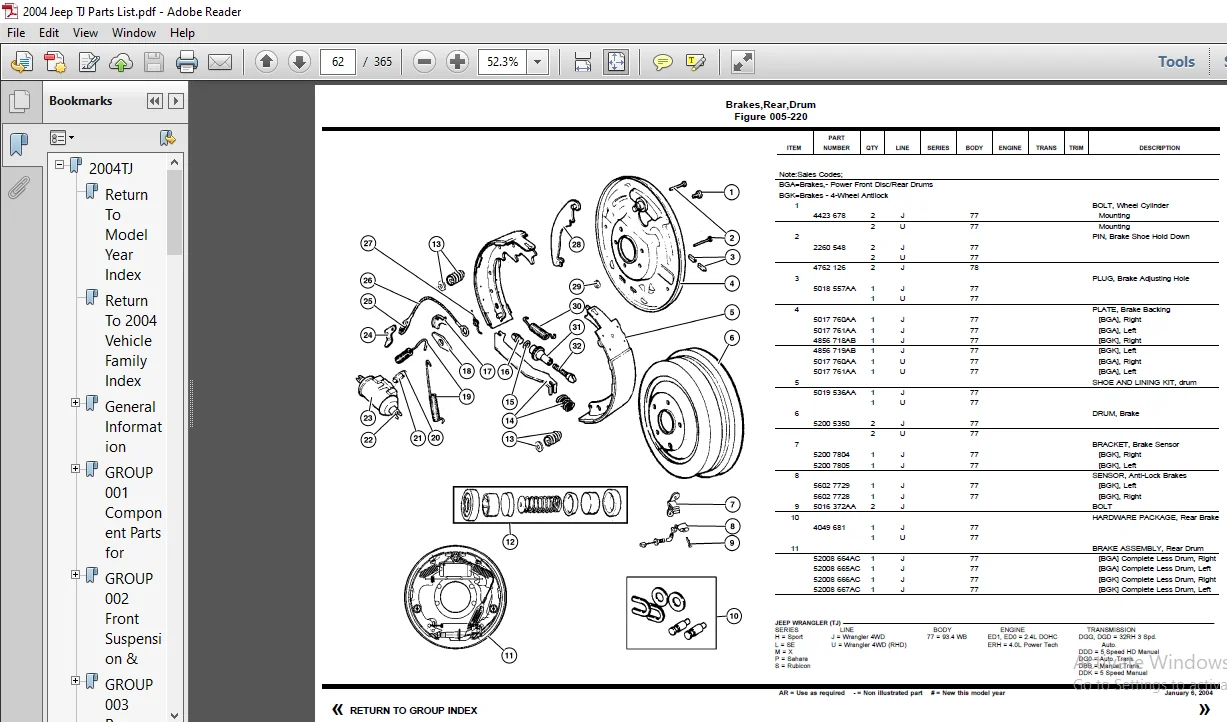
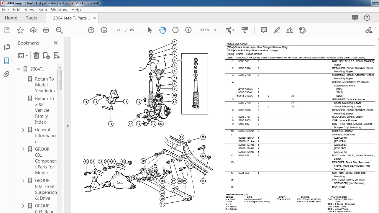
2004TJ.........................................................................................  1
	Return To Model Year Index.................................................................  0
	Return To 2004 Vehicle Family Index........................................................  0
	General Information........................................................................  1
		Abbreviations..........................................................................  7
		Alphabetic Index.......................................................................  6
		Body Code Plate Interpretation.........................................................  7
		Catalog Groups - Titles & Contents.....................................................  2
		How to Use This Catalog and Locate Parts...............................................  5
		Illustration Index.....................................................................  6
		Illustration Numbering Index...........................................................  5
		Index..................................................................................  1
		Logical Illustration Index.............................................................  2
		Logical Illustrations..................................................................  5
		Numerical Index........................................................................  6
		Page Numbering.........................................................................  5
		Part Packages..........................................................................  6
		Standard Parts.........................................................................  6
		Symbols Used in this Catalog...........................................................  5
		VIN Plate Decoding Information.........................................................  6
	GROUP  001  Component Parts for Mopar Accessories..........................................  8
		FIGURE 001-110 -->Player Kit - CD - Changher - 6 Disc..................................  9
		FIGURE 001-220 -->Bike Carrier - Hitch Mount 2 Bikes................................... 10
		FIGURE 001-222 -->Bike Carrier - Spare Tire Mount...................................... 11
		FIGURE 001-232 -->Ski Carrier - Spare Tire Mount....................................... 12
		FIGURE 001-250 -->Trailer Tow - Receiver Kit........................................... 13
		FIGURE 001-320 -->Top Kit - Soft Hardtop Replacement................................... 14
		FIGURE 001-410 -->Bumper Kit- Front Tubular............................................ 15
		FIGURE 001-420 -->Bumper Kit - Rear Tubular............................................ 16
		FIGURE 001-430 -->Extension Kit - Front Bumper......................................... 17
		FIGURE 001-440 -->Side Step Kit........................................................ 18
		FIGURE 001-510 -->Shield Kit - Air Front............................................... 19
		FIGURE 001-550 -->Hardtop Wiring Kit................................................... 20
		FIGURE 001-610 -->Light Kit - Fog...................................................... 21
		FIGURE 001-630 -->Bar Kit - Light Windshield........................................... 22
		FIGURE 001-650 -->Heater Kit - Engine Block, 4.0L Engine............................... 23
		FIGURE 001-820 -->Console Kit - Floor.................................................. 24
		FIGURE 001-910 -->Alarm - EVS Base System.............................................. 25
	GROUP  002  Front Suspension & Drive....................................................... 26
		FIGURE 002-110 -->Suspension, Front Spring with Control Arms and Track Bar............. 27
		FIGURE 002-120 -->Bar, Front Sway...................................................... 29
		FIGURE 002-210 -->Shafts, Front Axle................................................... 30
		FIGURE 002-310 -->Housing,Front Axle,4 Wheel Drive..................................... 31
		FIGURE 002-410 -->Axle Assembly,Front,4 Wheel Drive.................................... 33
		FIGURE 002-610 -->Differential,Front Axle,Without [DSE]................................ 34
		FIGURE 002-620 -->Differential,Front Axle,With [DSE]................................... 39
	GROUP  003  Rear Axle...................................................................... 41
		FIGURE 003-110 -->Axle Assembly, Rear.................................................. 42
		FIGURE 003-210 -->Housing,Rear Axle,Dana M35/194MM [DRJ]............................... 43
		FIGURE 003-220 -->Housing,Rear Axle,Dana 44/226MM [DRK]................................ 44
		FIGURE 003-230 -->Differential,With and Without Trac-Lok [DSA] Dana M35/194MM [DRJ].... 46
		FIGURE 003-240 -->Differential,With and Without Trac-Lok [DSA] Dana 44/226MM [DRK]..... 48
		FIGURE 003-250 -->Differential,With Trulok Differential [DSE] Dana 44/226MM [DRK]...... 51
		FIGURE 003-410 -->Shaft,Rear Axle,Dana 35/194MM [DRJ].................................. 52
		FIGURE 003-420 -->Shaft,Rear Axle,Dana 44/226MM [DRK].................................. 53
	GROUP  004  Parking Brake.................................................................. 54
		FIGURE 004-110 -->Parking Brake Lever and Cables....................................... 55
		FIGURE 004-120 -->Parking Brake Assembly,Rear,Disc..................................... 57
	GROUP  005  Service Brakes................................................................. 58
		FIGURE 005-110 -->Front Brakes......................................................... 59
		FIGURE 005-210 -->Brakes,Rear,Disc..................................................... 61
		FIGURE 005-220 -->Brakes,Rear,Drum..................................................... 62
		FIGURE 005-310 -->Power Brake Booster.................................................. 65
		FIGURE 005-410 -->Master Cylinder...................................................... 66
		FIGURE 005-510 -->Hydraulic Control Unit,Anti-Lock Brake............................... 67
		FIGURE 005-520 -->Brake Lines and Hoses,Front,LHD Without ABS.......................... 68
		FIGURE 005-530 -->Brake Lines and Hoses,Front,RHD,Without ABS.......................... 69
		FIGURE 005-540 -->Brake Lines and Hoses,Rear,LHD,RHD,Without ABS....................... 70
		FIGURE 005-550 -->Brake Lines and Hoses,Front,LHD With ABS............................. 71
		FIGURE 005-560 -->Brake Lines and Hoses,Rear,LHD With ABS.............................. 72
		FIGURE 005-610 -->Brake Pedal,LHD...................................................... 73
		FIGURE 005-620 -->Brake Pedal,RHD...................................................... 74
	GROUP  006  Clutch......................................................................... 75
		FIGURE 006-110 -->Clutch............................................................... 76
		FIGURE 006-210 -->Housing & Pan, Clutch................................................ 77
		FIGURE 006-310 -->Control, Clutch...................................................... 78
		FIGURE 006-410 -->Pedal, Clutch........................................................ 79
	GROUP  007  Cooling........................................................................ 80
		FIGURE 007-110 -->Radiator And Related Parts........................................... 81
		FIGURE 007-202 -->Water Pump, 2.4L Engine.............................................. 83
		FIGURE 007-205 -->Water Pump, 4.0L Engine.............................................. 84
		FIGURE 007-310 -->Tank, Coolant Recovery............................................... 85
		FIGURE 007-402 -->Drive Pulleys, 2.4L Engine........................................... 86
		FIGURE 007-405 -->Drive Pulleys, 4.0L Engine........................................... 87
		FIGURE 007-510 -->Drive Belts, 2.4L Engine............................................. 88
		FIGURE 007-515 -->Drive Belts, 4.0L Engine............................................. 89
		FIGURE 007-610 -->Oil Cooler Lines, 2.4L Engine........................................ 90
		FIGURE 007-620 -->Oil Cooler Lines, 4.0L Engine........................................ 91
		FIGURE 007-705 -->Grille And Related Parts............................................. 92
	GROUP  008  Electrical..................................................................... 93
		FIGURE 008-105 -->Starter.............................................................. 95
		FIGURE 008-205 -->Alternator 2.4L Engine............................................... 96
		FIGURE 008-210 -->Alternator 4.0L Engine............................................... 97
		FIGURE 008-405 -->Modules.............................................................. 98
		FIGURE 008-505 -->Power Distribution Center Relays and Fuses........................... 99
		FIGURE 008-510 -->Fuse Block...........................................................100
		FIGURE 008-605 -->Sensors  2.4L Engine [ED0]...........................................101
		FIGURE 008-610 -->Sensors Engine 4.0L [ER0]............................................102
		FIGURE 008-615 -->Sensors, Oxygen 2.4L [ED0]...........................................103
		FIGURE 008-620 -->Sensors Oxygen 4.0L [ER0]............................................104
		FIGURE 008-625 -->Sensors - Body.......................................................105
		FIGURE 008-630 -->Sensors Drive Train..................................................106
		FIGURE 008-705 -->Single Board Engine Controllers (JTEC Module)........................107
		FIGURE 008-805 -->Switches - Instrument Panel..........................................108
		FIGURE 008-810 -->Switches Drivetrain..................................................110
		FIGURE 008-815 -->Switches - Body......................................................111
		FIGURE 008-905 -->Horns................................................................112
		FIGURE 008-1005-->Battery Tray & Cables................................................113
		FIGURE 008-1105-->Lamps--Front.........................................................114
		FIGURE 008-1110-->Lamps--Rear..........................................................117
		FIGURE 008-1115-->Lamps--Cargo-Dome-Courtesy...........................................118
		FIGURE 008-1120-->Bulbs & Sockets......................................................119
		FIGURE 008-1205-->Wiring--Engine & Related Parts.......................................120
		FIGURE 008-1305-->Wiring--Headlamp / Dash Panel........................................122
		FIGURE 008-1405-->Wiring Instrument Panel & Fuses......................................124
		FIGURE 008-1505-->Wiring--Body & Accessory.............................................125
		FIGURE 008-1605-->Wiring Repair Packages...............................................127
		FIGURE 008-1610-->Power Distribution Center Repair.....................................128
		FIGURE 008-1705-->Air Bag Modules and Sensors..........................................129
		FIGURE 008-1710-->Air Bags and Clock Springs...........................................130
		FIGURE 008-1905-->Spark Plugs--Cables--Coil............................................131
	GROUP  08A  Instrument Panel and Radios and Consoles.......................................132
		FIGURE 08A-110 -->Instrument Panel.....................................................133
		FIGURE 08A-210 -->Instrument Cluster...................................................136
		FIGURE 08A-315 -->Radio................................................................137
		FIGURE 08A-320 -->Antenna..............................................................138
		FIGURE 08A-325 -->Speakers.............................................................139
		FIGURE 08A-410 -->Consoles Full & Mini.................................................140
	GROUP  009  Engine Mounting................................................................142
		FIGURE 009-110 -->Engine Mounting, Front, 2.4 (ED1) 4.0 (ERO)..........................143
		FIGURE 009-120 -->Engine Mounting, Rear, 2.4 (ED1) 4.0 (ERO)...........................144
	GROUP  2.4L  Engine 2.4L Four Cylinder.....................................................145
		FIGURE 2.4L-210 -->Cylinder Head, 2.4L [ED1]...........................................146
		FIGURE 2.4L-310 -->Cylinder Block, 2.4L [ED1]..........................................147
		FIGURE 2.4L-410 -->Crankshaft, Pistons and Flywheel, 2.4L [ED1]........................148
		FIGURE 2.4L-510 -->Camshaft and Valves 2.4L [ED1]......................................149
		FIGURE 2.4L-610 -->Timing Belt and Cover, 2.4L [ED1]...................................150
		FIGURE 2.4L-620 -->Balance Shafts, 2.4L [ED1]..........................................151
		FIGURE 2.4L-710 -->Engine Oiling, 2.4L [ED1]...........................................152
		FIGURE 2.4L-810 -->Intake and Exhaust Manifolds, 2.4L [ED1]............................153
		FIGURE 2.4L-910 -->Cranckcase Ventilation 2.4L [ED1]...................................154
	GROUP  4.0L  Engine 4.0L Six Cylinder......................................................155
		FIGURE 4.0L-210 -->Cylinder Head, 4.0L (ERH)...........................................156
		FIGURE 4.0L-310 -->Cylinder Block, 4.0L (ERH)..........................................157
		FIGURE 4.0L-410 -->Crankshaft, Piston and Torque Converter, 4.0L (ERH).................158
		FIGURE 4.0L-510 -->Camshaft and Valves, 4.0L (ERH).....................................160
		FIGURE 4.0L-610 -->Timing Cover, 4.0L (ERH)............................................161
		FIGURE 4.0L-710 -->Engine Oiling, 4.0L (ERH)...........................................162
		FIGURE 4.0L-810 -->Manifold, Intake and Exhaust........................................163
		FIGURE 4.0L-910 -->Crankcase Ventilation, 4.0L [ER0]...................................164
	GROUP  011  Exhaust........................................................................165
		FIGURE 011-110 -->Exhaust System, 2.4 (ED1), 4.0 (ERO).................................166
		FIGURE 011-210 -->Heat Shields, 2.4 (ED1), 4.0 (ERH)...................................167
	GROUP  013  Frames and Bumpers.............................................................168
		FIGURE 013-110 -->Frame................................................................169
		FIGURE 013-210 -->Bumper, Front........................................................172
		FIGURE 013-310 -->Bumper, Rear.........................................................174
		FIGURE 013-510 -->Body Mounting Hardware...............................................175
	GROUP  014  Fuel...........................................................................176
		FIGURE 014-110 -->Fuel Tank, 2.4 (ED1), 4.0 (ERH)......................................178
		FIGURE 014-210 -->Fuel Filler Tube, 2.4 (ED1), 4.0 (ERH)...............................179
		FIGURE 014-310 -->Fuel Lines, Front,2.4 (ED1) 4.0 (ERH)................................180
		FIGURE 014-320 -->Fuel Lines, Rear, Chassis 2.4L (ED1) 4.0 (ERH).......................181
		FIGURE 014-410 -->Fuel Injection System, 2.4 (ED1), 4.0 (ERH)..........................182
		FIGURE 014-510 -->Fuel Module, 2.4 (ED1), 4.0 (ERH)....................................183
		FIGURE 014-610 -->Throttle Body, 2.4 (ED1), 4.0 (ERH)..................................184
		FIGURE 014-710 -->Throttle Controls, 2.4 (ED1), 4.0 (ERH)..............................185
		FIGURE 014-810 -->Air Cleaner, 2.4 (ED1), 4.0 (ERH)....................................186
		FIGURE 014-1010-->Speed Control, 2.4 (ED1), 4.0 (ERH)..................................187
		FIGURE 014-1110-->Accelerator Pedal, 2.4 (ED1), 4.0 (ERH)..............................188
	GROUP  016  Propeller Shafts and U-Joints..................................................189
		FIGURE 016-110 -->Propshaft,Front and Rear.............................................190
	GROUP  017  Rear Suspension................................................................192
		FIGURE 017-110 -->Suspension, Rear  with Shocks,Springs and Track Bar..................193
		FIGURE 017-210 -->Stabilzer, Rear......................................................195
	GROUP  019  Steering.......................................................................196
		FIGURE 019-110 -->Wheel, Steering......................................................197
		FIGURE 019-210 -->Column, Steering Upper and Lower.....................................198
		FIGURE 019-310 -->Gear, Power Steering.................................................200
		FIGURE 019-410 -->Linkage and Damper...................................................201
		FIGURE 019-510 -->Pump, Power Steering.................................................203
		FIGURE 019-710 -->Hoses and Reservoir, 2.4L Engine [ED0]...............................204
		FIGURE 019-720 -->Hoses and Reservoir,4.0L Engine [ER0]................................205
	GROUP  42RLE  Automatic Transaxle 4 Speed..................................................206
		FIGURE 42RLE-110 -->Transaxle Assembly [DG6]...........................................207
		FIGURE 42RLE-120 -->Mounting, Transmission [ED1 + DG6].................................208
		FIGURE 42RLE-130 -->Mounting, Transmission [ERH + DG6].................................209
		FIGURE 42RLE-210 -->Transmission Case [DG6]............................................210
		FIGURE 42RLE-220 -->Adapter, Rear [DG6]................................................211
		FIGURE 42RLE-310 -->Oil Pump & Reaction Shaft [DG6.....................................212
		FIGURE 42RLE-410 -->Clutch, Input Shaft [DG6]..........................................213
		FIGURE 42RLE-420 -->Gear Train [DG6]...................................................218
		FIGURE 42RLE-710 -->Valve Body [DG6]...................................................225
		FIGURE 42RLE-720 -->Accumulator Piston & Springs [DG6].................................228
		FIGURE 42RLE-730 -->Parking Sprag [DG6]................................................229
		FIGURE 42RLE-1210-->Gearshift Controls [DG6]...........................................230
	GROUP  3550  Manual Transmission 5 Speed...................................................231
		FIGURE 3550-110 -->Transmission  (DDD).................................................232
		FIGURE 3550-210 -->Case and Extension  (DDD)...........................................233
		FIGURE 3550-410 -->Gear Train (DDD)....................................................235
		FIGURE 3550-910 -->Fork and Rails (DDD)................................................239
		FIGURE 3550-1210-->Gearshift Controls (DDD)............................................240
	GROUP  NV2550  Manual Transmission 5 Speed.................................................241
		FIGURE NV2550-110 -->Transmission [NV 2550] [DDK]......................................242
		FIGURE NV2550-210 -->Case and Extension  [NV 2550]  [DDK]..............................243
		FIGURE NV2550-410 -->Gear Train  [NV 2550] [DDK].......................................245
		FIGURE NV2550-910 -->Fork and Rail  [NV 2550]  [DDK]...................................247
		FIGURE NV2550-1210-->Gearshift Controls................................................248
	GROUP  231  Transfer Case Model 231........................................................249
		FIGURE 231-110 -->Command Trac Transfer Case  [DHN]....................................250
		FIGURE 231-210 -->Case & Related Parts, Command Trac [DHN].............................251
		FIGURE 231-410 -->Gear Train, Command Trac [DHN].......................................255
		FIGURE 231-910 -->Forks & Rails, Command Trac [DHN]....................................259
		FIGURE 231-1210-->Gearshift Controls, Command Trac [DHN]...............................261
	GROUP  241  Transfer Case Model 241........................................................263
		FIGURE 241-110 -->Transfer Case  [DHW].................................................264
		FIGURE 241-210 -->Case Transfer & Related Parts [DHW]..................................265
		FIGURE 241-410 -->Gear Train [DHW].....................................................267
		FIGURE 241-910 -->Forks  [DHW].........................................................268
		FIGURE 241-1210-->Controls   [DHW].....................................................269
	GROUP  21P  Speedometer Pinions............................................................271
		FIGURE 21P-110 -->Speedometer Pinion & Housing.........................................272
	GROUP  022  Wheels, Covers and Jacks.......................................................273
		FIGURE 022-110 -->Wheels...............................................................274
		FIGURE 022-210 -->Caps And Covers......................................................275
		FIGURE 022-310 -->Jack And Storage.....................................................276
		FIGURE 022-410 -->Wheel, Spare Tailgate Mounted........................................277
	GROUP  23D  Wiper/Lock Cylinder and Keys...................................................278
		FIGURE 23D-105 -->Lock Cylinders & Keys................................................279
		FIGURE 23D-205 -->Wiper System Front...................................................281
		FIGURE 23D-305 -->Rear Wiper System....................................................282
	GROUP  024  Air Conditioning & Heater......................................................283
		FIGURE 024-105 -->Hevac Unit, LHD......................................................284
		FIGURE 024-110 -->Hevac Unit, RHD......................................................285
		FIGURE 024-210 -->Hoses, Heater 2.4L Engine............................................286
		FIGURE 024-220 -->Hoses, Heater 4.0L Engine............................................287
		FIGURE 024-225 -->Plumbing, Hevac 2.4L Engine..........................................288
		FIGURE 024-235 -->Plumbing, Hevac 4.0L Engine, LHD.....................................289
		FIGURE 024-240 -->Pluming, Hevac 4.0L Engine, RHD......................................290
		FIGURE 024-245 -->Seals, A/C Condenser.................................................291
		FIGURE 024-310 -->Control, Heater And A/c..............................................292
		FIGURE 024-410 -->Compressor, Air Conditioning.........................................293
		FIGURE 024-610 -->Ducts, Heater And A/c................................................294
	GROUP  025  Emission Systems...............................................................295
		FIGURE 025-310 -->Vacuum Canister, 2.4 (ED1), 4.0 (ERH)................................296
		FIGURE 025-410 -->Emission Control Vacuum Harness, 2.4 (EP1), 4.0 (ERH)................297
		FIGURE 025-420 -->Leak Detection Pump, 2.4 (ED1), 4.0 (ERH)............................298
	GROUP  DTJ  Doors and Related Parts........................................................299
		FIGURE DTJ-110 -->Door, Full Front Shell And Hinges....................................300
		FIGURE DTJ-120 -->Door, Full Front Glass And Regulator.................................301
		FIGURE DTJ-130 -->Door, Full Front Lock And Controls...................................302
		FIGURE DTJ-160 -->Door, Half Front Shell And Hinges....................................303
		FIGURE DTJ-170 -->Door, Half Front Lock And Controls...................................304
		FIGURE DTJ-510 -->Mirror, Exterior.....................................................305
		FIGURE DTJ-610 -->Door Weatherstrips And Runs..........................................306
	GROUP  ETJ  Exterior Ornamentation.........................................................307
		FIGURE ETJ-210 -->Mouldings............................................................308
		FIGURE ETJ-310 -->Decals...............................................................309
	GROUP  ITJ  Interior Trim..................................................................310
		FIGURE ITJ-110 -->Sunvisors............................................................311
		FIGURE ITJ-210 -->Panels, Interior Trim, Front.........................................312
		FIGURE ITJ-310 -->Carpets And Interior Trim Panels.....................................313
		FIGURE ITJ-410 -->Door Trim Panels Half Doors & Full Doors.............................314
		FIGURE ITJ-510 -->Front Vinyl, Trim Code [H6]..........................................315
		FIGURE ITJ-520 -->Front, Cloth, Trim Code [P5].........................................317
		FIGURE ITJ-530 -->Front, Cloth, Trim Code [S5].........................................319
		FIGURE ITJ-540 -->Front, Cloth, Trim Code [Q5].........................................321
		FIGURE ITJ-550 -->Front, Cloth, Trim Code [L5].........................................322
		FIGURE ITJ-560 -->Front, Cloth, Trim Code [H5].........................................323
		FIGURE ITJ-610 -->Rear, Vinyl, Trim Code [H6]..........................................324
		FIGURE ITJ-620 -->Rear, Cloth, Trim Code [P5]..........................................326
		FIGURE ITJ-630 -->Rear, Cloth, Trim Code [S5]..........................................328
		FIGURE ITJ-640 -->Rear, Cloth, Trim Code [Q5]..........................................329
		FIGURE ITJ-650 -->Rear, Cloth, Trim Code [L5]..........................................330
		FIGURE ITJ-660 -->Rear, Cloth, Trim Code [H5]..........................................331
		FIGURE ITJ-710 -->Seat Belts...........................................................332
		FIGURE ITJ-810 -->Seat Assemblies, Adjusters, Recliners................................334
	GROUP  STJ  Body Sheet Metal Except Doors..................................................341
		FIGURE STJ-210 -->Pan, Floor Front And Rear, Body Style 77.............................343
		FIGURE STJ-220 -->Pan, Floor Front And Rear, Body Style 78.............................344
		FIGURE STJ-310 -->Plugs................................................................345
		FIGURE STJ-410 -->Fender And Flare, Front..............................................346
		FIGURE STJ-510 -->Hood, Lock, Catches..................................................347
		FIGURE STJ-610 -->Panels, Cowl And Dash................................................348
		FIGURE STJ-710 -->Glass, Windshield, Backlite, Quarter Windshield Frame, Hinges........349
		FIGURE STJ-810 -->Panels, Body Side....................................................351
		FIGURE STJ-1110-->Soft Top And Windows.................................................353
		FIGURE STJ-1120-->Top Enclosure, Hard..................................................355
		FIGURE STJ-1310-->Tailgate.............................................................356
		FIGURE STJ-1320-->Add-a-Trunk..........................................................358
		FIGURE STJ-1610-->Sport Bar Wrangler...................................................359
	GROUP  LBLS  Labels All Vehicle Locations..................................................361
		FIGURE LBLS-110 -->Instrument Panel, Visors and Trim...................................362
		FIGURE LBLS-210 -->Engine Compartment..................................................363
		FIGURE LBLS-310 -->Doors and Pillars...................................................364
		FIGURE LBLS-410 -->Spare Tire..........................................................365
	End of Catalog.............................................................................361
Questions? Email us: [email protected]
IMAGES PREVIEW OF THE MANUAL:
PLEASE NOTE:
- This is the SAME manual used by the dealers to troubleshoot any faults in your vehicle. This can be yours in 2 minutes after the payment is made.
- Contact us at [email protected] should you have any queries before your purchase or that you need any other service / repair / parts operators manual.
S.V