2007 Cummins ISX CM850 CM870 & CM875 Common Approach To Control System Diagnostics Manual – PDF DOWNLOAD
$20.95
2007 Cummins ISX CM850 CM870 & CM875 Common Approach To Control System Diagnostics Manual – PDF DOWNLOAD
Description
2007 Cummins ISX CM850 CM870 & CM875 Common Approach To Control System Diagnostics Manual – PDF DOWNLOAD
FILE DETAILS:
2007 Cummins ISX CM850 CM870 & CM875 Common Approach To Control System Diagnostics Manual – PDF DOWNLOAD
Language : English
Pages : 80
Downloadable : Yes
File Type : PDF
IMAGES PREVIEW OF THE MANUAL:
DESCRIPTION:
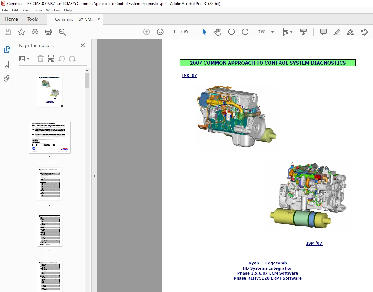
2007 Cummins ISX CM850 CM870 & CM875 Common Approach To Control System Diagnostics Manual – PDF DOWNLOAD
Overview:
- This document is intended to support on-site troubleshooting and diagnostics of customer complaints for 2007 Heavy-Duty engine platforms. This document can be used along with NGET or Calterm II (ERPT) or CalTerm III (ECM) for investigation, troubleshooting, and diagnosis of engine performance and electronic controls related issues.
Purpose:
- The information contained in this document is based on information from Simulink Diagrams and Code Files. The 2007 HD control system includes new control strategies for Air Handling and emissions to meet the 2007 requirements. Information on troubleshooting and diagnostics for these systems is included here.
- My intent for this document is to provide information and support to those in the field as well as those based in Cummins engineering facilities. With tools like NGET and Calterm (II and III), documentation of data within this document will provide more detailed definition of engine conditions associated with specific issues.
- This information, along with driver comments and concerns, will help in achieving a better responsiveness to customer needs and allow us to develop products which meet or exceed customer expectations.
INSTRUCTION FOR USING THE EXTERNAL (MONITOR) DATA LOGGER
1. Launch Calterm III
2. If Calterm doesn’t automatically bring up the Select Module screen, go to File and select Open Module
3. Verify the settings on the Datalink tab are set according to your chosen datalink
4. For one-module engines or if you desire to connect to multiple modules using one ecfg file, select Automatic
5. For multi-module engines, Select Manual and type the ECM Address in the first column followed by the appropriate ECFG or E2M file in the second for each module you will connect to,
then click OK
6. Once connected a default Monitor screen will be displayed
7. Either type the parameter names in the monitor screen (use F1 to help search for parameter names) or select a specific screen from the Monitor drop down / Open Screen File.
8. Once the screen is set up appropriately, click on the Start button to begin recording
9. Click on Stop to stop recording and name and save your file
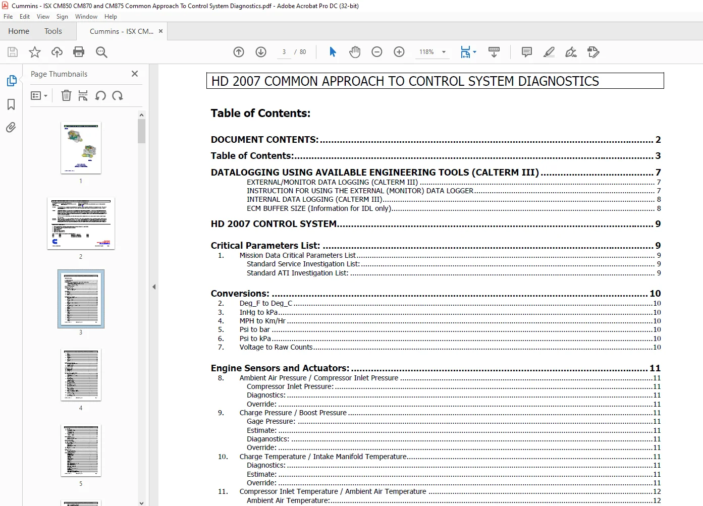
TABLE OF CONTENTS:
2007 Cummins ISX CM850 CM870 & CM875 Common Approach To Control System Diagnostics Manual – PDF DOWNLOAD
DOCUMENT CONTENTS: 2
Table of Contents: 3
DATALOGGING USING AVAILABLE ENGINEERING TOOLS (CALTERM III) 7
EXTERNAL/MONITOR DATA LOGGING (CALTERM III) 7
INSTRUCTION FOR USING THE EXTERNAL (MONITOR) DATA LOGGER 7
INTERNAL DATA LOGGING (CALTERM III) 8
ECM BUFFER SIZE (Information for IDL only) 8
HD 2007 CONTROL SYSTEM 9
Critical Parameters List: 9
1 Mission Data Critical Parameters List 9
Standard Service Investigation List: 9
Standard ATI Investigation List: 9
Conversions: 10
2 Deg_F to Deg_C 10
3 InHg to kPa 10
4 MPH to Km/Hr 10
5 Psi to bar 10
6 Psi to kPa 10
7 Voltage to Raw Counts 10
Engine Sensors and Actuators: 11
8 Ambient Air Pressure / Compressor Inlet Pressure 11
Compressor Inlet Pressure: 11
Diagnostics: 11
Override: 11
9 Charge Pressure / Boost Pressure 11
Gage Pressure: 11
Estimate: 11
Diaganostics: 11
Override: 11
10 Charge Temperature / Intake Manifold Temperature 11
Diagnostics: 11
Estimate: 11
Override: 11
11 Compressor Inlet Temperature / Ambient Air Temperature 12
Ambient Air Temperature: 12
Diagnostics: 12
Override: 12
12 Coolant Level 12
Diagnostics: 12
Override: 12
13 Coolant Temperature 12
Override: 12
Diagnostics: 12
14 EGR Delta Pressure 12
Autozero: 12
In-Range: 12
Diganostics: 12
Override: 12
15 EGR Orifice Temperature 13
Override: 13
Diagnostics: 13
16 EGR Valve Actuator 13
Override: 13
Diagnostics: 13
17 Exhaust Pressure 13
In-Range: 13
Estimate: 13
Diagnostics: 13
HD 2007 COMMON APPROACH TO CONTROL SYSTEM DIAGNOSTICS
Cummins , Inc Confidential Created by Ryan E Edgecomb Page 4
Override: 13
18 Oil Pressure 13
Override: 13
Diagnostics: 13
19 Oil Temperature 13
Override: 13
Diagnostics: 13
20 Turbocharger Speed 14
Diagnostics: 14
Estimate: 14
Override: 14
21 Turbocharger VG Actuator 14
Diagnostics: 14
Override: 14
HPI-TP Fuel Systems Sensors: 15
22 EPS (Engine Position / Engine Speed) Sensors 15
EPS Main Sensor (Crank): 15
EPS Backup Sensor (Cam): 15
23 Fuel Rail Pressure Sensor 15
Diagnostics: 15
24 Fuel Temperature Sensor 15
Aftertreatment Sensors: 16
25 DOC Inlet Thermistor 16
26 DOC Outlet Thermistor 16
27 RPF Outlet Thermistor 16
28 RPF Delta P Sensor 16
29 Doser Fuel Pressure 16
Parameter Estimates and Predictions: 17
30 Ambient Parameters Estimate 17
Ambient Air Temperature Estimate: 17
Altitude Estimate: 17
Humidity Estimation (engineering use only): 17
31 Charge Flow Estimate 17
Estimate: 17
Volumetric Efficiency: 17
Speed Density Equation: 17
32 Charge Pressure Estimate 18
Estimate With Turbo Speed 18
Estimate Without Turbo Speed 18
Status with Turbo Speed: 18
Status without Turbo Speed: 18
33 Charge Temperature Estimate 18
34 Compressor Inlet Density Estimate 18
Estimate: 18
Source: 18
35 Compressor Inlet Pressure Estimate 18
Compressor Inlet Pressure Estimate: 18
36 Compressor Outlet Temperature Estimate 19
COT Estimate: 19
COT Estimate Source: 19
37 EGR Fraction Estimate 19
EGR Fraction Estimate: 19
Downstream EGR Flow Model: 19
Upstream EGR Flow Model: 19
38 EGR Valve and Engine Delta Pressure Estimates 19
EGR Valve and Engine Delta Pressure Estimate: 19
EGR Valve and Engine Delta Pressure Estimate Source: 19
39 Exhaust Flow Estimation 19
40 Exhaust Pressure Estimate 20
Exhaust Pressure Estimate: 20
Exhaust Pressure Estimate Source: 20
41 Exhaust Temperature Estimate 20
Exhaust Temperature Estimate: 20
42 Fresh Air Flow Estimation 20
HD 2007 COMMON APPROACH TO CONTROL SYSTEM DIAGNOSTICS
Cummins , Inc Confidential Created by Ryan E Edgecomb Page 5
43 IMT Prediction 20
44 IMT Lead-Lag Compensation 20
45 Saturation Temperature Estimate 21
Saturation Temperatures Estimate: 21
Charge H2O Mole Fraction: 21
Inlet Mole Fraction of Water: 21
Exhaust H2O Mole Fraction: 21
Saturation Temperature Source 21
46 Turbo Speed Estimation 21
Turbo Speed Estimate Logic: 21
Turbo Speed Estimate Status: 21
Emission Features: 22
47 Charge Limit Management (CHL) 22
[CHL] EGR Fraction Limit Selection: 22
[CHL] Mass Charge Flow Limit Selection: 22
48 Charge System Errors (CSE) 23
Performance Diagnostics: 24
49 Aftertreatment Doser Diagnostics 24
50 Aftertreatment Regeneration / Triggers 24
51 Aftertreatment Soot Load 24
Charge Limit Management (CHL) 25
[CHL] COT Limiter: 25
[CHL] Turbo Speed Limiter: 25
[CHL] EGR Delta Pressure Limiter: 25
[CHL] EGR Off Delta Pressure Limiter: 25
[CHL] Surge Limiter: 26
52 FELIX 26
53 Stationary Regeneration / OSCAR 26
54 User Overrides 27
HPI-TP Fuel System: 29
55 Cylinder Cut-Out Diagnostics (CTS) 29
Fuel Actuator Addition Time-On Trims: 29
Timing Actuator Additional Time-On Trims: 29
CM870 ENGINEERING STATES 30
BINARY DEFINITION: 30
HEXADECIMAL DEFINITION: 30
ACCELERATOR GOVERNOR: 31
ACCELERATOR INTERLOCK: 31
AFTERTREATMENT: 31
CHANGE LOCK: 34
CHARGE FLOW: 34
CRUISE CONTROL: 34
CYLINDER PERFORMANCE: 34
DATALINK: 35
DRIVER REWARD: 35
EGR FRACTION: 35
EGR Valve: 36
EMISSION MANAGER: 36
ENGINE BRAKE: 36
ENGINE OPERATING CONDITION (ALPHA / Chi): 37
ENGINE PROTECTION: 37
ENGINE SOI TIMING COMMAND: 38
ENGINE SPEED PROCESSING (EPS): 38
ENGINE STATES: 38
ENGINE TORQUE / FUEL COMMAND: 40
FAN CONTROL: 42
FAST IDLE WARMUP: 42
GEAR DOWN / OUT OF GEAR PROTECTION: 42
HOT SHUTDOWN: 42
IDLE VALIDATION: 42
POWER TAKE OFF (PTO): 43
SENSOR ERROR INFORMATION (IN-RANGE):: 43
SENSOR SOURCE INFORMATION (A/D SENSORS): 43
SENSOR SOURCE INFORMATION (ESTIMATES AND VIRTUAL): 43
HD 2007 COMMON APPROACH TO CONTROL SYSTEM DIAGNOSTICS
Cummins , Inc Confidential Created by Ryan E Edgecomb Page 6
SENSOR STATE INFORMATION (A/D SENSORS): 43
SENSOR STATE INFORMATION (ESTIMATES): 43
SENSOR STATUS INFORMATION (A/D SENSORS):: 44
SENSOR CONFIDENCE INFORMATION (A/D SENSORS):: 44
SETUP FOR DYNO: 44
STATIONARY REGENERATION: 44
TRIP INFORMATION: 45
VEHICLE SPEED SENSOR: 45
VGT: 46
WATER-IN-FUEL (WIF): 47
CM870 and CM875 FAULT CODE LIST 48
Air Handling Control System Overview: 63
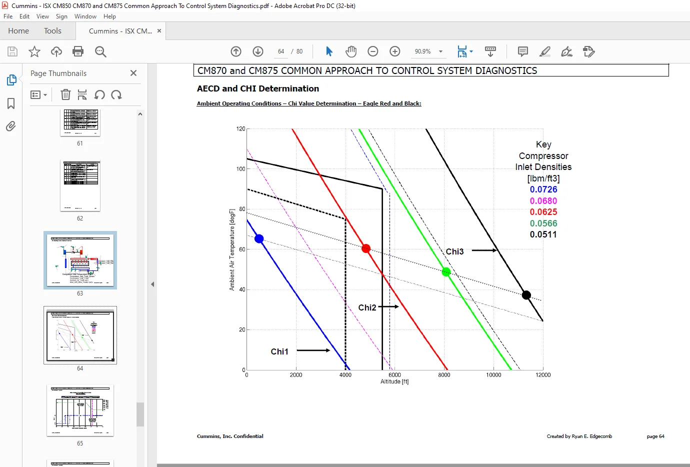
AECD and CHI Determination 64
Ambient Operating Conditions – Chi Value Determination – Eagle Red and Black: 64
IMT Based Actions – Eagle Red 65
Coolant Based Actions – Eagle Red 67
Coolant Based Actions – Eagle Black 68
EGR Outlet Temperature Based Actions – Eagle Red 69
EGR Outlet Temperature Based Actions – Eagle Black 70
Stationary Regeneration Procedure 71
CUSTOMER / DRIVER SURVEY 72
Customer Information 72
Typical Driving Techniques 73
Engine Start 73
Engine Idle 74
Engine PTO Operation 74
Clutch Engagement 75
Clutch Engagement (cont ) 76
Cruise Control 77
Driver Input 77
Engine Response 78
Low Speed Maneuvering 78
Engine Brake in Cruise Feature 78
EGR / VGT Control System 79
NOTES 80
Contact us: [email protected]
S.V