2007 Cummins ISX CM871 CM876 Common Approach To Control System Diagnostics Manual – PDF DOWNLOAD
$27.95
2007 Cummins ISX CM871 CM876 Common Approach To Control System Diagnostics Manual – PDF DOWNLOAD
Description
2007 Cummins ISX CM871 CM876 Common Approach To Control System Diagnostics Manual – PDF DOWNLOAD
FILE DETAILS:
2007 Cummins ISX CM871 CM876 Common Approach To Control System Diagnostics Manual – PDF DOWNLOAD
Language : English
Pages : 154
Downloadable : Yes
File Type : PDF
IMAGES PREVIEW OF THE MANUAL:
DESCRIPTION:
2007 Cummins ISX CM871 CM876 Common Approach To Control System Diagnostics Manual – PDF DOWNLOAD
Overview:
This document is intended to support on-site troubleshooting and diagnostics of customer complaints
for 2007 Heavy-Duty engine platforms. This document can be used along with CalTerm III for
investigation, troubleshooting, and diagnosis of engine performance and electronic controls related
issues.
Purpose:
The information contained in this document is based on information from Simulink Diagrams and Code
Files. The 2007 HD control system includes new control strategies for Air Handling and emissions to
meet the 2007 requirements. Information on troubleshooting and diagnostics for these systems is
included here. The intent for this document is to provide information and support to those in the
field as well as those based in Cummins engineering facilities. This document along with Calterm
III will provide more detailed definition of engine conditions associated with specific issues.
This information, along with driver comments and concerns, will help in achieving a better
responsiveness to customer needs and allow us to develop products which meet or exceed customer
expectations.
Instructions for using the EDM Data logger:
1. Lauch Calterm III
2. The monitor screen should be displayed. If Calterm does not automatically display the Select Module Screen, go to File and select Open Module.
3. On the monitor screen, select Module Type and ECFG file. ECFG files for each software phase can be downloaded at the following link:
http://www.jep.cummins.com/teams/pde/index_org.html
4. Click Automatic to connect to the module. Once connected, the default monitor screen will be displayed
5. If unable to connect, go to Tools, select Options and click datalink type – Verify the settings on the Datalink tab are configured to work with an Inline 5 adapter.
6. Once connected, add parameters to the monitor screen or open an existing screen file.
– To add parameters to the monitor screen, change the data collection mode to EDM. Type the parameter name or use F1 to search for parameters.
– To open an existing screen file, go to Monitor and select open screen file.
7. Depending on the desired data collection rate, add parameters to achieve a maximum data rate of 20 bits/ms.
-To determine the number of bits for a given parameter, open the ecfg file using word pad. Search for the the parameter name. Under the parameter name, data_length will be listed.
-The majority of parameters are 2 bits. For example, the data length of FSS_Total_Fueling is 2 bits.
-To determine the data rate, add the bits from all parameter on the screen file and divide by the desired data collection rate.
-For example, at a rate of 20 bits/ms, 40 two bit parameters can be collected every 20ms.
8. Change the data collection mode to EDM. Select the desired data monitor rate.
9. If parameter values are not displayed on the screen after switching to EDM mode, you may have too many parameters for the data collection rate. Two options for correcting this are
a. Decrease number of parameters (Use only recommended parameters from this document).
b. Decrease the data collection rate
-The data rate of 20 bits/min is only possible under ideal conditions. Increased datalink traffic will decrease the allowable data rate.
10. To start data collection click on start
11. To stop data collection click stop
12. Save datafile to desired location
TABLE OF CONTENTS:
2007 Cummins ISX CM871 CM876 Common Approach To Control System Diagnostics Manual – PDF DOWNLOAD
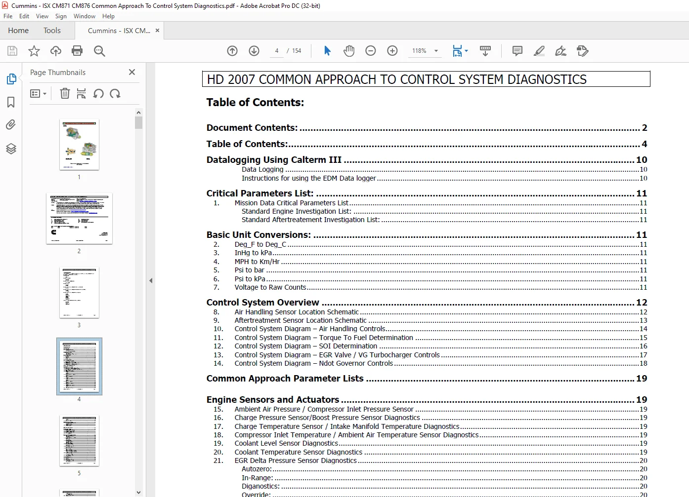
Document Contents: 2
Table of Contents: 4
Datalogging Using Calterm III 10
Data Logging 10
Instructions for using the EDM Data logger 10
Critical Parameters List: 11
1 Mission Data Critical Parameters List 11
Standard Engine Investigation List: 11
Standard Aftertreatement Investigation List: 11
Basic Unit Conversions: 11
2 Deg_F to Deg_C 11
3 InHg to kPa 11
4 MPH to Km/Hr 11
5 Psi to bar 11
6 Psi to kPa 11
7 Voltage to Raw Counts 11
Control System Overview 12
8 Air Handling Sensor Location Schematic 12
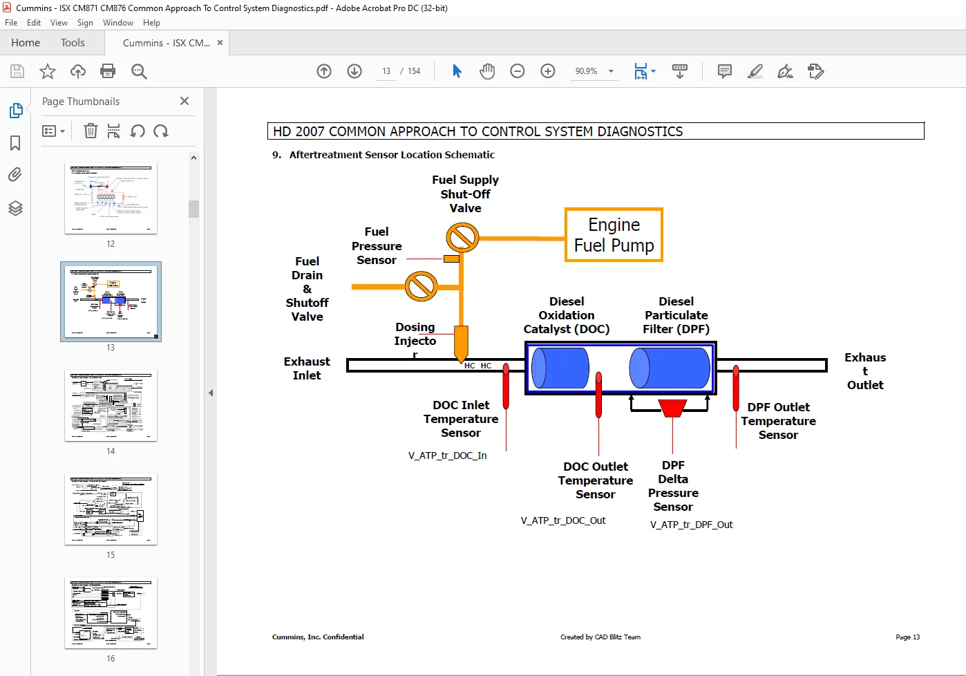
9 Aftertreatment Sensor Location Schematic 13
10 Control System Diagram – Air Handling Controls 14
11 Control System Diagram – Torque To Fuel Determination 15
12 Control System Diagram – SOI Determination 16
13 Control System Diagram – EGR Valve / VG Turbocharger Controls 17
14 Control System Diagram – Ndot Governor Controls 18
Common Approach Parameter Lists 19
Engine Sensors and Actuators 19
15 Ambient Air Pressure / Compressor Inlet Pressure Sensor 19
16 Charge Pressure Sensor/Boost Pressure Sensor Diagnostics 19
17 Charge Temperature Sensor / Intake Manifold Temperature Diagnostics 19
18 Compressor Inlet Temperature / Ambient Air Temperature Sensor Diagnostics 19
19 Coolant Level Sensor Diagnostics 19
20 Coolant Temperature Sensor Diagnostics 19
21 EGR Delta Pressure Sensor Diagnostics 20
Autozero: 20
In-Range: 20
Diganostics: 20
Override: 20
22 EGR Orifice Temperature Sensor Diagnostics 20
Override: 20
Diagnostics: 20
23 EGR Valve Actuator Diagnostics 20
Override: 20
Diagnostics: 20
24 Exhaust Pressure Sensor Diagnostics 20
In-Range: 20
Estimate: 20
Diagnostics: 20
Override: 20
25 Oil Pressure Sensor Diagnostics 21
Override: 21
Diagnostics: 21
26 Oil Temperature Sensor Diagnostics 21
Override: 21
Diagnostics: 21
27 Turbocharger Speed Sensor Diagnostics 21
Diagnostics: 21
Estimate: 21
Override: 21
28 Turbocharger VG Actuator Diagnostics 21
HD 2007 COMMON APPROACH TO CONTROL SYSTEM DIAGNOSTICS
Cummins , Inc Confidential Created by CAD Blitz Team Page 5
Diagnostics: 21
Override: 21
29 Open Crankcase Ventilation 21
HPI-TP Fuel System Sensors: 22
30 EPS (Engine Position / Engine Speed) Sensors 22
EPS Main Sensor (Crank): 22
EPS Backup Sensor (Cam): 22
31 Fuel Rail Pressure Sensor 22
Diagnostics: 22
32 Fuel Temperature Sensor 22
CELECT Fuel System Sensors: 22
Aftertreatment Sensors: 22
33 DOC Inlet Thermistor Sensor Diagnostics 22
34 DOC Outlet Thermistor Sensor Diagnostics 22
35 DPF Outlet Thermistor Sensor Diagnostics 22
36 DPF Delta P Sensor Diagnostics 22
37 Doser Fuel Pressure Sensor Diagnostics 23
38 Shut Off Valve Sensor Diagnostics 23
39 Doser Actuator Diagnostics 23
Parameter Estimates and Predictions: 24
40 Ambient Parameters Estimate 24
Ambient Air Temperature Estimate: 24
Altitude Estimate: 24
Humidity Estimation (engineering use only): 24
41 Charge Flow Estimate 24
Estimate: 24
Volumetric Efficiency: 24
Speed Density Equation: 24
42 Charge Pressure Estimate 24
Estimate With Turbo Speed 24
Estimate Without Turbo Speed 24
Status with Turbo Speed: 24
Status without Turbo Speed: 24
43 Charge Temperature Estimate 25
44 Compressor Inlet Density Estimate 25
Estimate: 25
Source: 25
45 Compressor Inlet Pressure Estimate 25
46 Compressor Outlet Temperature Estimate 25
COT Estimate: 25
COT Estimate Source: 25
47 EGR Fraction Estimate 25
EGR Fraction Estimate: 25
Downstream EGR Flow Model: 25
48 EGR Valve and Engine Delta Pressure Estimates 26
EGR Valve and Engine Delta Pressure Estimate: 26
EGR Valve and Engine Delta Pressure Estimate Source: 26
49 Exhaust Flow Estimation 26
50 Exhaust Pressure Estimate 26
Exhaust Pressure Estimate: 26
Exhaust Pressure Estimate Source: 26
51 Exhaust Temperature Estimate 26
Exhaust Temperature Estimate: 26
52 Fresh Air Flow Estimation 26
53 IMT Prediction 26
54 IMT Lead-Lag Compensation 27
55 NOx Estimation 27
56 O2 Estimation 27
57 Particulate Matter Estimation 27
58 Robust Torque Model / Torque to Fuel 27
59 Saturation Temperature Estimate 28
Saturation Temperature Estimate: 28
Charge H2O Mole Fraction: 28
HD 2007 COMMON APPROACH TO CONTROL SYSTEM DIAGNOSTICS
Cummins , Inc Confidential Created by CAD Blitz Team Page 6
Inlet Mole Fraction of Water: 28
Exhaust H2O Mole Fraction: 28
Saturation Temperature Source 28
60 Turbine Out Temperature Estimation 28
61 Turbo Speed Estimation 28
Turbo Speed Estimate 28
Turbo Speed Estimate Status 28
62 UHC (Unburned HydroCarbon) Estimation 29
63 Unburned Hydrocarbon Timing Control (UHC IMT/Coolant Advance) 29
After-Treatment Diagnostics 30
64 Aftertreatment Out-of-Range and In-Range Diagnostics 30
65 After-Treatment System Diagnostics 30
66 Dosing System Diagnostics 31
67 After-treatment Temperature Diagnostics 31
68 After-Treatment Lamp User Interface 32
69 Dosing System Diagnostics – FC 1926, 1927, 1932, and 2741 32
70 DeltaP Key-On Diagnostic – FC 1883 32
71 DeltaP Dither Diagnostic – FC 1883 32
72 Reversed Thermistors Diagnostics – FC 1663 33
73 Thermistors Key-On Diagnostic – FC 1667 33
74 Thermistors Key-On Diagnostic – FC 1676 33
75 Thermistors Key-On Diagnostic – FC 1878 33
76 High Temperature Faults – FC 1968 33
77 High Temperature Faults – FC 1969 33
78 High Temperature Faults – FC 1972 33
79 High Temperature Faults – FC 1973 34
80 Dither Faults – FC 1667 34
81 Dither Faults – FC 1676 34
82 Dither Faults – FC 1878 34
83 Ineffective Regenerations – FC 2728 34
84 DOC Presence – FC 1664 34
85 DOC Efficiency – FC 2638 35
86 DOC Efficiency – FC 1691 35
87 DOC Face Plugged – FC 2637 35
88 DPF Missing – FC 1993 35
89 DPF Plugged – FC 1981 35
90 DPF High DeltaP – FC 1981 35
91 Engine Out Temp (Stationary) – FC 2742 and 2743 35
92 Engine Out PM – FC 2754 36
93 Soot Load – FC 2639, 1921, and 1922 36
After-Treatment System Performance 36
94 Stationary Regeneration and Desorb Enable Conditions 36
95 Stationary and Mobile Regeneration 36
96 Stationary and Mobile H20 Desorption 36
97 Stationary and Mobile HC Desorption 37
After-Treatment Parameter Estimates 37
98 Engine Out PM Estimate 37
99 DeltaP Soot Load Estimate 37
100 Mass Balanced Soot Load Estimate 37
Aftertreatment Overrides 38
101 User Overrides 38
102 User Resets 38
Procedures 39
103 Soot Load Override 39
104 Trigger Stationary Regeneration without the Stationary Regen Switch 39
105 Stationary Regeneration Pedal Dance Procedure 39
106 After-treatment Fuel Shutoff Valve, After-treatment Drain Valve, and Doser Override Procedure 39
107 After-treatment Fuel Injector (Doser) Bucket Test 39
108 Trigger Dosing System Diagnostics 39
In-Range Fault Codes 40
HD 2007 COMMON APPROACH TO CONTROL SYSTEM DIAGNOSTICS
Cummins , Inc Confidential Created by CAD Blitz Team Page 7
109 FC 2359: (EGR_DELTA_P_IR_HIGH_ERROR, EGR_DP_IR_Closed_Error) 40
110 FC 1899: (EGR_DELTA_P_IR_LOW_ERROR, EGR_DP_IR_Open_Error) 40
111 FC 2774: (EGR_DP_CLOGGED_TUBES_ERROR) 40
112 FC 1866: (EGR_DP_AUTOZERO_ERROR, EGR_Delta_P_Autozero_Error) 41
113 FC 1943 (CBR_DENSITY_DERATE_ERROR_ID, CBR_Density_Derate_Error) 41
114 FC 2346: (CBR_TFC_DERATE_ERROR_ID, CBR_TFC_Derate_Error) 41
115 FC 1942: (BEYOND_THD_AZ_ERROR) 42
116 FC 2973: (CHARGE_PRESS_KEYON_ERROR (key on rationality) or CHARGE_PRESS_IR_ERROR (in-use rationality)) 42
Engine Protection (EPF) 43
117 EPF – Line Haul Derate Engine Protection Logic 43
118 EPF – Line Haul Shut Down Engine Protection Logic 44
119 EPF – UBus Derate Engine Protection Logic (Only different channel from Line Haul ) 44
120 EPF – UBus Shut Down Engine Protection Logic (Only different channel from Line Haul) 44
121 EPF – FireTruck Derate Engine Protection Logic 45
Engine Performance Diagnostics: 46
122 Acceleration Noise Control (ANC) 46
123 Aftertreatment Doser Diagnostics 46
124 Aftertreatment Regeneration / Triggers 46
125 Aftertreatment Soot Load 46
126 Altitude Determination 46
127 Cab Switchable Governor 47
128 Charge Flow Derate 47
129 Charge Limit Management (CHL) 47
130 CHL – Compressor Outlet Temperature Limit Function 47
131 CHL – Delta-P Derate Function 47
132 CHL – EGR Off Delta-P Derate Function 47
133 CHL – Surge Limit Function 47
134 CHL – Turbo Speed Limit Function 48
135 Charge System Errors (CSE) 48
136 Chi Determination 48
137 EGR Off Conditions 49
138 EGR On Conditions 49
139 EGR Valve Actuator 49
140 EGR Valve Controller 49
141 EGR Valve Preferred Valve Position 50
142 Engine Brake Command Level Determination 50
143 Engine Braking Performance 50
144 Engine Retarder Control 50
145 Engine_Protection EPF 50
146 EPF – Aftertreatment High Temp Engine Protection 51
147 EPF – Compressor Outlet Temperature Engine Protection 51
148 EPF – Coolant Level Engine Protection 51
149 EPF – Coolant Temperature Engine Protection 51
150 EPF – Coolant Temp2 Engine Protection 51
151 EPF – CrankCase Pressure Engine Protection 51
152 EPF – EGR Orifice Temperature Engine Protection 52
153 EPF – EGR Orifice Temperature 2 Engine Protection 52
154 EPF – Engine Over Speed Protection 52
155 EPF – Exhaust Metal Temperature Engine Protection 52
156 EPF – Exhaust Pressure Engine Protection 52
157 EPF – Intake Manifold Temperature Engine Protection 52
158 EPF – Oil Pressure Engine Protection 52
159 EPF – Oil Temperature Engine Protection 53
160 EPF – Soot Load Engine Protection 53
161 Ether Start Injection 53
162 Exhaust Temperature Fuel Limit 53
163 Fan Control 53
164 Limp Home Mode 54
165 NDOT Governor 54
166 Oxygen / Fuel Control (OFC) Fuel Limit 54
167 Powertrain Protection 54
168 Remote Throttle Control 54
169 Starter Lockout 54
170 Throttle Characteriztion 55
171 Torque Manager Derates 55
172 Turbocharger VG Actuator 55
HD 2007 COMMON APPROACH TO CONTROL SYSTEM DIAGNOSTICS
Cummins , Inc Confidential Created by CAD Blitz Team Page 8
173 UHC Timing Control 55
174 VGT Controller 56
Vehicle Feature Information 56
175 Driver Reward 56
176 ECM Trip Information / Fuel Economy Accuracy 56
177 VSS Anti-Tampering 56
Thermal Management 57
178 Thermal Management Regions 57
179 Stationary ReGen Engine Thermal Management 57
180 Ineffective Stationary ReGen Engine Thermal Management 58
181 Stationary ReGen Activation 58
182 Engine Thermal Management 58
183 OSCAR – Differential Engine Pressure Control 59
184 OSCAR – Exhaust Pressure Limiter 59
185 Stationary Regen Enable Conditions 59
186 Mobile Regen Enable Conditions 59
187 “Reverse” AFC / AFC Transient Surge 59
188 Engine Torque Limits 60
189 Robust Torque Model / Torque to Fuel 60
HPI-TP Fuel System: 61
190 Boost Pressure Compensation (BPC) 61
191 CBD/EPS Based Unintented Fueling Diagnostic (CUFD) 61
192 Cylinder Balancing Diagnostics (CBD) 61
193 Cylinder Balancing Diagnostics (CBD) 62
194 (CBD) Engine Speed Procesing (EPS) 62
195 Estimated Valve Delay (EVD) 62
196 Flow-To-Time Conversion (FTT) 63
197 Fuel Pressure Compensation (PCC) 63
198 Fuel Pressure Monitor (FPM) 63
199 Fuel Shut OFF (FSO) Controls 63
200 Fuel Shut Off (FSO) Mechanically Stuck Open Diagnostics (FSOD) 63
201 Fuel System Fault Derate Handler (FDH) 64
202 Fuel Systems Interface (FSI) 64
203 Fuel Temperature Compensation (FTC/TTC) 65
204 Solid Fuel Height Determination (SFH) 65
205 Solid Fuel Height Determination (SFH) 65
206 Motoring Leakage Algorithm (MOT) 65
User Overrides 66
207 2007 ISM and ISX Common User Overrides (Actuators) 66
208 2007 ISM and ISX Common User Overrides (Commands) 66
209 2007 ISM and ISX Common User Overrides (Inputs) 66
210 2007 ISX Only Fuel System User Overrides (Sensors) 66
211 2007 ISM and ISX Common User Overrides (Sensors) 67
212 2007 ISM and ISX Common User Overrides (States) 67
213 2007 ISM and ISX Common User Overrides (Switches) 67
214 2007 ISM and ISX Common User Overrides (Virtual Sensors) 67
ENGINEERING STATES 68
BINARY DEFINITION: 68
HEXADECIMAL DEFINITION: 68
ACCELERATOR GOVERNOR: 69
ACCELERATOR INTERLOCK: 69
AFTERTREATMENT: 69
ANTI-THEFT: 74
AUXILLIARY GOVERNOR CONTROL: 74
CHANGE LOCK: 74
CHARGE FLOW: 74
COMBUSTION MANAGER: 75
CRUISE CONTROL: 75
CYLINDER PERFORMANCE: 76
DATALINK: 76
DRIVER REWARD: 76
ECM: 77
HD 2007 COMMON APPROACH TO CONTROL SYSTEM DIAGNOSTICS
Cummins , Inc Confidential Created by CAD Blitz Team Page 9
EGR FRACTION: 77
EGR Valve: 77
EMISSION MANAGER: 78
ENGINE DIAGNOSTICS: 78
ENGINE BRAKE: 79
ENGINE OPERATING CONDITION (ALPHA / Chi): 79
ENGINE PROTECTION: 80
ENGINE SOI TIMING COMMAND: 80
ENGINE SPEED PROCESSING (EPS): 81
ENGINE STATES: 81
ENGINE TORQUE / FUEL COMMAND: 82
ETHER START: 84
FAN CONTROL: 84
FAST IDLE WARMUP: 85
FUEL SYSTEM: 85
GEAR DOWN / OUT OF GEAR PROTECTION: 86
HIGH SPEED GOVERNOR: 86
HOT SHUTDOWN: 86
IDLE VALIDATION: 86
POWER TAKE OFF (PTO): 87
REMOTE THROTTLE: 87
SENSOR ERROR INFORMATION (IN-RANGE):: 87
SENSOR SOURCE INFORMATION (A/D SENSORS): 87
SENSOR SOURCE INFORMATION (ESTIMATES AND VIRTUAL): 87
SENSOR STATE INFORMATION (A/D SENSORS): 87
SENSOR STATE INFORMATION (ESTIMATES): 88
SENSOR STATUS INFORMATION (A/D SENSORS):: 88
SENSOR STATUS INFORMATION (Virtual SENSORS): 88
SENSOR CONFIDENCE INFORMATION (A/D SENSORS): 88
Sensor Type Selection: 88
SETUP FOR DYNO: 88
SMART ROAD SPEED GOVERNOR: 89
STARTER LOCKOUT: 89
THERMAL MANAGEMENT: 89
TORQUE-TO-FUEL: 89
TRIP INFORMATION: 90
TURBO CONTROL: 91
VEHICLE SPEED SENSOR: 91
VGT: 92
WATER-IN-FUEL (WIF): 93
Tool Trimmables – Standard Feature Enables and Settings 94
CM871 and CM876 FAULT CODE LIST 96
EPA Certification Information 121
215 AECD List 121
216 AECD Air Handling System 122
217 AECD Extreme Ambient Overheat 126
218 AECD Unburned Hydrocarbons / Misfire 128
219 AECD Engine Starting and Warm-up 130
220 AECD Extreme Conditions / Malfunction 131
221 AECD Aftertreatment Regeneration 141
Customer Support: [email protected]
S.V