2007 Harley Davidson Softail Models Service Manual – PDF DOWNLOAD
Original price was: $89.95.$21.95Current price is: $21.95.
2007 Harley Davidson Softail Models Service Manual – PDF DOWNLOAD
Description
2007 Harley Davidson Softail Models Service Manual – PDF DOWNLOAD
IMAGES PREVIEW OF THE MANUAL:


DESCRIPTION:
2007 Harley Davidson Softail Models Service Manual – PDF DOWNLOAD
GENERAL
SERVICING A NEW MOTORCYCLE
- Service operations to be performed before customer delivery are specified in the applicable model year PREDELIVERY AND SETUP MANUAL. The performance of new motorcycle initial service is required to keep warranty in force and to ensure proper emissions systems operation.
- After a new motorcycle has been driven its first 1000 miles (1600 km), and at every 5000 mile (8000 km) interval thereafter, have a Harley-Davidson dealer perform the service operations listed under 1.3 MAINTENANCE SCHEDULE.
Safety
Safety is always the most important consideration when performing any job. Be sure you have a complete understanding of the task to be performed. Use common sense. Use the proper tools. Protect yourself and bystanders with approved eye protection. Don’t just do the job – do the job safely.
Removing Parts :
- Always consider the weight of a part when lifting. Use a hoist whenever necessary. Do not lift heavy parts by hand. A hoist and adjustable lifting beam or sling are needed to remove some parts.
- The lengths of chains or cables from the hoist to the part should be equal and parallel and should be positioned directly over the center of the part. Be sure that no obstructions will interfere with the lifting operation. Never leave a part suspended in mid-air.
TABLE OF CONTENTS:
2007 Harley Davidson Softail Models Service Manual – PDF DOWNLOAD
SECTION 1-MAINTENANCE
1 1 General 1-1
Servicing а New Motorcycle 1-1
Safe Operating Maintenance 1-1
Shop Practices 1-1
Repai r Notes 1 -1
Safety 1-1
Removing Parts 1-1
Cleaning 1-2
DisassemЫy and AssemЫy 1-2
Repair and Replacement Procedures 1-2
Hardware and Threaded Parts 1-2
Threadlocking Agents 1-2
Wiring, Hoses and Lines 1-2
lnstruments and Gauges 1-2
Bearings 1-2
Bushings 1-2
Exhaust System Leakage 1-2
Gaskets 1-3
Lip Туре Seals 1-3
O-Rings (Preformed Packings) 1-3
Gears 1-3
Shafts • 1-3
Part Replacement 1-3
Cleaning 1-3
Part Protection 1-3
Cleaning Process 1-3
Rust or Corrosion Removal 1-3
Т ool Safety 1-3
Air Tools 1-3
Wrenches 1-3
Pliers/Cutters/Prybars 1-4
Hammers 1-4
Punches/Chisels 1-4
Screwdrivers 1-4
Ratchets and Handles 1-4
Sockets 1-4
Storage Units 1-4
1 2 Fuel and Oil 1-5
Fuel 1-5
Gasoline Blends 1-5
Engine Oil 1-5
Winter Lubrication 1-5
1 3 Maintenance Schedule 1-6
First Scheduled Maintenance 1-6
1 4 Engine Oil and Filter 1-11
Checking and Adding Oil 1-11
Type ofOil 1-11
Checking Oil Level 1-11
Recommended Oil Grades (tаЫе) 1-11
Changing Oil and Filter 1-12
Page No
1 5 Battery Maintenance 1-13
General 1-13
Battery Electrolyte Antidotes (tаЫе) 1-13
Disconnection and Removal 1-14
lnstallation and Connection 1-14
lnspection 1-15
Storage 1-15
1 6 Brakes 1-16
Fluid lnspection 1-16
Rear Brake Pedal 1-17
Pedal Height 1-17
Pedal Lubrication 1-17
Pedal Pad 1-17
1 7 Bleeding Brakes 1-18
General 1-18
Procedure 1-18
1 8 Brake Pads and Discs 1-19
lnspection 1-19
Brake Pads 1-19
Brake Disc Thickness 1-19
Brake Disc Lateral Runout and Warpage : 1-19
Brake Pad Replacement 1-20
Rear Brake Caliper 1-20
Front Brake Caliper: AII But FLSTSC 1-22
1 9 Tires and Wheels 1-23
Tires 1-23
Tire Pressures (tаЫе) 1-23
Tire Replacement 1-24
Wheel Bearings 1-24
Wheel Spokes 1-24
1 1 О Primary Chain 1-25
General 1-25
1 11 Primary Chaincase Lubricant 1-26
Changing Lubricant 1-26
1 12 CI utch 1-28
Adjustment 1-28
1 13 Transmission Lubricant 1-30
Changing Lubricant 1-30
1 14 Rear Belt Deflection 1-31
lnspection 1-31
Rear Belt Deflection (Т аЫе) 1-31
Adjustment 1-32
1 15 Rear Belt and Sprockets 1-33
General 1-33
Cleaning 1-33
lnspection 1-33
Sprockets 1-33
Rear Belt 1 -33
Drive Belt Wear Analysis (tаЫе) 1-34
1 16 Suspension Adjustments 1-35
Rear Shock Preload 1-35
iii
Page No
1 17 Steering Head Bearings: AII But
FLSTSC 1-36
Adjustment 1-36
Bearing Adjustment (Fall-away) 1-36
Lubrication 1-36
1 18 Steering Head Bearings:
FLSTSC 1-37
General 1-37
Lubrication 1-37
Adjustment 1-37
Adjustment 1-38
1 19 Rocker Bearings: FLSTSC 1-39
lnspection 1-39
1 20 Front Fork Oil 1-41
Replacing Fork Oil 1-41
1 21 Spark Plugs 1-43
1 nspection 1-4 3
1 22 Air Cleaner Filter 1-44
Removal 1-44
lnstallation 1-4 5
1 23 СаЫе and Chassis Lubrication 1-46
General 1-46
СаЫеs and Hand Levers 1-4 6
Jiffy Stand 1-46
1 24 Throttle СаЫеs 1-47
СаЫе lnspection, Lubrication and Adjustment 1-47
lnspection and Lubrication 1-47
Adjustment 1-48
1 25 Engine Mounts 1-49
1 nspection 1 -49
1 26 Headlamp Alignment 1-50
lnspection 1-50
Adjustment 1-51
FLSTSC Models 1-5 1
FLSTC/FLSTF/FLSTN/FXST/FXSTB/FXSTC Models 1-5 1
FXSTD Models 1-5 1
1 27 Critical Fasteners 1-52
1 nspection 1-52
Critical Fasteners (tаЫе) 1-52
1 28 Storage 1-53
General 1-5 3
Removal From Storage 1-5 4
iv
Page No
1 29 TrouЫeshooting 1-55
General 1-55
Engine 1-5 5
Starter Motor Does Not Operate or Does Not
Turn Engine Over 1-5 5
Engine Turns Over But Does Not Start 1-5 5
Starts Hard 1-5 5
Starts But Runs lrregularly or Misses 1-5 5
А Spark Plug Fouls Repeatedly 1-5 6
Pre-lgnition or Detonation (Knocks or Pings) 1-5 6
Overheating 1-56
Valve Train Noise 1-56
Excessive Vibration 1-56
Check Engine Light llluminates During Operation 1-5 6
Lubrication System 1-56
Oil Does Not Return То Oil Tank 1-56
Engine Uses Тоо Much Oil Or Smokes Excessively 1-5 6
Engine Leaks Oil From Cases, Push Rods, Hoses 1-5 6
Low Oil Pressure 1-57
High Oil Pressure 1-5 7
Electrical System 1-5 7
Alternator Does Not Charge 1-5 7
Alternator Charge Rate 1s Below Normal 1-57
Speedometer Operates Erratically 1-57
Transmission 1-5 7
Shifts Hard 1-5 7
Jumps Out Of Gear 1-5 7
Clutch Slips 1-5 7
Clutch Drags Or Does Not Release 1-57
Clutch Chatters 1-57
Handling 1-5 8
lrregularities 1-5 8
Brakes 1-5 8
Brake Does Not Hold Normally 1-5 8
SECTION 2-CHASSIS
2 1 Specifications
Tires
Tire Fitment, Tubeless Cast Wheels (tаЫе)
Тire Fitment, Laced Wheels (tаЫе)
Тire Pressure, AII Models (tаЫе)
2 2 Torque Values
2 3 Vehicle ldentification
Number (V I N )
General
2 4 Front Wheel: AII But
FLSTSC/FXSTD
Removal 2-9
DisassemЫy 2-9
Disc Wheel 2-9
Laced Wheel 2-9
Cleaning and lnspection 2-11
AssemЫy 2-11
Disc Wheel 2-11
Laced Wheel 2-11
lnstallation 2-11
Page No
2 5 Front Wheel: FXSTD 2-12
Removal 2-12
DisassemЫy 2-12
Cleaning and lnspection 2-12
AssemЫy 2-13
lnstallation 2-13
2 6 Front Wheel: FLSTSC 2-14
Removal 2-14
DisassemЫy 2-14
Cleaning and lnspection 2-14
AssemЫy 2-14
lnstallation 2-16
2 7 Rear Wheel 2-17
Removal 2-17
DisassemЫy 2-17
Cleaning and lnspection 2-19
AssemЫy 2-19
lnstallation 2-19
2 8 Sealed Wheel Bearings 2-20
lnspection 2-20
Removal 2-20
lnstallation 2-21
2 9 Wheel Lacing: 16 ln Rim 2-22
General 2-22
Procedure 2-23
2 1 О Wheel Lacing: 21 ln Rim 2-25
Procedure 2-25
2 11 Truing Laced Wheel 2-28
General 2-28
Lateral Truing 2-28
Wheel Offset Dimensions (tаЫе) 2-29
Radial Truing 2-31
2 12 Disc Rim Runout 2-32
General 2-32
Lateral Runout 2-32
Radial Runout 2-32
2 13 Tires 2-33
General 2-33
Removal 2-34
Cleaning, lnspection and Repair 2-34
lnstallation 2-35
Tube Туре Tires 2-35
Tubeless Tires 2-35
2 14 Vehicle Alignment 2-36
lnspection 2-36
2 15 Front Brake Master Cylinder 2-37
General 2-37
Removal /DisassemЫy 2-37
Cleaning and lnspection 2-38
AssemЫy/lnstallation 2-40
Page No
2 16 Rear Brake Master
Cylinder/Reservoir 2-42
Removal 2-42
lnstallation 2-42
DisassemЫy 2-45
Cleaning and lnspection 2-46
AssemЫy 2-46
2 17 Front Brake Caliper:
AII But FLSTSC 2-48
Removal 2-48
DisassemЫy 2-48
Cleaning, lnspection and Repair 2-51
AssemЫy 2-52
lnstallation 2-53
2 18 Front Brake Caliper: FLSTSC 2-54
Front Brake Caliper 2-54
Removal 2-54
DisassemЫy 2-54
Cleaning and lnspection 2-55
AssemЫy 2-56
lnstallation 2-56
Brake Reaction Link 2-58
Removal 2-58
lnstallation 2-58
2 19 Rear Brake Caliper: AII But
FXST/FXSTB/FXSTC/FLSTF 2-60
Removal 2-60
DisassemЫy 2-60
Cleaning, lnspection and Repair 2-63
AssemЫy 2-63
lnstallation 2-64
2 20 Rear Brake Caliper:
FXST/F XSTB/FXSTC/FLSTF 2-65
Removal 2-65
DisassemЫy 2-65
Cleaning, lnspection and Repair 2-68
AssemЫy 2-69
lnstallation 2-70
2 21 Front Forks: AII But FLSTSC 2-71
General 2-71
Removal 2-71
DisassemЫy 2-71
Cleaning and lnspection 2-71
AssemЫy 2-75
lnstallation 2-75
V
Page No
2 22 Springer Fork: FLSTSC 2-76
General
Handlebar and Risers
Removal
lnstallation
Front Shock Absorber
Removal
lnstallation
Rigid Fork
Removal
lnstallation
Spring Fork
DisassemЫy
AssemЫy
Fork Rockers
Removal
lnstallation
Fork Stem Bearings
Removal/lnstallation
2 23 Steering Head 2-86
Removal 2-86
FLSTC, FLSTF, FLSTN Models 2-86
FXSTD, FXST, FXSTC, FXSTB Models 2-86
FLSTSC Models 2-87
Cleaning and lnspection 2-87
AII Models 2-87
DisassemЫy 2-87
Removing Lower Bearings From Fork Stem 2-87
Steering Head Bearing Race Removal 2-88
AssemЫy 2-88
lnstallation 2-89
FLSTC, FLSTF, FLSTN Models 2-89
FXSTD, FXST, FXSTC, FXSTB Models 2-89
FLSTSC Models 2-89
2 24 Rear Fork 2-90
Removal 2-90
Cleaning and lnspection 2-90
lnstallation 2-91
2 25 Rear Shock Absorbers 2-92
General 2-92
Removal 2-92
lnstallation 2-92
2 26 Throttle Control 2-93
Removal/DisassemЫy 2-93
Cleaning and lnspection 2-93
AssemЫy/lnstallation 2-93
СаЫе Routing 2-94
AII Models Except FLSTSC/FXSTD 2-94
FLSTSC Models 2-94
FXSTD Models 2-94
2 27 Hand lebars : AII but
FLSTF/FLSTSC 2-95
Removal 2-95
FXSTD 2-96
Page No
2 28 Handlebars : FLSTF 2-99
Removal 2-99
l nstallation 2-1 00
FXSTD 2-1 02
2 29 Clutch Hand Control 2-1 02
Removal 2- 1 02
lnstallation 2-1 02
2 30 Front Fender: AII But FLSTSC 2-1 03
FXST, FXSTB, FXSTC Models
Removal
l nstallation
FLSTC, FLSTN Models
Removal
lnstallation
FLSTF Models
Removal
lnstallation
FXSTD Models
Removal 2-1 04
lnstallation · 2-1 04
2 31 Front Fender: FLSTSC 2-1 05
Removal 2-1 05
Front Fender 2-1 05
Front Fender Bearing Replacement 2-1 05
lnstallation 2-1 06
2 32 Rear Fender: FLSTC 2-1 07
Removal 2-1 07
l nstallation 2-1 08
2 33 Rear Fender: FLSTF 2-1 09
Removal 2-1 09
lnstallation 2-1 1 О
2 34 Rear Fender:
FXST/ FXSTB/FXSTC 2-1 1 1
Removal 2-1 1 1
lnstallation 2-1 1 2
2 35 Rear Fender: FXSTD 2-1 1 3
Removal 2-1 1 3
DisassemЫy 2-1 1 3
AssemЫy 2-1 1 4
lnstallation 2-1 1 4
2 36 Rear Fender: FLSTSC 2-1 1 5
Removal 2-1 1 5
DisassemЫy 2-1 1 5
AssemЫy 2-1 1 6
lnstallation 2-1 1 6
2 37 Rear Fender: FLSTN 2-1 1 7
Removal
DisassemЫy
AssemЫy
lnstallation
lnstallation 2-97 2 38 Rear Fender Wire Conduit:
FXSTD
vi
2-97 AII But FXSTD 2-1 20
1 nstallation 2-1 20
Page No
2 39 Belt G u ard/Debris Deflector 2-1 22
Removal 2-1 22
Belt Guard 2- 1 22
Debris Deflector 2- 1 22
l nstal lati o n 2- 1 22
Belt G uard 2-1 22
Debris Deflector 2- 1 22
2 40 J iffy Stand 2-1 23
Clean i n g 2-1 23
Removal 2-1 24
l nstallati o n 2 – 1 24
2 41 Fork Lock 2-1 25
Remova l 2- 1 25
l nstallation 2 – 1 25
2 42 SeaVStrap Retention Nut 2-1 26
Replacement 2-1 26
2 43 Seat : FXST/FXSTB 2-1 27
Removal/l nstallation
Seat Strap
Seat
2-1 27
2-1 27
2-1 27
Page No
3 5 O i l P u m p Operation 3-1 2
General 3 – 1 2
Operation 3 – 1 2
3 6 Breather Operation 3-1 3
General 3- 1 3
3 7 O i l P ressu re 3-1 4
Oil P ressu re l n dicator Lam p 3- 1 4
Checking Oi l Pressure 3- 1 4
3 8 How То Use This Section 3-1 5
Тор End Repair 3-1 5
Bottom End Repai r 3-1 5
Typical Sym ptoms 3-1 5
3 9 Тор End Service 3-1 6
Engine l n Chassis 3- 1 6
Engine Removed From Chassis 3 – 1 7
3 1 О Bottom End Service 3-1 8
Engine ln Chass i s : Cam Compartment Service
Engine Removed : Flywheel Compartment
Service o r Complete Engine Overhau l
3-1 8
3-1 9
2 44 Seat : FXSTC 2-1 28 3 1 1 Tro u Ыeshooting 3-20
Removal/lnstallation 2-1 28 Diagnosing Valve Train Noise 3-20
Seat Strap 2-1 28 Com pression Test 3-20
Seat 2 – 1 28 Compression Test Resu lts (tаЫе) 3-20
2 45 Seat : FXSTD 2-1 29
Cylinder Leakage Test 3-2 1
Diagnosing Smoking Engine or H i g h Oil Cons u m ption 3-21
Removal/lnstallation 2-1 29 C heck P rior То Cyl i nder H ead Removal 3-21
2 46 Seat : F LSTSC/FLSTN/
Check After Cylinder H ead Removal 3-2 1
FLSTF/FLSTC 2-1 30 3 1 2 Stri pping Motorcycle For Service 3-22
Removal/l nstal lation 2- 1 30 Procedu re 3-22
2 47 Luggage Rack: F LSTN 2-1 3 1 3 1 3 Assem Ы i n g Motorcycle
Removal/l nstallation 2- 1 31 After Service 3-23
2 48 Sadd lebag s : FLSTC 2-1 32
P rocedu re 3-23
Removal 2-1 32 3 1 4 Removing Engine From Chassis 3-24
l n stal lati o n 2-1 32 P rocedu re 3-24
2 49 Windshield : F LSTC 2-1 33 3 1 5 l nsta l l i ng E n g i n e ln Chassis 3-25
Remova l 2-1 33 Procedu re 3-25
l nstallatio n 2-1 33
3 1 6 Тор End Overhau l : DisassemЫy 3-27
S ECTI O N 3-E N G I N E
3 1 Speciftcations
3 2 E n g i ne Torq ue Val ues (tаЫе)
3 3 Service Wear Lim its
Gene ral
3 4 E n g i ne O i l Flow
O i l Feed
Тор End
Bottom End
Chain G u ide Bracket
Oil Return
Genera l 3-27
Breather Assem Ыy 3-27
Rocker Arm Support Plate 3-28
3-1 Push Rods, Lifters and Covers 3-29
Cylinder Head 3-30
3-3 Cyl i nder 3-31
3-4
Piston 3-33
3_4 3 1 7 Тор End Overhau l : AssemЫy 3-34
General 3-34
3-6 Piston 3-34
3-6 Cylinder 3-35
3-7 Cyl i nder Head 3-38
3-7 Push rods, Lifters and Covers 3-41
3 – 1 1 Rocker Arm Support Plate 3-42
3-1 1 Breathe r AssemЫy 3-43
vii
Page No
3 1 8 Bottom End Overhaul :
DisassemЫy 3-45
General 3-45
Cover and Cam Support Plate 3-45
Crankcase 3-49
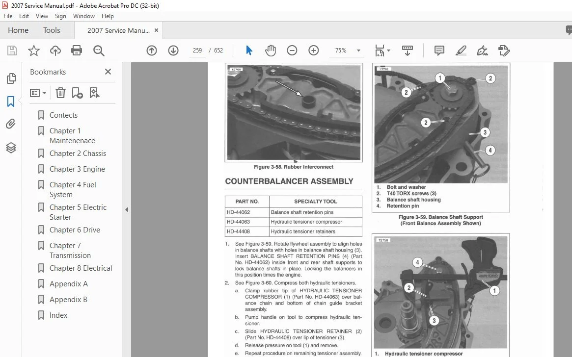
Counterbalancer AssemЫy 3-50
3 1 9 Bottom End Overhau l : AssemЫy 3-53
General 3-53
Counterbalancer AssemЫy 3-53
Balance Sprocket Spacers (tаЫе) 3-54
Crankcase 3-56
Cover and Cam Support Plate 3-60
Rear Cam Sprocket Spacers (ТаЫе) 3-62
3 20 Breather AssemЫy 3-65
Removal Overview 3-65
DisassemЫy 3-65
Cleaning and lnspection 3-65
AssemЫy 3-65
lnstallation Overview 3-65
3 21 Rocker Arm Support Plate 3-66
Removal Overview 3-66
DisassemЫy 3-66
Cleaning and lnspection 3-66
AssemЫy 3-69
lnstallation Overview 3-69
3 22 Push Rods, Lifters and Covers 3-70
Removal Overview 3-70
DisassemЫy 3-70
Cleaning and lnspection 3-70
Lifter lnspection 3-7 1
AssemЫy 3-72
lnstallation Overview 3-72
3 23 Cyli nder Head 3-73
Removal Overview 3-73
DisassemЫy 3-73
Cleaning 3-75
l nspection 3-75
Cylinder Head 3-75
Valve Guides 3-76
Valve Stem То Guide Clearance Service
Wear Limits (tаЫе) 3-76
Valves 3-76
Valve Springs 3-76
Т apered Keepers 3-76
Valve Seats 3-76
Valve Guide Replacement 3-П
Removal · 3-П
lnstallation 3-78
Valve Stem То Guide Clearance (tаЫе) 3-81
Valve and Seat Refacing 3-82
AssemЫy 3-85
lnstallation Overview 3-87
viii
Page No
3 24 Cyli nder
Removal Overview
Cleaning
l nspection
Deglazing Cylinder
Boring and Honing Cylinder
lnstallation Overview
Oversize Pistons/Cylinder Bores (tаЫе)
3 25 Piston
Removal Overview
DisassemЫy
Piston Rings
Cleaning
lnspection
AssemЫy
Piston Rings
lnstallation Overview
3 26 Cover and Cam Support Plate
Removal Overview
Camshafts
Removal
AssemЫy
Oil Pressure Relief Valve
Removal
l n stallation
Cam Needle Bearings
Removal
l nstallation
Cleaning and lnspection
Oil Pressure Valve
Cam Support Plate
lnstallation Overview
3 27 Oil Pump 3-1 07
Removal Overview 3-1 07
Cleaning and l nspection 3-1 07
l nstallation and Overview 3-1 08
3 28 Crankcase 3-1 09
Removal Overview 3-1 09
Right Crankcase Half 3- 1 09
Chain Guide Screen 3-1 09
Crankshaft Bearing 3-1 09
Piston Jets 3-1 1 О
Left Crankcase Half 3-1 1 1
Crankshaft (Roller) Bearing 3-1 1 1
Cylinder Studs 3-1 1 3
Removal 3-1 1 3
l nstallation 3-1 1 3
Pipe Plug and Oil Fittings 3-1 1 3
Removal/lnstallation 3-1 1 3
Cleaning and lnspection 3-1 1 4
lnstallation Overview 3-1 1 4
3 29 Counterbalancer AssemЫy
Removal Overview
Cleaning, lnspection and Repair
General
Balance Shaft Removal
Balance Sh aft lnstallation
Balance Shaft Support Bearings
Front and Rear Balance Sprockets
Hydraulic Т ensioners
Chain Tensioner Guides
Chain Guide Bracket
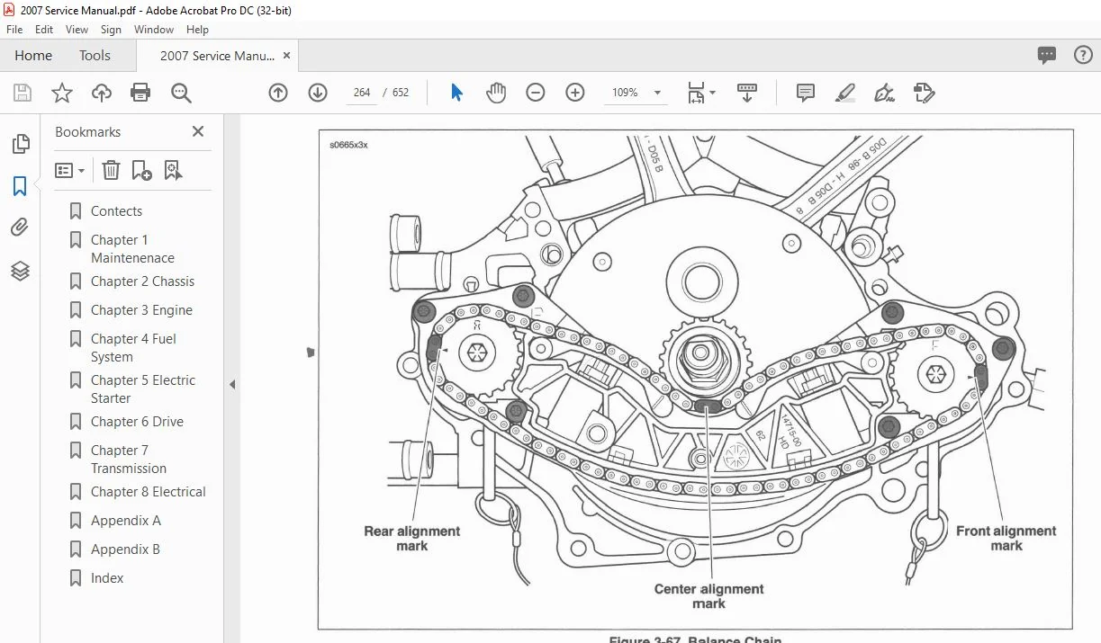
Balance Chain
lnstallation Overview
3 30 FlywheeVConnecting Rod 3-119
Removal Overview 3-119
lnspection 3-119
lnstallation Overview 3-119
3 31 Oil Tank 3-120
Page No
4 8 Engine Temperature Sensor ( ЕТ) 4-16
General
Removal
lnstallation
4 9 lnduction Module
Removal
lnstallation
4 1 О ldle Air Control (IAC)
General
Removal
lnstallation
4 11 Manifold Absolute Pressure Sensor
( МАР) 4-22
General 4 -22
Removal 4 -22
lnstallation 4 – 22
Removal/Di sassemЫy 3-120 4 12 Oxygen Sensor 4-23
Oil Tank 3-120 General 4-23
Oil Line Fittings/Retainers 3-122 Removal 4-23
lnstallation 3-123 lnstallation 4-23
SECTION 4-FUEL SYSTEM
4 1 Specifications 4-1
Torque Values (tаЫе) 4-1
4 2 Electronic Fuel lnjection ( EFI)
System 4-3
General 4-3
TrouЫeshooting 4-3
4 3 ldle Speed 4-5
General 4-5
4 4 Air Cleaner 4-6
Removal 4 -6
lnstallation 4 -6
Backplate AssemЫy: HD I Models 4-7
4 5 Fuel Tank 4-8
General 4-8
Removal 4-8
Cleaning and lnspection 4-12
lnstallation 4-12
AII But FXSTD I 4-12
4 6 Throttle Position Sensor (ТР) 4-14
General 4-14
Removal 4-14
lnstallation 4-14
4 7 lntake Air Temperature Sensor
(IАТ) 4-1 5
General 4 -15
Removal 4-15
lnstallation 4 -15
4 13 Fuel lnjectors 4-25
General 4-25
Removal 4-25
lnstallation 4 -26
4 14 Fuel· Pump/Fuel Gauge
Sending Unit 4-27
General 4-27
Removal 4-27
D i sassemЫy/AssemЬly 4 -30
lnstallation 4 – 34
4 15 Fuel Pressure Test 4-35
General 4-35
Testing 4 -35
4 16 Exhaust System: FXST/FLSTC/
FXSTB/FXSTC 4-38
Mufflers 4 -38
Removal 4 -38
AssemЫ y 4 -38
System 4-38
Removal 4 -38
lnstallation 4- 39
4 17 Exhaust System: FXSTD/FLSTF 4-41
Mufflers 4-41
Removal 4-41
AssemЫy 4-41
System 4-42
Removal 4-42
lnstallation 4 -4 2
4 18 Exhaust System : FLSTN 4-44
Mufflers 4 -4 4
Removal 4-44
AssemЫy 4-44
System 4-45
Removal 4 -4 5
lnstallation 4-45
i x
Page No
4 1 9 Exhaust System : FLSTSC 4-47
Removal 4-47
l n stallation 4-48
4 20 l ntake Leak Test 4-50
General 4-50
Leak Tester 4-50
Parts List 4-50
Tester AssemЫy 4-50
Tester Adj ustment 4-50
P rocedu re 4-5 1
4 21 Evaporative E m i ssions Control : СА
Models 4-52
General 4-52
Charcoal Canister 4-53
Removal 4-53
lnstal l ation 4-53
Hose Routi ng/Replacement 4-54
S ECTI O N 5-E LECT R I C ST ART E R
5 1 Specifications 5-1
Torque Values 5-1
5 2 Electric Starter System 5-2
General 5-2
Starter Relay 5-2
Operation 5-2
5 3 Starter Relay 5-5
Removal 5-5
l nsta l l ation 5-5
5 4 Starter 5-6
Removal 5-6
lnstallation 5-6
Disassem Ыy, l nspection and Repa i r 5-7
AssemЫy 5- 1 0
5 5 Starter Solenoid 5-1 2
General 5- 1 2
DisassemЫy 5-1 2
AssemЫy 5-1 2
SECTI O N 6-D R I V E
6 1 Specifications 6-1
Torque Val ues (ТаЫе) 6-1
6 2 Primary Chaincase 6-2
General 6-2
Primary Chai ncase Cover 6-2
Removal 6-2
l nstallation 6-3
Primary Chaincase Housing 6-4
Removal · 6-4
l n spection 6-4
l n stal lation 6-4
Mainshaft Bearing апd Lip Seal 6-6
Removal 6-6
Shifter S haft Bushing 6-7
х
Page No
6 3 Drive Com ponents 6-8
Primary Chain and Compensating Sprocket 6-8
Removal 6-8
l n stal lation 6- 1 0
6 4 C l utch 6-1 4
Removal/lnsta l l ation
Cl utch Pack Опlу
Partial DisassemЫy
AssemЫy
Cleaning and l nspection
Clutch Pack and Beari ng
Com p l ete DisassemЫy
AssemЫy
6 5 Transmission Sprocket 6-20
Removal 6-20
Cleaning and l nspection 6-2 1
lnstal lation 6-2 1
6 6 Drive Belt 6-23
Removal 6-23
l n spection 6-23
l nsta l l ation 6-24
SECTI O N 7-TRANSM I SS I O N
7 1 Specifications
Torque Values
7 2 Transm ission
General
Neutral
1 st Gear
2nd Gear
3 rd Gear
4th Gear
5th Gear
6th Gear
Shifter Linkage Adjustment
7 3 Sh ifter Forks
Cleaning and l nspection
7 4 Transmission C l utch Release
Cover
Removal/DisassemЫy
Clean i n g and l nspection
Assem Ыy/l nstallation
7 5 Transm ission AssemЫy
Removal
DisassemЫy
Countershaft
Clean i n g апd l nspection
Replacing Side Door Beari ngs
AssemЫy
l nstallation
7 6 Main Drive Gear And Bearing 7-24
Removal 7-24
Cleaning and l nspection 7-26
N eed le Bearing Replacement 7-27
l n stal l ation 7-30
l nstal l i ng Main Drive Gear 7-3 1
l nsta l l i n g Маiп Drive Gear Seal 7-32
7 7 Transmission Case 7-34
Removal 7-34
General 7-34
DisassemЫy 7-34
S hifter Arm AssemЫy 7-34
C leani ng and l nspection 7-36
AssemЫy 7-37
Cou ntershaft Needle Bearing Replacement 7-37
S h ifte r Pawl Lever AssemЫy 7-37
SECTION 8-ELECTRICAL
8 1 Specifications
Torque Values (tаЫе)
8 2 Bulb Requirements
General
Softai l B u l b Chart (tаЫе)
8 3 Electrical Panel
General
Removal
l n stal l ation
8 4 Electronic Control Module ( ЕСМ)
General 8-6
Removal 8-6
l nstallation 8-7
8 5 Crank Position Sensor (СКР) 8-8
General 8-8
Removal 8-8
l n stal l ation 8-9
8 6 Spark Plug СаЫеs 8-1 О
General 8-1 О
Removal 8-1 О
l nspection 8-1 1
l nstallation 8-1 1
8 7 lgnition Coil 8-12
Removal 8- 1 2
lnstal lation 8-1 2
8 8 Fuses 8-13
General 8- 1 3
Removal 8-1 3
l nstallation 8- 1 3
8 9 Relays 8-14
General : 8- 1 4
Removal 8- 1 4
lnstal lation 8- 1 4
Page N o
8 10 Main Fuse 8-15
Removal 8 – 1 5
l n stal lation 8 – 1 5
8 11 lgnition/Light Switch 8-16
General 8-1 6
Replacement 8-1 6
Кеу Switch Functions and Positions (tаЫе) 8 – 1 6
8 12 Alternator 8-17
Removal/DisassemЫy 8-1 7
Cleaning/l nspection 8 – 1 7
AssemЫy/l nsta l l ation 8- 1 7
8 13 Voltage Regulator 8-18
General 8-1 8
8 14 Front Electrical Caddy 8-20
General
DisassemЫy
AssemЫy
8-20
8-20
8-22
8 15 Battery 8-24
Battery Т esting 8-24
General 8-24
Voltmeter Test 8-24
Voltmeter Test For Battery C harge Conditions (tаЫе) 8-24
Conductance Test 8-24
Load Test 8-25
Battery Load Test (tаЫе) 8-25
Charg i n g Battery 8-26
Safety Precautions 8-26
Using а Battery Charger 8-26
Battery Charg i n g Rates/Тimes (Approximate) (tаЫе) 8-26
8 16 Battery СаЫеs 8-28
Routing Procedu re 8-28
8 17 Headlamp 8-30
General 8-30
Removal/l n sta l l ation 8-30
FXSTD, FXSTS and FLSTSC Models 8-30
FXST and FXSTB Models 8-3 1
FLSTC , FLSTF and FLSTN Models 8-3 1
8 18 Tail Lamp: AI I But FXSTD/
FLSTSC/FLSTN 8-33
General 8-33
B u l b Replacement 8-33
Base Replacement 8-33
Tail Lamp Wi res (tаЫе) 8-34
8 19 Tail Lamp: FXSTD 8-35
Removal 8-35
l n stallation 8-36
8 20 Tail Lamp: FLSTSC/FLSTN 8-37
Bulb Replacement 8-37
Tai l Lam p Replacement 8-37
xi
8 21 Auxiliary Lamps : FLSTC/FLSTN 8-39 8 30 lnd icator Lamps: AII But FXSTD 8-60
Auxiliary Lamp Bulb
Removal
lnstallation
FLSTC Models
Auxiliary Lamp Bracket Removal
Auxiliary Lamp Bracket lnstallation
Auxiliary Lamp Housing Removal
Auxiliary Lamp Housing lnstallation
FLSTN Models
Auxiliary Lamp Bracket Removal
Auxiliary Lamp Bracket lnstallation
Auxiliary Lamp Housing Removal
Auxiliary Lamp Housing lnstallation
Adjustment: FLSTC/FLSTN Models
8 22 Front Fender Lam p : FLSTSC 8-46
Removal 8-46
lnstallation 8-46
8 23 Turn Signals/Running Lights 8-47
Bulb Replacement: AII But FLSTC 8-47
Bulb Replacement: FLSTC 8-47
Lamp Replacement 8-47
Front Turn Signals: AII But FLSTC, FLSTN, FLSTSC,
FXSTS 8-48
Front Turn Signals: FLSTSC, FXSTC 8-49
Rear Turn Signals: AII But FXSTD, FLSTSC, FLSTN 8-50
Rear Turn Signals: FXSTD 8-50
Rear Turn Signals: FLSTSC 8-51
Rear Turn Signals: FLSTN 8-51
8 24 TSМ/Т’SSМ/НFSM 8-52
General 8-52
Removal 8-52
lnstallation 8-52
TSM/ТSSM Configuration 8-53
8 25 Fuel Gauge 8-54
General 8-54
Removal 8-54
lnstallation 8-55
8 26 lnstrument Console: FXSTD 8-56
Removal 8-56
l nstallation 8-56
8 27 Speedometer: AII But FXSTD 8-57
Removal 8-57
lnstallation 8-57
8 28 Speedometer: FXSTD 8-58
Removal 8-58
lnstallation 8-58
8 29 Vehicle Speed Sensor: VSS 8-59
General 8-S9
Removal 8-59
lnstallation 8-59
General 8-60
Removal 8-60
lnstallation 8-60
Connector (2 1 ] Pins (tаЫе) 8-60
lndicator Lamp AssemЫy Wiring (tаЫе) 8-60
8 31 lndicator Lamps: FXSTD 8-61
General 8-61
Removal 8-61
lnstallation 8-61
8 32 Neutral Switch 8-62
General 8-62
Removal 8-62
lnstallation 8-62
8 33 Oil Pressure Switch 8-63
General 8-63
Removal 8-63
lnstallation 8-63
8 34 Rear Stop Light Switch 8-64
General 8-64
Removal 8-64
lnstallation 8-64
8 35 Horn 8-65
lnspection 8-65
RepJacement 8-65
8 36 Active Exhaust Module 8-66
General 8-66
Removal 8-66
Repair 8-67
lnstallation 8-67
8 37 Main Wiring Harness 8-68
Removal 8-68
lnstallation 8-70
8 38 Hand lebar Switch AssemЫies ” 8-72
General 8-72
Repair Procedures 8-72
8 39 Right Handlebar Switch 8-73
Removal 8-73
lnstallation 8-73
DisassemЫy 8-75
Switch Repair/Replacement 8-76
Upper Housing Repair 8-76
Lower Housing Repair 8-77
AssemЫy 8-78
8 40 Left Handlebar Switch 8-79
Removal 8-79
l nstallation 8-79
DisassemЫy 8-80
Switch Repair/Replacement 8-80
Upper Housing Repair 8-80
Lower Housing Repair 8-82
AssemЫy 8-83
APPENDIX А-TOOLS
А 1 Tools
AP PENDIX B-WIRING
В 1 Amp 1-Place Connector
Pin and Socket Housings
То Separate Housings
То Mate Hou sings
Wire Terminals
Remove Socket Termin al s
lnstal l Socket Terminal
Remove Pin Terminal s
l nstal l Pin Terminal s
В 2 Amp Multilock
Pin and Socket Housings
Separate Housings
Mate Housings
Wire Terminals
Remove Terminals from Housing
lnsert Terminals into Housings
Terminal Crimps
Prepare Wire Leads
Crimp Terminals to Leads
lnspect Crimp
В З Delphi Connectors
Pin and Socket Housings
То Separate Housings
То Mate Housings
Wire Terminals
Remove Socket Terminals
l n stall Socket Terminal s
Housing
То Separate Housings
То Mate Housings
Wire Terminals
Remove Terminal
lnstallation
В 5 Deutsch
Pin an d Socket Housings
Separate Housings
Mate Housings
Wire Terminals
Remove Socket Terminal s
lnstal l Socket Terminal s
Remove Pin Terminal s
install Pin Terminals
Terminal Crimps
В 6 Standard Deutsch Terminal
Crimps
Terminal Crimps
Prepare Wire Lead
Crimp Terminal to Lead
lnspect Crimp
В 7 Deutsch Mini Terminal Crimps
Terminal Crimps
Prepare Wire Lead
Crimp а Mini Terminal to а Wire Lead
l nspect Crimp
В 8 Deutsch Solid Barrel Terminal
Crimps
Wire Т erminals
Prepare Wire Lead
Adjust Crimper Tool
Crimp 8arrel Contact to Wire Lead
lnspect Crimp
В 9 Fuse Blocks
Fuse Wire Leads
Remove Socket Terminals
lnstal l Socket Terminals
Terminal Crimps
В 10 150 Metri- Pack
P in an d Socket Housings
Wire Termin al s
Remove Terminals
lnsert Terminals
Termin al Crimps
В 11 280 Metri- Pack
P in and Socket Housings
То Separate Housings
То Mate Housings
Wire Termin al s
Remove Socket Terminals
lnstall Socket Terminals
Termin al Crimps
В 12 480 Metri- Pack
P in and Socket Housings
То Separate Housings
То Mate Housings
Wire Terminals
Remove Socket Terminal
l nstal l Socket Terminal
В 1 З 630 Metri-Pack
Pin and Socket Housings
Separate Housings
Mate Housings
Wire Terminals
Remove Socket Termin al s
ln stall Socket Terminal s
В 14 800 Metri-Pack
Fuse an d Socket Housing
Remove the Maxi-Fuse
lnstall Maxi-Fu se
Wire Terminals
Remove Socket Terminals
lnstall Socket Т erminals
Terminal Crimps
8 15 Metri- Pack Terminal Crimps 8-30
Match Terminal to Crimper 8-30
Terminal C r i m ps 8-3 1
P repare Wire Lead 8-3 1
Crimp Wi re Саге 8-3 1
Crimp l ns u l ation/Seal 8-3 1
l nspect Crimp 8-31
8 16 Packard 1 00W 8-32
Socket Housing 8-32
Separate Socket Housing from ЕСМ 8-32
Mate Socket Housing to ЕСМ 8-32
Wire Terminals 8-32
Remove Socket Term inals 8-32
l nstall Socket Term inals 8-32
В 17 Molex 8-34
Pin and Socket Housings 8-34
Separate the Housings 8-34
Mate the Housings 8-34
Wire Term i nals 8-34
Remove Termi nals 8-34
l nstall Term i n al 8-35
8 18 Packard Micro 64 8-36
Pin and Socket Housings 8-36
Separate the Housings 8-36
M ate the Housings 8-36
Wire Term inals 8-36
Remove Term inals 8-36
l nsta l l Term inals 8-37
Terminal Crimps 8-38
Prepare Wire Lead 8-38
Crimp Term i n a l 8-38
l nspect Crimp 8-38
8 19 Sealed Splice 8-39
P repare W i re Leads 8-39
Splicing Wire Leads 8-40
l nspect Seal 8-40
8 20 Connector Locations В-41
8 21 lndex to Wiring Diagrams 8-43
Wire Color Codes 8-43
Wiring D i ag ram Symbols 8-43
AP PENDIX C-METRIC
CONVER SIONS
С 1 Metric Conversions С-1
С 2 Fluid Conversions С-2
U n ited States Syste m С-2
Metric System С-2
8ritish l m perial System С-2
APPENDIX D-G LOSSARY
D 1 Glossary D-I
2007 HARLEY DAVIDSON SOFTAIL MODELS SERVICE MANUAL – PDF DOWNLOAD:
PLEASE NOTE:
- This is the SAME manual used by the dealers to troubleshoot any faults in your vehicle. This can be yours in 2 minutes after the payment is made.
- Contact us at [email protected] should you have any queries before your purchase or that you need any other service / repair / parts operators manual.
S.V