2008 Dodge Ram Parts Manual – PDF DOWNLOAD
Original price was: $86.95.$29.95Current price is: $29.95.
2008 Dodge Ram Parts Manual – PDF DOWNLOAD
Description
2008 Dodge Ram Parts Manual – PDF DOWNLOAD
FILE DETAILS:
2008 Dodge Ram Parts Manual – PDF DOWNLOAD
Language : English
Pages : 745
Downloadable : Yes
File Type : PDF
Size: 10.7 MB
IMAGES PREVIEW OF THE MANUAL:
TABLE OF CONTENTS:
2008 Dodge Ram Parts Manual – PDF DOWNLOAD
2008DR 1
Return to Model Year Index 0
Return to 2008 Vehicle Family Index 0
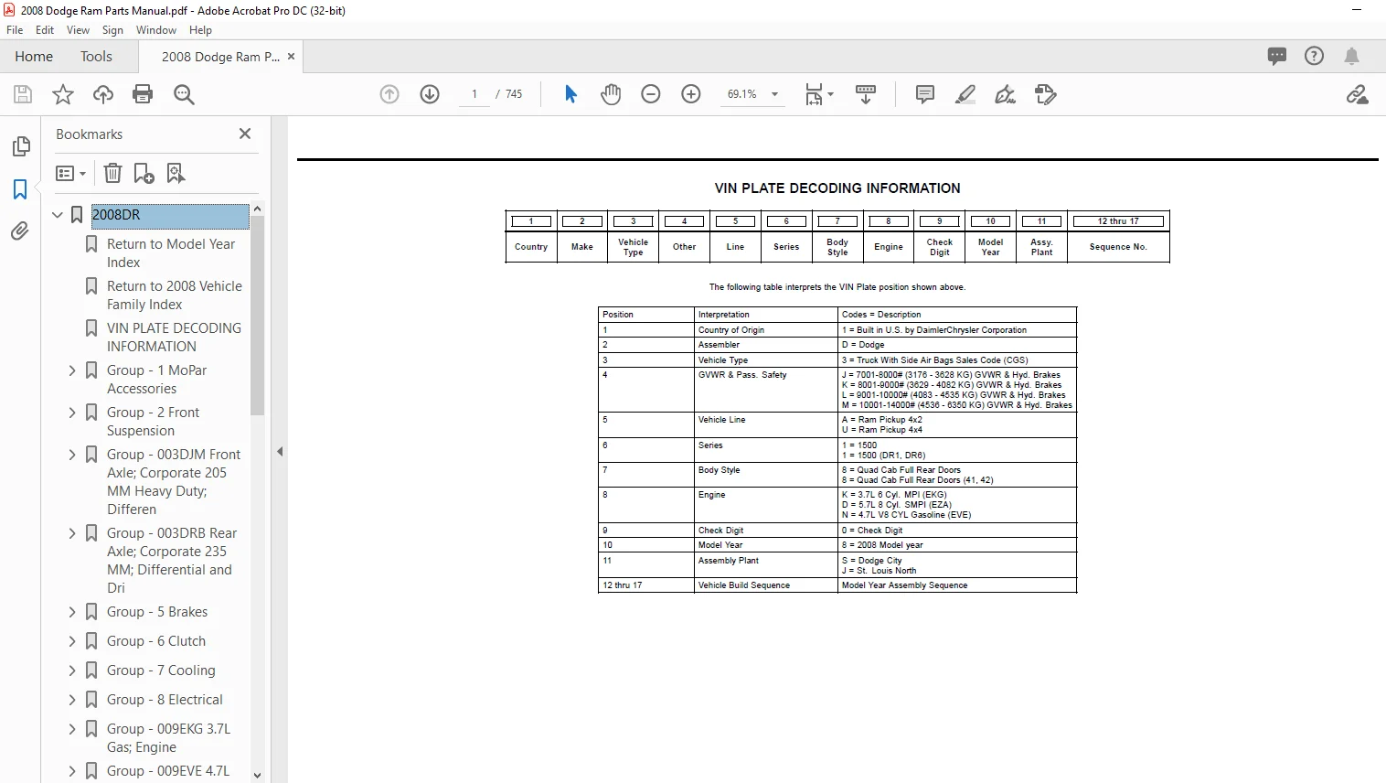
VIN PLATE DECODING INFORMATION 1
Group – 1 MoPar Accessories 2
Audio and Electronics 2
Fig 1-108 –> Navigation Kit – [REC] 3
Fig 1-109 –> Navigation Kit – Stand Alone 4
Fig 1-110 –> Media System 5
Fig 1-114 –> Install Kit – Satellite Receiver 6
Fig 1-120 –> Receiver Kit – Satellite-GEN 2 5 7
Fig 1-122 –> IPod 8
Carriers and Cargo Hauling 0
Fig 1-242 –> Wiring Package – Trailer Tow 9
Fig 1-244 –> Adapter Kit – Ball Mount 10
Fig 1-254 –> Receiver Kit – Trailer Tow 11
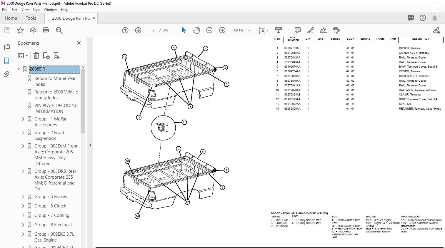
Fig 1-256 –> Cover Kit – Tonneau- Soft 12
Fig 1-260 –> Cover Kit – Tonneau – Hard 13
Driver Convenience 0
Fig 1-312 –> Hands Free Kit-Cellular Phone-Blue Tooth Low Spee 14
Fig 1-322 –> Mirror Kit 15
Exterior Appearance 0
Fig 1-412 –> Decal Kit 16
Fig 1-438 –> Board Kit – Running Power 17
Fig 1-440 –> Step Kit – Side 18
Fig 1-444 –> Spoiler Kit 20
Fig 1-448 –> Wheel Kit 21
Fig 1-452 –> Tool Box 22
Exterior Protection 0
Fig 1-502 –> Bedliner Kit – Over Rail 23
Fig 1-512 –> Liner Kit – Wheelhouse 24
Fig 1-520 –> Plate Kit – Skid – Front 25
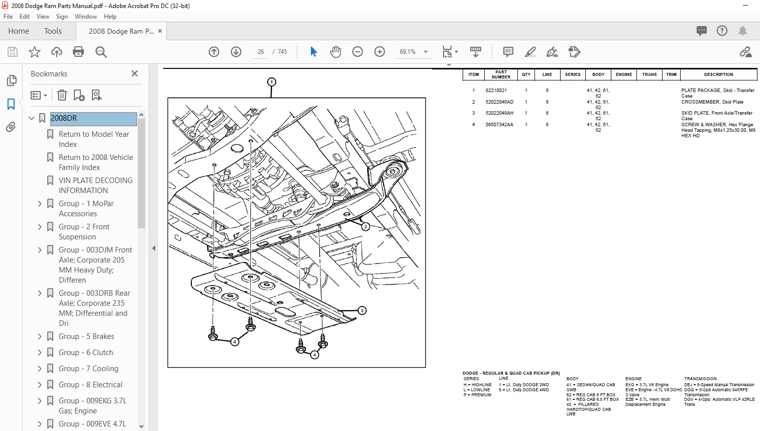
Fig 1-522 –> Plate Kit – Skid – Transfer Case 26
Fog Lights and Electrical 0
Fig 1-602 –> Heater Kit – Engine Block 5 7L 27
Fig 1-604 –> Light Kit – Fog 28
Interior Storage 0
Fig 1-806 –> Storage & Tray Kits 29
Group – 2 Front Suspension 30
Front Suspension, Strut and Cradle 30
Fig 2-110 –> Suspension, Front, DR 1 31
Fig 2-120 –> Suspension, Front, DR 6 34
Front Stabilizer Bar 0
Fig 2-210 –> Stabilizer Bar, Front 38
Group – 003DJM Front Axle; Corporate 205 MM Heavy Duty; Differen 40
Front Axle Assembly 40
Fig 003DJM-110 –> Axle Assembly, Front 41
Front Axle; Housing, Differential and Vent 0
Fig 003DJM-210 –> Housing & Vent 42
Fig 003DJM-220 –> Differential Assembly, Front 43
Front Axle Drive Shafts 0
Fig 003DJM-310 –> Shafts, Front Axle 45
Front Axle Disconnect 0
Fig 003DJM-410 –> Disconnect, Front Axle 46
Front Axle Skid Plate 0
Fig 003DJM-510 –> Skid Plate, Front Axle 47
Drive Shaft 0
Fig 003DJM-610 –> Shaft,Drive, Front 48
Group – 003DRB Rear Axle; Corporate 235 MM; Differential and Dri 49
Drive Shaft 49
Fig 003DRB-610 –> Shaft, Drive, Rear, 1-Piece, DR 1, DR 6 50
Fig 003DRB-620 –> Shaft, Drive, Rear, 2-Piece, DR 1, DR 6 53
Rear Axle Assembly 0
Fig 003DRB-710 –> Axle Assembly, Rear, DR 1, DR 6 57
Rear Axle; Housing, Differential and Vent 0
Fig 003DRB-810 –> Housing & Vent, DR 1, DR 6 58
Fig 003DRB-820 –> Differential Assembly, DR 1, DR 6 60
Rear Axle Shafts 0
Fig 003DRB-910 –> Shafts, Rear, Axle,DR 1, DR 6 66
Group – 5 Brakes 67
Front Brakes 67
Fig 5-110 –> Brakes,Front 68
Rear Brakes 0
Fig 5-210 –> Brakes,Rear,Disc 70
Power Brake Booster 0
Fig 5-310 –> Booster,Vacuum Power Brake 73
Brake Master Cylinder 0
Fig 5-410 –> Master Cylinder,Brake 74
Hydraulic Control Unit, Brake Tubes and Hoses 0
Fig 5-516 –> HCU,Brake Tubes and Hoses,Front,[BRT],A W A L 75
Fig 5-520 –> Brake Tubes and Hoses,Rear and Chassis,[BRR],R W 78
Fig 5-521 –> Brake Tubes and Hoses,Rear and Chassis,[BNB,BRT], 80
Brake Pedals 0
Fig 5-610 –> Pedal,Brake,Standard,[XA8] 82
Fig 5-620 –> Pedal,Brake,Power Adjustable,[XAP] 83
Parking Brake Lever, Cables, and Rear Disc Park Brake Assembly 0
Fig 5-710 –> Park Brake Lever and Cables,Front 84
Fig 5-720 –> Park Brake Cables,Rear 85
Fig 5-730 –> Park Brake Assemby,Rear Disc 86
Group – 6 Clutch 88
Clutch 88
Fig 6-110 –> Clutch Assembly 89
Clutch Controls 0
Fig 6-310 –> Controls,Hydraulic Clutch 91
Clutch Pedals 92
Fig 6-410 –> Pedal,Clutch 93
Group – 7 Cooling 94
Radiator and Related Parts 94
Fig 7-105 –> Radiator and Related Parts 95
Fig 7-150 –> Radiator Support 98
Water Pump and Related Parts 98
Fig 7-205 –> Water Pump and Related Parts 99
Fig 7-210 –> Water Pump and Related Parts 100
Fig 7-250 –> Thermostat and Related Parts 101
Engine Coolant Reservoir (Bottle) 0
Fig 7-305 –> Coolant Recovery Bottle 102
Pulleys and Related Parts 0
Fig 7-405 –> Pulley and Related Parts Gas 103
Fig 7-410 –> Pulley and Related Parts Gas 104
Drive Belts 0
Fig 7-505 –> Belts, Serpentine and V-Belts 105
Fig 7-510 –> Drive Belts 106
Transmission Oil Cooler, and Lines 106
Fig 7-605 –> Transmission Oil Cooler and Lines 107
Group – 8 Electrical 109
Starters 110
Fig 8-105 –> Starter and Related Parts 111
Fig 8-110 –> Starter and Related Parts 112
Fig 8-115 –> Remote Start 113
Generators / Alternators 0
Fig 8-205 –> Generator/Alternator and Related Parts 114
Fig 8-210 –> Generator/Alternator and Related Parts 116
Modules and Engine Controllers 117
Fig 8-405 –> Modules Engine Compartment 118
Fig 8-410 –> Modules Instrument Panel 120
Fig 8-415 –> Modules Overhead 121
Fig 8-430 –> Modules Brakes, Suspension, and Steering 122
Power Distribution Center, Fuse Block, Junction Block, Relays an 0
Fig 8-505 –> Power Distribution Center 123
Sensors 0
Fig 8-605 –> Sensors Gas Engine 124
Fig 8-615 –> Sensors Oxygen Gas Engine 126
Fig 8-625 –> Sensors Brakes 128
Fig 8-630 –> Sensors Suspenion and Steering 129
Fig 8-635 –> Sensors Body 130
Fig 8-640 –> Sensors Powertrain 131
Switches 0
Fig 8-805 –> Switches Instrument Panel 132
Fig 8-815 –> Switches Doors 136
Fig 8-825 –> Switches Seats 137
Fig 8-830 –> Switches Steering Column and Wheel 138
Fig 8-835 –> Switches Powertrain 139
Fig 8-840 –> Switches Heating and Air Conditioning 140
Fig 8-845 –> Switches Lighting 141
Horns 141
Fig 8-905 –> Horns 142
Battery, Battery Tray and Cables 0
Fig 8-1005 –> Battery Tray and Support 143
Fig 8-1010 –> Battery Wiring 144
Lamps-Interior and Exterior 144
Fig 8-1105 –> Lamps Front 145
Fig 8-1110 –> Lamps Rear 147
Fig 8-1115 –> Lamps Courtesy 149
Wiring-Powertrain 149
Fig 8-1205 –> Wiring Engine Gas 150
Fig 8-1220 –> Ground Straps 151
Wiring-Headlamp to Dash 0
Fig 8-1305 –> Wiring Headlamp to Dash 152
Wiring-Instrument Panel 153
Fig 8-1405 –> Wiring Instrument Panel 154
Wiring-Body and Accessories 155
Fig 8-1505 –> Wiring Body 156
Fig 8-1510 –> Wiring Chassis and Underbody 158
Fig 8-1515 –> Wiring Doors 160
Fig 8-1520 –> Wiring Seats 161
Fig 8-1525 –> Wiring Air Conditioning and Heater 162
Wiring and Repair 0
Fig 8-1605 –> Wiring Repairs 163
Ignition – Spark Plugs, Cables, Coils, and Glow Plugs 163
Fig 8-1905 –> Spark Plugs, Cables, and Coils 164
Fig 8-1906 –> Spark Plugs, Cables, and Coils 165
Fig 8-1910 –> Spark Plugs, Cables, and Ignition Wires 166
Instrument Panel 166
Fig 8-2005 –> Instrument Panel and Structure 167
Fig 8-2010 –> Instrument Panel Trim 169
Instrument Panel Cluster 0
Fig 8-2105 –> Cluster Instrument Panel 174
Radio, Antenna, Speakers, DVD, and Video systems 174
Fig 8-2205 –> Radio 175
Fig 8-2210 –> Antenna 177
Fig 8-2215 –> Satellite Radio System 178
Fig 8-2220 –> Speakers and Amplifiers 179
Fig 8-2225 –> DVD and Video System 181
Consoles 181
Fig 8-2305 –> Floor Console Front [CBE] 182
Fig 8-2310 –> Floor Console Front [CAC] 183
Fig 8-2315 –> Floor Console Rear 185
Fig 8-2320 –> Overhead Console 187
Navigation 0
Fig 8-2405 –> Navigation System 189
Telecommunication 189
Fig 8-2505 –> Telecommunication System 190
Speed Control 0
Fig 8-2705 –> Speed Control 191
Group – 009EKG 3 7L Gas; Engine 192
Engine Identification 193
Fig 009EKG-105 –> Engine Assembly And Identification 3 7L[EKG] 194
Fig 009EKG-145 –> Gasket Packages 3 7L [EKG] 195
Cylinder Head 197
Fig 009EKG-205 –> Cylinder Head Covers 3 7L [EKG] 198
Fig 009EKG-225 –> Cylinder Heads 3 7L [EKG] 200
Cylinder Block 0
Fig 009EKG-305 –> Engine Cylinder Block And Hardware 3 7L[EKG] 202
Fig 009EKG-325 –> Engine Cylinder Block Heater 3 7L [EKG] 204
Crankshaft, Piston, Drive Plate, Flywheel, and Damper 0
Fig 009EKG-405 –> Crankshaft,Bearings,Damper,Flywheel3 7L[EKG] 205
Fig 009EKG-425 –> Piston, Connecting Rod, Bearings, Rings 3 7L 208
Camshaft and Valve 208
Fig 009EKG-505 –> Camshafts And Valvetrain 3 7L [EKG] 209
Timing Belt/Chain and Cover and Balance Shaft 0
Fig 009EKG-605 –> Timing Case Cover 3 7L [EKG] 212
Fig 009EKG-625 –> Timing System 3 7L [EKG] 214
Fig 009EKG-645 –> Balance Shaft 3 7L [EKG] 217
Engine Oiling, Oil Pan and Indicator (Dipstick) 0
Fig 009EKG-705 –> Engine Oil Pump 3 7L [EKG] 218
Fig 009EKG-725 –> Engine Oil Pan, Oil Level Indicator 3 7L [EK 219
Fig 009EKG-745 –> Engine Oil Filter 3 7L [EKG] 222
Manifolds and Vacuum Fittings 222
Fig 009EKG-1005 –> Exhaust Manifolds 3 7L [EKG] 223
Fig 009EKG-1025 –> Intake Manifold 3 7L [EKG] 225
Crankcase Ventilation 0
Fig 009EKG-1105 –> Crankcase Ventilation 3 7L [EKG] 227
Engine Mounting 227
Fig 009EKG-1230 –> Engine Mounting Right Side RWD/2WD 3 7L [E 228
Fig 009EKG-1250 –> Engine Mounting Left Side RWD/2WD 3 7L [EKG 229
Group – 009EVE 4 7L Gas; Engine 230
Engine Identification 231
Fig 009EVE-105 –> Engine Assembly And Identification 4 7L[EVE] 232
Fig 009EVE-145 –> Engine Gasket Packages 4 7L [EVE] 233
Cylinder Head 235
Fig 009EVE-205 –> Cylinder Head Covers 4 7L [EVE] 236
Fig 009EVE-225 –> Cylinder Heads 4 7L [EVE] 238
Cylinder Block 0
Fig 009EVE-305 –> Engine Cylinder Block And Hardware 4 7L [EVE 241
Fig 009EVE-325 –> Engine Cylinder Block Heater 4 7L [EVE] 244
Crankshaft, Piston, Drive Plate, Flywheel, and Damper 0
Fig 009EVE-405 –> Crankshaft, Crankshaft Bearings, Damper, Fly 245
Fig 009EVE-425 –> Pistons, Connecting Rods, Connecting Rod Bea 248
Camshaft and Valve 248
Fig 009EVE-505 –> Camshafts And Valvetrain 4 7L [EVE] 249
Timing Belt/Chain and Cover and Balance Shaft 0
Fig 009EVE-605 –> Timing Case Cover 4 7L [EVE] 251
Fig 009EVE-625 –> Timing System 4 7L [EVE] 253
Engine Oiling, Oil Pan and Indicator (Dipstick) 0
Fig 009EVE-705 –> Engine Oiling Pump 4 7L [EVE] 256
Fig 009EVE-725 –> Engine Oil Pan, Engine Oil Level Indicator A 257
Fig 009EVE-745 –> Engine Oil Filter And Splash Guard 4 7L [EVE 260
Manifolds and Vacuum Fittings 260
Fig 009EVE-1005 –> Exhaust Manifold And Exhaust Manifold Heat 261
Fig 009EVE-1025 –> Intake Manifold 4 7L [EVE] 263
Crankcase Ventilation 0
Fig 009EVE-1105 –> Crankcase Ventilation 4 7L [EVE] 265
Engine Mounting 265
Fig 009EVE-1230 –> Engine Mounting Right Side RWD/2WD 4 7L [EV 266
Fig 009EVE-1235 –> Engine Mounting Right Side AWD/4WD 4 7L [EV 267
Fig 009EVE-1250 –> Engine Mounting Left Side RWD/2WD 4 7L [EVE 268
Fig 009EVE-1255 –> Engine Mounting Left Side AWD/4WD 4 7L [EVE 269
Group – 009EZB 5 7L Gas; Engine 271
Engine Identification 272
Fig 009EZB-105 –> Engine Assembly And Identification 5 7L [EZB 273
Fig 009EZB-145 –> Engine Gasket Packages 5 7L [EZB] 274
Cylinder Head 0
Fig 009EZB-205 –> Cylinder Head Covers 5 7L [EZB] 277
Fig 009EZB-225 –> Cylinder Heads 5 7L [EZB] 278
Cylinder Block 0
Fig 009EZB-305 –> Engine Cylinder Block And Hardware 5 7L [EZB 280
Fig 009EZB-325 –> Engine Cylinder Block Heater 282
Crankshaft, Piston, Drive Plate, Flywheel, and Damper 0
Fig 009EZB-405 –> Crankshaft, Crankshaft Bearings, Damper, And 283
Fig 009EZB-425 –> Pistons, Connecting Rods, Connecting Rod Bea 285
Camshaft and Valve 286
Fig 009EZB-505 –> Camshaft And Valvetrain 5 7L [EZB] 287
Timing Belt/Chain and Cover and Balance Shaft 0
Fig 009EZB-605 –> Timing Case Cover 5 7L [EZB] 290
Fig 009EZB-625 –> Timing System 5 7L [EZB] 292
Engine Oiling, Oil Pan and Indicator (Dipstick) 0
Fig 009EZB-705 –> Engine Oiling Pump 5 7L [EZB] 294
Fig 009EZB-725 –> Engine Oil Pan, Engine Oil Level Indicator A 295
Fig 009EZB-745 –> Engine Oil Filter And Splash Guard 5 7L [EZB 297
Manifolds and Vacuum Fittings 297
Fig 009EZB-1005 –> Exhaust Manifolds And Exhaust Manifold Heat 298
Fig 009EZB-1025 –> Intake Manifold 5 7L [EZB] 300
Crankcase Ventilation 301
Fig 009EZB-1105 –> Crankcase Ventilation 5 7L [EZB] 302
Engine Mounting 302
Fig 009EZB-1230 –> Engine Mounting Right Side RWD/2WD 5 7L [EZ 303
Fig 009EZB-1235 –> Engine Mounting Right Side AWD/4WD 5 7L [EZ 304
Fig 009EZB-1250 –> Engine Mounting Left Side RWD/2WD 5 7L [EZB 305
Fig 009EZB-1255 –> Engine Mounting Left Side AWD/4WD 5 7L [EZB 306
Group – 10 Restraints 308
Air Bags 308
Fig 10-205 –> Air Bag Modules, Sensors, and Clockspring 309
Fig 10-210 –> Air Bags Front 311
Fig 10-215 –> Air Bags Side 312
Seat Belts 312
Fig 10-325 –> Seat Belts – Regular Cab 313
Fig 10-330 –> Seat Belts – Quad Cab 318
Group – 11 Exhaust 325
Exhaust System 325
Fig 11-105 –> Exhaust System 3 7L [EK0] 326
Fig 11-110 –> Exhaust System 4 7L [EV0] 327
Fig 11-115 –> Exhaust System 5 7L [EZ0] 328
Group – 13 Frame, Bumper, and Fascia 330
Frames 330
Fig 13-105 –> Frame, Complete 331
Front Bumper and Fascia 334
Fig 13-205 –> Fascia, Front, Bright 335
Fig 13-210 –> Fascia, Front, Body Color 339
Rear Bumper and Fascia 342
Fig 13-340 –> Bumper, Rear 343
Body Hold Down 345
Fig 13-405 –> Body Hold Down 346
Fig 13-410 –> Body Hold Down 347
Trailer Tow and Tow Hooks 347
Fig 13-505 –> Tow Hooks, Front 348
Fig 13-520 –> Tow Hooks and Hitches, Rear 349
Group – 14 Fuel 350
Fuel Tank 351
Fig 14-105 –> Fuel Tank and Related 352
Fuel Tank Filler Tube 0
Fig 14-205 –> Fuel Filler Tube and Related 353
Fuel Lines 353
Fig 14-305 –> Fuel Lines and Related 354
Fig 14-310 –> Fuel Lines Chassis 355
Fuel Rail and Injectors 356
Fig 14-405 –> Fuel Rail 357
Fuel Pump and Sending Unit 0
Fig 14-505 –> Fuel Pump Module 359
Throttle Body 359
Fig 14-605 –> Throttle Body and Related 360
Throttle Controls 360
Fig 14-705 –> Throttle Controls and Related 361
Air Cleaner 0
Fig 14-805 –> Air Cleaner and Related 362
Air Inlet Components 0
Fig 14-905 –> Air Inlet and Components 366
Accelerator Pedal 366
Fig 14-1005 –> Accelerator Pedal Power Adjustable 367
Fig 14-1010 –> Accelerator Pedal and Related 368
Group – 17 Rear Suspension 369
Rear Suspension and Cradle 369
Fig 17-110 –> Suspension,Rear 370
Group – 19 Steering 373
Steering Wheel 373
Fig 19-105 –> Steering Wheel Assembly 374
Steering Column and Intermediate Shaft 0
Fig 19-205 –> Steering Column Assembly 378
Steering Gear 380
Fig 19-305 –> Steering Gear – Left Hand Drive 381
Power Steering Pump 0
Fig 19-505 –> Pump Steering 382
Power Steering Hoses 382
Fig 19-605 –> Hoses, Power Steering 383
Group – 021DEJ G238; 6-Speed; Manual Transmission 384
Manual Transmission / Transaxle 384
Fig 021DEJ-105 –> Transmission / Transaxle Assembly 385
Case, and Extension 385
Fig 021DEJ-205 –> Case And Related Parts 386
Fig 021DEJ-215 –> Sensors, Switches And Vents 390
Gear Train 390
Fig 021DEJ-606 –> Input Shaft Assembly 391
Fig 021DEJ-610 –> Main/Output Shaft Assembly 392
Fig 021DEJ-615 –> Counter Shaft Assembly 394
Fig 021DEJ-620 –> Reverse Idler Shaft Assembly 396
Fork and Rails 396
Fig 021DEJ-1006 –> Shift Forks And Rails 397
Gearshift Controls and Related Parts 398
Fig 021DEJ-1105 –> Gear Shift Lever 399
Fig 021DEJ-1110 –> Gear Shift Boot, Knob and Bezel 400
Mounting and Skid Plate 400
Fig 021DEJ-1210 –> Structural Collar 401
Fig 021DEJ-1215 –> Mounting Bolts 402
Group – 021DGQ 545RFE; 5-Speed; Automatic Transmission 403
Automatic Transmission / Transaxle and Torque Converter 404
Fig 021DGQ-105 –> Transmission / Transaxle Assembly 405
Fig 021DGQ-110 –> Torque Converter 406
Case, Extension, Oil Pan, and Indicator (Dipstick) 406
Fig 021DGQ-205 –> Case 407
Fig 021DGQ-220 –> Extensions And Adapters 408
Fig 021DGQ-225 –> Oil Fill Tube And Related Parts 409
Fig 021DGQ-230 –> Oil Pan, Cover And Related Parts 410
Fig 021DGQ-235 –> Filters 411
Fig 021DGQ-240 –> Sensors, Vents And Quick Connectors 412
Seal and Shim Packages 412
Fig 021DGQ-305 –> Seal and Shim Packages 413
Oil Pump 414
Fig 021DGQ-415 –> Oil Pump and Related Parts 415
Clutches 415
Fig 021DGQ-521 –> Input Clutch Assembly 416
Fig 021DGQ-522 –> Input Clutch Assembly 419
Fig 021DGQ-523 –> Input Clutch Assembly 420
Fig 021DGQ-524 –> 2C / 4C Clutch 421
Fig 021DGQ-525 –> Low / Reverse Clutch 423
Gear Train 0
Fig 021DGQ-609 –> Reaction Planetary 425
Fig 021DGQ-610 –> Input / Reverse Planetary 426
Valve Body, Accumulator, Solenoid and Parking Sprag 427
Fig 021DGQ-820 –> Valve Body And Related Parts 428
Fig 021DGQ-860 –> Parking Sprag And Related Parts 430
Gearshift Controls and Related Parts 431
Fig 021DGQ-1115 –> Gearshift Lever, Cable and Bracket 432
Mounting and Skid Plate 0
Fig 021DGQ-1210 –> Structural Collar 433
Fig 021DGQ-1215 –> Mounting Bolts 434
Group – 021DGV 42RLE; 4-Speed; Automatic Transmission 435
Automatic Transmission / Transaxle and Torque Converter 435
Fig 021DGV-105 –> Transmission / Transaxle Assembly 436
Fig 021DGV-110 –> Torque Converter 437
Case, Extension, Oil Pan, and Indicator (Dipstick) 0
Fig 021DGV-205 –> Case 438
Fig 021DGV-220 –> Extensions And Adapters 439
Fig 021DGV-225 –> Oil Fill Tube And Related Parts 440
Fig 021DGV-230 –> Oil Pan, Cover And Related Parts 441
Fig 021DGV-235 –> Filters 442
Fig 021DGV-240 –> Sensors, Vents And Quick Connectors 443
Oil Pump 0
Fig 021DGV-405 –> Oil Pump and Related Parts 444
Clutches 0
Fig 021DGV-514 –> Input Clutch Assembly 445
Fig 021DGV-515 –> Input Clutch Assembly 446
Fig 021DGV-516 –> Input Clutch Assembly 447
Fig 021DGV-517 –> Input Clutch Assembly 448
Fig 021DGV-518 –> Input Clutch Assembly 449
Fig 021DGV-519 –> 2 / 4 Clutch 450
Fig 021DGV-520 –> Low / Reverse Clutch 451
Gear Train 0
Fig 021DGV-608 –> Front / Rear Planetary 452
Valve Body, Accumulator, Solenoid and Parking Sprag 0
Fig 021DGV-805 –> Valve Body And Related Parts 454
Fig 021DGV-850 –> Accumulator And Related Parts 455
Fig 021DGV-860 –> Parking Sprag And Related Parts 456
Gearshift Controls and Related Parts 0
Fig 021DGV-1115 –> Gearshift Lever, Cable and Bracket 457
Mounting and Skid Plate 0
Fig 021DGV-1210 –> Structural Collar 458
Fig 021DGV-1215 –> Mounting Bolts 459
Group – 021DH5 NV243; Transfer Case 460
Transfer Case Assembly 460
Fig 021DH5-105 –> Transfer Case Assembly And Identification NV 461
Case, and Extension 0
Fig 021DH5-205 –> Case Front Half NV 243 [DH5] 462
Fig 021DH5-210 –> Case Rear Half NV 243 [DH5] 464
Oil Pump 0
Fig 021DH5-405 –> Oil Pump NV 243 [DH5] 466
Gear Train 0
Fig 021DH5-605 –> Gear Train NV 243 [DH5] 468
Fork and Rails 0
Fig 021DH5-1005 –> Forks And Rails NV 243 [DH5] 470
Gearshift Controls and Related Parts 0
Fig 021DH5-1110 –> Gear Shift Switch, Motor And Actuator NV243 471
Mounting and Skid Plate 471
Fig 021DH5-1205 –> Transfer Case Mounting And Venting NV 243 [ 472
Fig 021DH5-1210 –> Transfer Case Skid Plate NV 243 [DH5] 473
Group – 021DH8 NV246; Transfer Case 474
Transfer Case Assembly 474
Fig 021DH8-105 –> Transfer Case Assembly And Identification NV 475
Case, and Extension 0
Fig 021DH8-205 –> Case Front Half NV 246 [DH8] 476
Fig 021DH8-210 –> Case Rear Half And Extension NV 246 [DH8] 478
Oil Pump 0
Fig 021DH8-405 –> Oil Pump NV 246 [DH8] 480
Gear Train 0
Fig 021DH8-605 –> Gear Train NV 246 [DH8] 482
Fork and Rails 0
Fig 021DH8-1005 –> Forks And Rails NV 246 [DH8] 484
Gearshift Controls and Related Parts 0
Fig 021DH8-1110 –> Shift Control Switch, Gear Motor, And Actua 485
Mounting and Skid Plate 485
Fig 021DH8-1205 –> Transfer Case Mounting And Venting NV246 [D 486
Fig 021DH8-1210 –> Transfer Case Skid Plate NV246 [DH8] 487
Group – 22 Wheels 488
Wheels, Tires and Hardware 488
Fig 22-105 –> Wheels and Hardware 489
Wheel Covers and Center Caps 490
Fig 22-205 –> Wheel Covers and Center Caps 491
Jack Stowage 0
Fig 22-305 –> Jack Assembly 492
Wheel Spare 0
Fig 22-405 –> Spare Tire Stowage 493
Group – 23 Wiper/Washers-Miscellaneous 494
Lock Cylinders and Keys 494
Fig 23-105 –> Keys and Transmitters 495
Fig 23-110 –> Ignition Lock Cylinders 496
Fig 23-115 –> Door Lock Cylinders 498
Windshield Wiper and Washer System 498
Fig 23-205 –> Front Wiper System 499
Fig 23-210 –> Front Washer System 500
Group – 24 Air Conditioners and Heaters 502
Air Conditioner and Heater Units 502
Fig 24-120 –> A/C and Heater Unit [HAA] 503
Fig 24-130 –> A/C and Heater Unit Zone [HAD] 504
Air Conditioner and Heater Plumbing 0
Fig 24-205 –> Heater Plumbing 506
Fig 24-220 –> A/C Plumbing 3 7L [EK0] 4 7L [EV0] 507
Fig 24-230 –> A/C Plumbing 5 7L [EZ0] 510
Fig 24-240 –> Air Conditioning Condenser and Fan 512
Air Conditioner and Heater Controls 0
Fig 24-310 –> A/C and Heater Controls 513
Air Conditioner Compressor and Mounting 0
Fig 24-405 –> A/C Compressor 514
Fig 24-450 –> A/C Compressor Mounting 3 7L [EKG] 4 7L [EVE] 516
Fig 24-460 –> A/C Compressor Mounting 5 7L 517
Air Ducts and Outlets 517
Fig 24-505 –> Ducts and Outlets Front 518
Group – 25 Emission Controls 520
EGR System 520
Fig 25-205 –> EGR Valve and Related 521
Vacuum Canister/Leak Detection Pump 0
Fig 25-305 –> Vapor Canister and Leak Detection Pump 523
Emission Harness 0
Fig 25-405 –> Emission Control Vacuum Harness 525
Fig 25-410 –> Emission Control Vacuum Harness 5 7L [EZ0] 526
Group – 26 Labels 527
Interior 527
Fig 26-105 –> Instrument Panel 528
Fig 26-110 –> Visor 529
Under Hood 0
Fig 26-205 –> Core Support 530
Doors 0
Fig 26-305 –> Doors 531
Fig 26-315 –> Fuel Door 532
Trunk 0
Fig 26-510 –> Spare Tire 533
Group – 27 Glass 534
Glass and Interior Rear View Mirror 534
Fig 27-105 –> Glass, Glass Hardware & Interior Mirrors 535
Group – 30 Doors, Door Mirrors and Related Parts 539
Front Door 539
Fig 30-105 –> Front Door, Shell and Hinges 540
Fig 30-125 –> Front Door, Hardware Components 542
Rear Door 0
Fig 30-205 –> Rear Door, Shell and Hinges 548
Fig 30-225 –> Rear Door, Hardware Components 550
Exterior Mirror 553
Fig 30-505 –> Mirror, Exterior 554
Weatherstrips and Seals 0
Fig 30-605 –> Weatherstrips, Front Door, Standard Cab 557
Fig 30-610 –> Weatherstrips, Front Door, Quad Cab 559
Fig 30-630 –> Weatherstrips, Rear Door 561
Lift and Tail Gates 0
Fig 30-705 –> Tailgate 563
Group – 40 Exterior Ornamentation 566
Nameplates 566
Fig 40-105 –> Nameplates, Emblems & Medallions 567
Moldings and Ornamentation 568
Fig 40-210 –> Exterior Ornamentation 569
Fig 40-245 –> Spoilers 571
Decals, Medallions and Tape Strips 571
Fig 40-305 –> Decals & Tape Stripes 572
Grilles 0
Fig 40-405 –> Grilles 573
Group – 50 Interior Trim 575
Headliners-Visors-Assist Straps 575
Fig 50-105 –> Headliners and Visors 576
Panels-Moldings-Scuff Plates, Pillar, Cowl, 1/4 Panel Trim and C 0
Fig 50-205 –> Interior Moldings and Pillars 581
Fig 50-225 –> Cowl Side Panel and Scuff Plates 584
Fig 50-240 –> Rear Cab Trim Panel 585
Carpets, Floor Mats, Load Floor, and Silencers 0
Fig 50-305 –> Carpet, Complete 586
Fig 50-385 –> Silencers 588
Door Trim Panels-Front and Rear 589
Fig 50-405 –> Front Door Trim Panels 590
Fig 50-415 –> Rear Door Trim Panels 627
Front Seats – First Row 0
Fig 50-502 –> Front Seat – Bucket – Trim Code [AJ] 633
Fig 50-504 –> Front Seat – Bucket – Trim Code [CJ] 637
Fig 50-506 –> Front Seat – Bucket – Trim Code [GJ] 640
Fig 50-580 –> Front Seat – 40/20/40 – Trim Code [TX] 645
Fig 50-582 –> Front Seat – 40/20/40 – Trim Code [P9] 650
Fig 50-584 –> Front Seat – 40/20/40 – Trim Code [V9] 655
Fig 50-586 –> Front Seat – 40/20/40 – Trim Code [M9] 660
Fig 50-588 –> Front Seat – 40/20/40 – Trim Code [VL] 667
Rear Seats – Second Row 672
Fig 50-620 –> Rear Seat – Bench – Trim Code [TX] 673
Fig 50-625 –> Rear Seat – Bench – Trim Code [P9] 674
Fig 50-630 –> Rear Seat – Bench – Trim Code [V9] 676
Fig 50-635 –> Rear Seat – 60/40 – Trim Code [M9] 678
Fig 50-640 –> Rear Seat – 60/40- Trim Code [VL] 682
Fig 50-645 –> Rear Seat – 60/40 – Trim Code [AJ] 685
Fig 50-650 –> Rear Seat – 60/40 – Trim Code [CJ] 688
Fig 50-655 –> Rear Seat – 60/40 – Trim Code [GJ] 690
Front Seats – Adjusters, Recliners, Shields and Risers 692
Fig 50-925 –> Risers- Miscellaneous Front Seat Attachments 693
Rear Storage Compartment 706
Fig 50-1305 –> Rear Storage Compartment 707
Group – 60 Body Sheet Metal Except Doors 708
Floor Pans 709
Fig 60-105 –> Front Floor Pan 710
Fig 60-130 –> Center and Rear Floor pan 712
Plugs 0
Fig 60-230 –> Floor Pan Plugs 713
Fig 60-250 –> Pick-Up Box Plugs 714
Fig 60-275 –> Hood, Doors, Decklid, Tailgate, & Liftgate Plugs 715
Fenders 715
Fig 60-305 –> Front Fender 716
Hood and Hood Release 0
Fig 60-405 –> Hood and Related Parts 718
Cowl and Dash Panel 0
Fig 60-505 –> Cowl,Dash Panel, & Related Parts 720
Aperture Panel, Pillar Supports and Cab Back 721
Fig 60-610 –> Front Aperture Panel 2-Door 722
Fig 60-615 –> Front Aperture Panel 4-Door 725
Fig 60-625 –> Cab Back 728
Fig 60-655 –> Rear Wheelhouse Shields 730
Pick-up Box and Fuel Filler Door 730
Fig 60-705 –> Tailgate 731
Fig 60-710 –> Pick-up Box 733
Fig 60-740 –> Pick-up Box Crossmembers, Reinforcements 737
Fig 60-775 –> Fuel Filler Housing and Door 739
Body Structure Welds, Weatherstrips, Seals, Sealers and Adhesive 739
Fig 60-805 –> Body Weatherstrips and Seals 740
Roof 0
Fig 60-905 –> Roof Panel 742
Sunroof 742
Fig 60-1005 –> Sunroof Glass and Component Parts 743
Fig 60-1050 –> Sunfoof Drain Hoses 745
Contact us: [email protected]
https://vimeo.com/765642361
PLEASE NOTE:
- This is the same manual used by the dealers to diagnose and troubleshoot your vehicle
- You will be directed to the download page as soon as the purchase is completed. The whole payment and downloading process will take anywhere between 2-5 minutes
- Need any other service / repair / parts manual, please feel free to contact [email protected] . We still have 50,000 manuals unlisted
S.V