Trusted Business
Verified & Licensed
Virus Free Files
100% Safe Downloads
Secure Payment
SSL Protected
Instant Delivery
Available Immediately
Sale!


2008 Harley Davidson Dyna Models Electrical Diagnostics Manual – PDF DOWNLOAD 
2008 Harley Davidson Dyna Models Electrical Diagnostics Manual – PDF DOWNLOAD
2008 Harley Davidson Dyna Models Electrical Diagnostics Manual – PDF DOWNLOAD
Original price was: $98.95.$19.95Current price is: $19.95.
2008 Harley Davidson Dyna Models Electrical Diagnostics Manual – PDF DOWNLOAD
Instant PDF Download
Available immediately
Save to Your Device
Download & keep forever
Antivirus Scanned
100% virus-free
Trusted Worldwide
175,000+ customers
Description
2008 Harley Davidson Dyna Models Electrical Diagnostics Manual – PDF DOWNLOAD
IMAGES PREVIEW OF THE MANUAL:


DESCRIPTION:
2008 Harley Davidson Dyna Models Electrical Diagnostics Manual – PDF DOWNLOAD
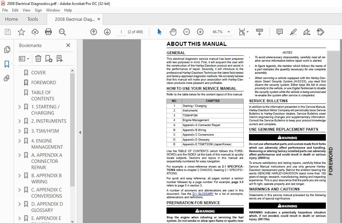
ABOUT THIS MANUAL
GENERAL:
- This electrical diagnostic service manual has been prepared with two purposes in mind. First, it will acquaint the user with the construction of the Harley-Davidson product and assist in the performance of repair.
- Secondly, it will introduce to the professional Harley-Davidson Technician the latest field-tested and factory-approved diagnostic methods.We sincerely believe that this manual will make your association with Harley-Davidson products more pleasant and profitable.
HOW TO USE YOUR SERVICE MANUAL:
Refer to the table below for the content layout of this manual.
NO. CHAPTER
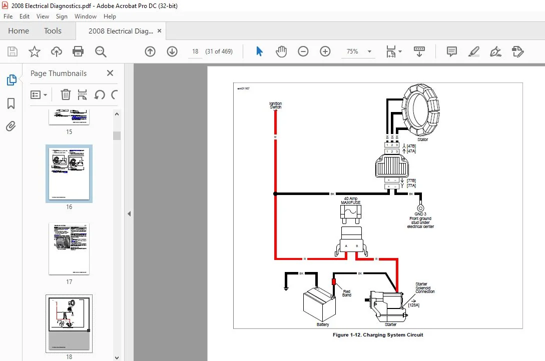
1 Starting / Charging
2 Instruments
3 TSM/HFSM
4 Engine Management
A Appendix A Connector Repair
B Appendix B Wiring
C Appendix C Conversions
D Appendix D Glossary
E Appendix E TSM/TSSM (Japan/Korea)
- Use the TABLE OF CONTENTS (which follows this FOREWORD) and the INDEX (at the back of this manual) to quickly locate subjects. Sections and topics in this manual are sequentially numbered for easy navigation.
- For example, a cross-reference shown as 2.1 SPECIFICATIONS refers to chapter 2 CHASSIS, heading 2.1 SPECIFICATIONS.
- For quick and easy reference, all pages contain a section number followed by a page number. For example, page 3-5 refers to page 5 in section 3.
- A number of acronyms and abbreviations are used in this document. See the D.1 GLOSSARY for a list of acronyms, abbreviations and definitions.
TABLE OF CONTENTS:
2008 Harley Davidson Dyna Models Electrical Diagnostics Manual – PDF DOWNLOAD
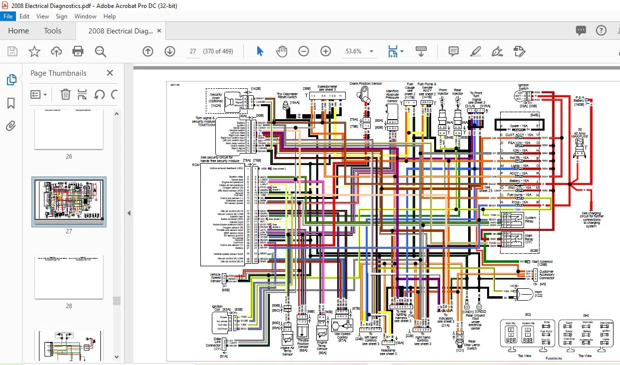
COVER............................................................  1
FOREWORD.........................................................  2
TABLE OF CONTENTS................................................  4
1. STARTING / CHARGING........................................... 12
	1.1 STARTER TROUBLESHOOTING.................................. 14
		General.................................................. 14
		Starter Troubleshooting.................................. 14
	1.2 STARTING SYSTEM DIAGNOSIS................................ 16
		Diagnostics.............................................. 16
	1.3 DIAGNOSTICS/TROUBLESHOOTING.............................. 25
		Voltage Drop............................................. 25
	1.4 STARTER ACTIVATION CIRCUITS.............................. 26
		Starter Activation Circuits.............................. 26
	1.5 TESTING STARTER ON MOTORCYCLE............................ 27
		Start Relay Test......................................... 27
		Starter Current Draw Test................................ 27
	1.6 TESTING STARTER ON BENCH................................. 28
		Free Running Current Draw Test........................... 28
		Starter Solenoid......................................... 28
		Solenoid Pull-In Test.................................... 28
		Solenoid Hold-In Test.................................... 28
		Solenoid Return Test..................................... 29
	1.7 CHARGING SYSTEM.......................................... 30
		General.................................................. 30
		Troubleshooting.......................................... 30
		Testing.................................................. 34
	1.8 BATTERY TESTING.......................................... 37
		General.................................................. 37
		Voltmeter Test........................................... 37
		Conductance Test......................................... 37
		Load Test................................................ 37
2. INSTRUMENTS................................................... 40
	2.1 CHECKING FOR DIAGNOSTIC TROUBLE CODES.................... 42
		Check Engine Lamp........................................ 42
		Security Lamp............................................ 43
		Code Types............................................... 44
		Retrieving Diagnostic Trouble Codes...................... 44
		Multiple Diagnostic Trouble Codes........................ 45
	2.2 INITIAL DIAGNOSTIC CHECK: SPEEDOMETER.................... 46
		General.................................................. 46
		Initial Diagnostics...................................... 47
	2.3 SPEEDOMETER SELF DIAGNOSTICS............................. 53
		General.................................................. 53
		Diagnostics.............................................. 53
	2.4 SPEEDOMETER/TACHOMETER................................... 56
		General.................................................. 56
		Speedometer Theory of Operation.......................... 56
		Odometer Theory of Operation............................. 57
		Tachometer Theory of Operation........................... 57
		Diagnostics.............................................. 57
	2.5 BREAKOUT BOX: SPEEDOMETER/TACHOMETER..................... 60
		General.................................................. 60
		Speedometer.............................................. 60
		Tachometer............................................... 60
	2.6 FUEL GAUGE............................................... 61
		Theory of Operation...................................... 61
		Fuel Gauge and Sender Test............................... 61
	2.7 INDICATOR LAMPS: ALL BUT FXDWG/FXDC/FXDF................. 62
		General.................................................. 62
		DIAGNOSTICS.............................................. 62
	2.8 INDICATOR LAMPS: FXDWG/FXDC/FXDF......................... 65
		General.................................................. 65
		Diagnostics.............................................. 65
	2.9 DTC B1004, B1005......................................... 68
		General.................................................. 68
		Diagnostics.............................................. 68
	2.10 DTC B1006, B1007........................................ 72
		General.................................................. 72
	2.11 DTC B1008............................................... 74
		General.................................................. 74
		Diagnostics.............................................. 74
	2.12 DTC U1016, U1255........................................ 77
		General.................................................. 77
		Diagnostics.............................................. 77
	2.13 DTC U1064, U1255........................................ 80
		General.................................................. 80
		Diagnostics.............................................. 80
	2.14 DTC U1300, U1301 OR BUS ER.............................. 83
		General.................................................. 83
		Diagnostics.............................................. 83
3. TSM/HFSM...................................................... 84
	3.1 TURN SIGNAL OVERVIEW..................................... 86
		General.................................................. 86
		Security System: Japan/Korea............................. 86
		Turn Signal Functions.................................... 86
		Manual Cancellation...................................... 86
		Automatic Cancellation................................... 86
		Bank Angle Functions..................................... 86
		Bank Angle Restart....................................... 86
		Clutch/Neutral Interlock................................. 86
		Security System H-DSSS................................... 86
	3.2 HARLEY-DAVIDSON SMART SECURITY SYSTEM.................... 87
		Components............................................... 87
		Security Immobilization.................................. 87
		HFSM Features............................................ 88
	3.3 H-DSSS ACTUATION......................................... 90
		General.................................................. 90
		Sidecar Configuration.................................... 90
		Actuation................................................ 90
		Fob Assignment........................................... 90
		Power Disruption and Configuring......................... 90
	3.4 PERSONAL IDENTIFICATION NUMBER (PIN)..................... 91
		General.................................................. 91
		Initial Pin Entry........................................ 91
		Changing the Pin......................................... 91
	3.5 ARMING/DISARMING SECURITY SYSTEM......................... 93
		Hands-Free Fob........................................... 93
		Security Lamp (Key Icon)................................. 93
		Arming................................................... 93
		Disarming................................................ 94
		Disarming with a Personal Identification Number (PIN).... 94
	3.6 WARNINGS AND ALARMS...................................... 95
		Warnings................................................. 95
		Alarm.................................................... 95
		Siren Chirp Mode (Confirmation).......................... 95
	3.7 SERVICE/EMERGENCY FUNCTIONS.............................. 96
		Transport Mode........................................... 96
		Service Mode............................................. 96
		Four-Way Flashing........................................ 96
	3.8 TROUBLESHOOTING.......................................... 97
		Turn Signals (TSM/HFSM).................................. 97
		Security System (HFSM)................................... 97
		Diagnostics Mode......................................... 97
		Troubleshooting.......................................... 97
	3.9 CHECKING FOR DIAGNOSTIC TROUBLE CODES.................... 98
		General.................................................. 98
		Security Lamp Diagnostics................................ 98
		Code Types............................................... 99
		Retrieving DTCs..........................................100
		Multiple DTCs/Priority Order.............................100
	3.10 INITIAL DIAGNOSTIC CHECK: TSM/HFSM......................102
		General..................................................102
		Initial Diagnostics......................................102
	3.11 SPEEDOMETER SELF DIAGNOSTICS............................107
		General..................................................107
		Diagnostics..............................................107
	3.12 BREAKOUT BOX: TSM/HFSM..................................109
		General..................................................109
		Installation.............................................109
		Removal..................................................109
	3.13 FAILS TO DISARM (HFSM ONLY).............................111
		General..................................................111
		Job/Time Codes...........................................111
		Diagnostics..............................................111
	3.14 DTC B0563...............................................114
		General..................................................114
		Diagnostics..............................................114
	3.15 TSM/HFSM: TURN SIGNAL ERRORS AND DTCS...................115
		General..................................................115
		Diagnostics..............................................115
	3.16 DTC B1131, B1132 (HFSM ONLY)............................128
		General..................................................128
		Diagnostics..............................................128
	3.17 DTC B1134 STARTER OUTPUT HIGH...........................131
		General..................................................131
		Diagnostics..............................................131
	3.18 DTC B1135...............................................134
		Diagnostics..............................................134
	3.19 DTC B1136, B1142 (HFSM ONLY)............................135
		Diagnostics..............................................135
	3.20 DTC B1141 (HFSM ONLY)...................................136
		Diagnostics..............................................136
	3.21 DTC B1143, B1144, B1145 (HFSM ONLY).....................141
		General..................................................141
		Diagnostics..............................................141
	3.22 DTC B1154, B1155........................................146
		Diagnostics..............................................146
	3.23 DTC U1016, U1255........................................150
		General..................................................150
		Diagnostics..............................................150
	3.24 DTC U1300, U1301 OR BUS ER..............................153
		Diagnostics..............................................153
	3.25 TSM/HFSM: PASSWORD LEARN................................154
		General..................................................154
		Password Learning........................................154
	3.26 HFSM MAINTENANCE........................................155
		General..................................................155
		Hands-Free Fob...........................................155
		Smart Siren (If Installed)...............................155
4. ENGINE MANAGEMENT.............................................158
	4.1 SPECIFICATIONS...........................................160
		Specifications...........................................160
	4.2 EFI SYSTEM...............................................161
		General..................................................161
		Troubleshooting..........................................161
	4.3 EFI DIAGNOSTIC INTRODUCTION..............................163
		System Problems..........................................163
		Resolving Problems.......................................163
	4.4 CHECKING FOR DIAGNOSTIC TROUBLE CODES: EFI...............164
		Check Engine Lamp........................................164
		Code Types...............................................165
		Retrieving Diagnostic Trouble Codes......................165
		Multiple Diagnostic Trouble Codes........................165
	4.5 INITIAL DIAGNOSTIC CHECK: EFI............................167
		General..................................................167
		Initial Diagnostics......................................167
	4.6 SPEEDOMETER SELF DIAGNOSTICS.............................176
		General..................................................176
		Diagnostics..............................................176
	4.7 BREAKOUT BOX: EFI........................................179
		General..................................................179
		Installation.............................................179
		Removal..................................................179
	4.8 WIGGLE TEST..............................................180
		General..................................................180
		Procedure................................................180
	4.9 INTAKE LEAK TEST.........................................181
		General..................................................181
		Leak Tester..............................................181
		Procedure................................................181
	4.10 ENGINE CRANKS, BUT WILL NOT START.......................183
		General..................................................183
		Diagnostics..............................................183
	4.11 NO ECM POWER............................................190
		General..................................................190
		Diagnostics..............................................190
	4.12 STARTS, THEN STALLS.....................................194
		General..................................................194
		Diagnostics..............................................194
	4.13 FUEL SYSTEM ELECTRICAL TEST.............................199
		General..................................................199
		Diagnostics..............................................199
	4.14 SYSTEM RELAY FAULT......................................206
		General..................................................206
		Diagnostics..............................................206
	4.15 FUEL PRESSURE TEST......................................212
		General..................................................212
		Testing..................................................212
		Diagnostics..............................................213
	4.16 IDLE AIR CONTROL........................................216
		General..................................................216
		Diagnostics..............................................216
	4.17 MISFIRE AT IDLE OR UNDER LOAD...........................221
		General..................................................221
		Diagnostics..............................................221
	4.18 COMBUSTION ABSENT INTERMITTENT..........................227
		General..................................................227
		Diagnostics..............................................227
	4.19 DTC P0107, P0108........................................232
		General..................................................232
		Diagnostics..............................................232
	4.20 DTC P0112, P0113........................................236
		General..................................................236
		Diagnostics..............................................236
	4.21 DTC P0117, P0118........................................240
		General..................................................240
		Diagnostics..............................................240
	4.22 DTC P0122, P0123........................................244
		General..................................................244
		Diagnostics..............................................244
	4.23 DTC P0131, P0132, P0134, P0151, P0152, P0154............248
		General..................................................248
		Diagnostics..............................................248
	4.24 DTC P0261, P0262, P0263, P0264..........................254
		General..................................................254
		Diagnostics..............................................254
	4.25 DTC P0373, P0374........................................260
		General..................................................260
		Diagnostics..............................................260
	4.26 DTC P0501, P0502........................................263
		General..................................................263
		Diagnostics..............................................263
	4.27 DTC P0562, P0563........................................267
		General..................................................267
		Diagnostics..............................................267
	4.28 DTC P0603, P0605........................................271
		General..................................................271
		Diagnostics..............................................271
	4.29 DTC P0661, P0662........................................272
		General..................................................272
		Diagnostics..............................................272
	4.30 DTC P1009, P1010........................................276
		General..................................................276
		Diagnostics..............................................276
	4.31 DTC P1351, P1352, P1354, P1355..........................279
		General..................................................279
		Diagnostics..............................................279
	4.32 DTC P1475, P1477, P1478.................................284
		General..................................................284
		Diagnostics..............................................284
	4.33 DTC P1501, P1502........................................290
		General..................................................290
		Diagnostics..............................................290
	4.34 DTC U1064, U1255........................................295
		General..................................................295
		Diagnostics..............................................295
	4.35 DTC U1097, U1255........................................298
		General..................................................298
		Diagnostics..............................................298
A. APPENDIX A CONNECTOR REPAIR...................................302
	A.1 AMP 1-PLACE CONNECTORS...................................304
		AMP 1-Place Connector Repair.............................304
	A.2 AMP MULTILOCK CONNECTORS.................................306
		AMP Multilock Connector Repair...........................306
	A.3 DELPHI CONNECTORS........................................311
		Delphi Connector Repair..................................311
	A.4 DEUTSCH 1-PLACE ELECTRICAL CONNECTORS....................313
		Deutsch 1-Place Connector Repair.........................313
	A.5 DEUSCH ELECTRICAL CONNECTORS.............................314
		Deutsch Connector Repair.................................314
	A.6 DEUTSCH STANDARD TERMINALS...............................318
		Deutsch Standard Terminal Crimps.........................318
	A.7 DEUTSCH MINI-TERMINAL CRIMPS.............................319
		Deutsch Mini Terminal Crimps.............................319
	A.8 DEUTSCH SOLID BARREL TERMINALS...........................320
		Deutsch Solid Barrel Terminal Crimps.....................320
	A.9 RELAY AND FUSE BLOCKS....................................322
		Fuse Block Repair........................................322
	A.10 150 METRI-PACK CONNECTORS...............................323
		150 Metri-Pack Connector Repair..........................323
	A.11 280 METRI-PACK CONNECTORS...............................325
		280 Metri-Pack Connector Repair..........................325
	A.12 480 METRI-PACK CONNECTORS...............................327
		480 Metri-Pack Connector Repair..........................327
	A.13 630 METRI-PACK CONNECTORS...............................328
		630 Metri-Pack Connector Repair..........................328
	A.14 800 METRI-PACK CONNECTORS...............................329
		Delphi Maxi-Fuse Housing Repair..........................329
	A.15 METRI-PACK TERMINALS....................................331
		Metri-Pack Terminal Crimps...............................331
	A.16 MOLEX CONNECTORS........................................333
		Molex Connector Repair...................................333
	A.17 PACKARD ECM CONNECTOR...................................335
		Packard 100W Connector Repair............................335
	A.18 PACKARD MICRO-64 CONNECTORS.............................337
		Packard Micro-64 Connector Repair........................337
	A.19 SEALED SPLICE CONNECTORS................................340
		Sealed Splice Connector Repair...........................340
B. APPENDIX B WIRING.............................................342
	B.1 CONNECTORS...............................................344
		Connector Locations......................................344
	B.2 WIRING DIAGRAMS..........................................346
		Wiring Diagram Information...............................346
		2008 Dyna Wiring Diagrams................................347
C. APPENDIX C CONVERSIONS........................................392
	C.1 METRIC CONVERSION........................................394
		Conversion Table.........................................394
	C.2 FLUID CONVERSIONS........................................395
		United States System.....................................395
		Metric System............................................395
		British Imperial System..................................395
	C.3 TORQUE CONVERSIONS.......................................396
		United States System.....................................396
		Metric System............................................396
D. APPENDIX D GLOSSARY...........................................398
	D.1 GLOSSARY.................................................400
		Acronyms and Abbreviations...............................400
E. APPENDIX E TSM/TSSM (JAPAN/KOREA).............................402
	E.1 TSM/TSSM (JAPAN/KOREA) OVERVIEW..........................404
		General..................................................404
		Troubleshooting..........................................404
	E.2 TSM/TSSM FEATURES........................................406
		General..................................................406
		Turn Signal Functions....................................406
		Bank Angle Function......................................406
		Clutch/Neutral Interlock Functions.......................406
		Security Alarm and Immobilization Functions..............406
	E.3 VEHICLE DELIVERY.........................................408
		General..................................................408
		Configuring A TSSM.......................................408
		Sidecar Configuration....................................408
		Power Disruption and Configuring.........................408
		Key Fob Assignment: TSSM.................................408
		Pin Entry: TSSM..........................................409
		Changing the Pin: TSSM...................................411
	E.4 TURN SIGNAL FUNCTIONS....................................412
		General..................................................412
		Automatic Cancellation...................................412
		Manual Cancellation......................................412
		Four-Way Flashing........................................412
		Diagnostics Mode.........................................412
	E.5 BANK ANGLE FUNCTION......................................413
		General..................................................413
		Operation................................................413
	E.6 SECURITY SYSTEM FUNCTIONS (TSSM ONLY)....................414
		General..................................................414
		Alarm Sensitivity: TSSM..................................414
		Auto-Arming Function: TSSM...............................415
		Storage Mode: TSSM.......................................416
	E.7 ARMING/DISARMING (TSSM ONLY).............................417
		General..................................................417
		Security Lamp............................................417
		Using Key FOB: TSSM......................................417
		Using the Pin............................................417
	E.8 DIAGNOSTIC TROUBLE CODES (DTC)...........................419
		TSM/TSSM.................................................419
		Code Types...............................................420
		Retrieving Diagnostic Trouble Codes......................421
		Multiple Diagnostic Trouble Codes........................421
	E.9 INITIAL DIAGNOSTIC CHECK: TSM/TSSM.......................422
		General..................................................422
		Initial Diagnostics......................................422
	E.10 SPEEDOMETER SELF DIAGNOSTICS............................428
		General..................................................428
		Diagnostics..............................................428
	E.11 BREAKOUT BOX: TSM/TSSM..................................431
		General..................................................431
		Installation.............................................431
		Removal..................................................431
	E.12 FAILS TO DISARM (TSSM ONLY).............................432
		General..................................................432
		Diagnostics..............................................432
	E.13 TURN SIGNAL ERRORS: B1121, B1122, B1141.................435
		General..................................................435
		Diagnostics..............................................435
	E.14 DTC B0563...............................................445
		General..................................................445
		Diagnostics..............................................445
	E.15 DTC B1131, B1132........................................446
		General..................................................446
		Diagnostics..............................................446
	E.16 DTC B1134...............................................449
		General..................................................449
		Diagnostics..............................................449
	E.17 DTC B1135...............................................452
		General..................................................452
	E.18 DTC B1154, B1155........................................453
		General..................................................453
		Diagnostic Notes.........................................453
	E.19 DTC U1016, U1255........................................457
		General..................................................457
		Diagnostics..............................................457
	E.20 DTC U1300, U1301 OR BUS ER..............................460
		General..................................................460
		Diagnostics..............................................460
	E.21 TSM/TSSM: PASSWORD LEARN................................461
		General..................................................461
		Password Learning........................................461
	E.22 TSSM MAINTENANCE........................................462
		General..................................................462
		Key FOB..................................................462
		Siren (If Installed).....................................462
TOOLS............................................................  0
TORQUE VALUES....................................................  0
INDEX............................................................464
2008 HARLEY DAVIDSON DYNA MODELS ELECTRICAL DIAGNOSTICS MANUAL – PDF DOWNLOAD:
PLEASE NOTE:
- This is the SAME exact manual used by your dealers to fix your vehicle.
- The same can be yours in the next 2-3 mins as you will be directed to the download page immediately after paying for the manual.
- Any queries / doubts regarding your purchase, please feel free to contact [email protected]
S.V