Trusted Business
Verified & Licensed
Virus Free Files
100% Safe Downloads
Secure Payment
SSL Protected
Instant Delivery
Available Immediately
Sale!


2008 Honda CBR1000RR Service Manual – PDF DOWNLOAD 
2008 Honda CBR1000RR Service Manual – PDF DOWNLOAD

2008 Honda CBR1000RR Service Manual – PDF DOWNLOAD
Original price was: $89.95.$23.95Current price is: $23.95.
2008 Honda CBR1000RR Service Manual – PDF DOWNLOAD
Instant PDF Download
Available immediately
Save to Your Device
Download & keep forever
Antivirus Scanned
100% virus-free
Trusted Worldwide
175,000+ customers
Description
2008 Honda CBR1000RR Service Manual – PDF DOWNLOAD
DESCRIPTION:
2008 Honda CBR1000RR Service Manual – PDF DOWNLOAD
A Few Words About Safety
Service Information
- The service and repair information contained in this manual is intended for use by qualllied. professional techniciens. Attempting service or repairs without the proper training. tools. and equipment could cause injury to you or others. it could also damage the vehicle or create an unsaie condition.
- This manual describes the proper methods and procedures for performing service. maintenance, and repaire. Some procedures require the use of specially designed tools and dedicated equipment. Any person who intends to use a replacement part.
- service procedure or a tool that is not recommended by Honda. must determine the risks to their personal safety and the safe operation of the vehicle. If you need to replace a part. use genuine Honda parts with the correct part number or en equivalent part. We strongly recommend that you do not use replacement parts of inferior quality.
important Safety Precautions
Make sure you have a clear understanding of all basic shop safety practices and that you are wearing appropriate clothing ane“ using safety equipment. When performing any service task. be especially careful of the following:
° Read all of the instructions before you begin, and make sure you have the tools. the replacement or repair parts. and the skills required to perform the tasks saier and completely.
° Protect your eyes by using proper safety glasses. goggies or face shieids any time you hammer. drill, grind, pry or work around pressurized air or liquide. and springs or other stored—energy components. if there is any doubt. put on eye protection.
° Use other protective wear when necessary. for example gioves or safety shoes. Handling hot or sharp parts can cause severe burns or cute. Before you grab something that looks like it can hurt you. stop and put on gloves.
° Protect yourself and others whenever you have the vehicle up in the air. Any time you lift the vehicle, either with a hoist or a jack. make sure that it is always securely supported. Use jack stands.
Make sure the engine is off before you begin any servicing procedures. unless the instruction tells you to do otherwise. This will help eliminate several potential hazards: *
° Carbon monoxide poisoning from engine exhaust. Be sure there is adequate ventilation whenever you run the engine.
° Burns from hot parts or coolant. Let the engine and exhaust system cool before working in those areas.
° injury from moving parts. if the instruction tells you to run the engine, be sure your hands, fingers and clothing are out of the way. Gasoline vapors and hydrogen gases from batteries are explosive. To reduce the possibility of a fire or explosion. be careful when working around gasoline or batteries.
° Use only & nonflammabie solvent. not gasoline. fo clean parts.
° Never drain or store gasoline in en open container.
° Keep all cigarettes, sparks and fiames away from the battery and all fuel-related parts. —
TABLE OF CONTENTS:
2008 Honda CBR1000RR Service Manual – PDF DOWNLOAD
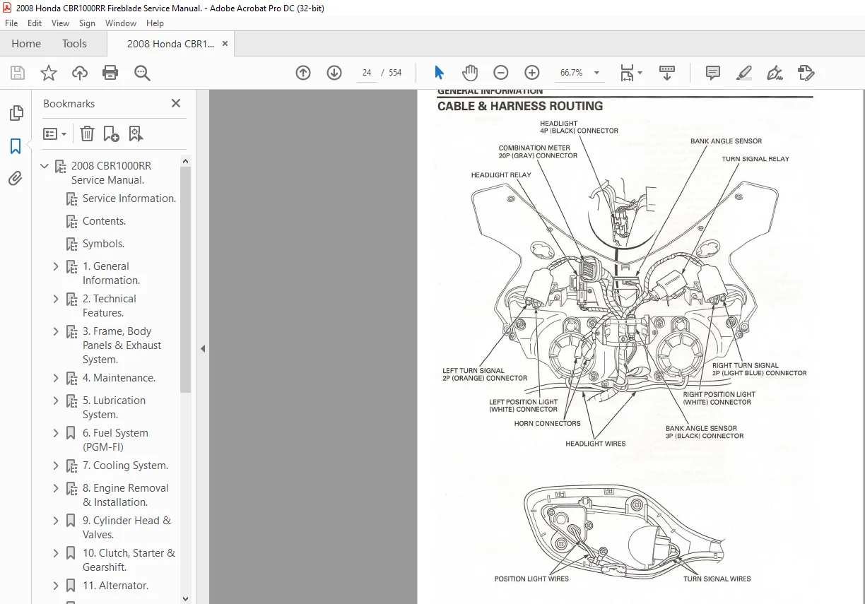
2008 CBR1000RR Service Manual.
......................................  1
	Service Information.
............................................  2
	Contents.
.......................................................  3
	Symbols.
........................................................  4
	1.
General Information. .........................................  5
		1.1 Contents.
...............................................  5
		1.2 Service Rules.
 .........................................  6
		1.3 Model Identification.
...................................  7
			1.4 Labels.
.............................................  8
		1.5 General Specifications.
.................................  9
			1.6 Electrical Specifications.
.......................... 10
		 1.7 Lubrication, Fuel & Cooling
System Specifications. .... 11
		1.8 Cylinder Head & Valve Specifications.
................... 12
		1.9 Crankcase, Transmission & Balancer
 Specifications. ..... 13
		1.10 Wheel, Suspension & Steering Specifications.
........... 14
		1.11 Brake, Battery & Ignition Specifications.
.............. 15
		1.12 Lights, Meters & Switches Specifications.
.............. 16
		1.13 Torque Values.
 ........................................ 17
			1.14 Lubrication, Fuel & Cooling.
....................... 18
			1.15 Cylinder Head, Clutch & Starter.
................... 19
			1.16 Crank, Wheels & Suspension.
........................ 20
			1.17 Brakes, Starter & Lights.
.......................... 21
		1.18 Lubrication & Seal Points.
............................. 22
			1.19 Frame.
............................................. 23
		1.20 Cable & Harness Routing.
............................... 24
			1.21 IDC.
............................................... 25
			1.22 Throttle & Clutch.
................................. 26
			1.23 Brakes.
............................................ 27
			1.24 ECM.
............................................... 28
			1.25 Injectors.
......................................... 29
			1.26 HESD.
.............................................. 30
			1.27 Fuel Pump.
......................................... 31
			1.28 PAIR & Fan.
........................................ 32
			1.29 Starter & Battery.
................................. 33
			1.30 Oil Cooler & Sidestand.
............................ 34
			1.31 Radiator.
.......................................... 35
			1.32 Sub Harness.
....................................... 36
			1.33 Tail & Signals.
.................................... 37
			1.34 EGCA.
.............................................. 38
			1.35 EVAP (California).
................................. 39
			1.36 EVAP Purge.
........................................ 40
		1.37 Emission Control Systems.
.............................. 41
			1.38 Exhaust ECS
. ...................................... 42
			1.39 Evaporative ECS
.................................... 43
	2.
Technical Features. .......................................... 44
		2.1 Contents.
............................................... 44
		2.2 Exhaust System.
......................................... 45
			2.3 EGBV. ............................................... 46
			2.4 ECV.
................................................ 47
		2.5 CMP Sensor.
............................................. 48
		2.6 Fan Motor Control System.
............................... 49
		2.7 Clutch System.
.......................................... 50
			2.8 Clutch Mechanism.
................................... 51
			2.9 Clutch Assist.
...................................... 52
	3.
Frame, Body Panels & Exhaust System.  ........................ 53
		3.1 Contents.
............................................... 53
		3.2 Body Panel Locations.
................................... 54
		3.3 Service Information.
.................................... 55
		3.4 Trim Clips.
............................................. 56
			3.5 Trim Clip 3.
........................................ 57
		3.6 Seat, Side Covers & Pillion Seat. ....................... 58
		3.7 Tank Cover.
............................................. 59
		3.8 Rear Seat Cowl.
......................................... 60
		3.9 Upper Inner Cover & Lower Cowl
. ........................ 61
		3.10 Middle Cowl.
........................................... 62
		3.11 Mirrors.
............................................... 63
			3.12 Windscreen.
........................................ 64
		3.13 Upper Cowl.
............................................ 65
			3.14 Vacuum Chamber.
.................................... 66
			3.15 Lights.
............................................ 67
			3.16 Bank Angle Sensor.
................................. 68
			3.17 Wire Harness.
...................................... 69
		3.18 Front Fender.
.......................................... 70
		3.19 Rear Fender. ........................................... 71
			3.20 Rear Fender C
. .................................... 72
		3.21 License Light Stay.
.................................... 73
			3.22 Undertray.
......................................... 74
		3.23 Seat Rail.
............................................. 75
		3.24 Muffler.
............................................... 76
			3.25 EGCA Cable.
........................................ 77
			3.26 Disassembly.
....................................... 78
			3.27 Assembly.
.......................................... 79
			3.28 Heat Guard.
........................................ 80
			3.29 Installation.
...................................... 81
			3.30 Main Step Bracket.
................................. 82
		3.31 Exhaust Pipe.
.......................................... 83
			3.32 Installation.
...................................... 84
			3.33 Headers.
........................................... 85
			3.34 Mountings.
......................................... 86
	4.
Maintenance. ................................................. 87
		4.1
Contents................................................ 87
		4.2 Service Information.
.................................... 88
		4.3 Tools.
.................................................. 89
		4.4 Maintenance Schedule.
................................... 90
		4.5 Fuel Line.
.............................................. 91
			4.6 Inspection.
......................................... 92
			4.7 Fuel Tank.
.......................................... 93
		4.8 Throttle Operation.
..................................... 94
		4.9 Air Cleaner.
............................................ 95
		4.10 Spark Plug.
............................................ 96
			4.11 Inspection.
........................................ 97
		4.12 Valve Clearance.
....................................... 98
			4.13 Timing.
............................................ 99
			4.14 Intake & Exhaust Valves.
...........................100
			4.15 Adjustment.
........................................101
			4.16 Shims.
.............................................102
		4.17 Engine Oil.
............................................103
			4.18 Filter Change.
.....................................104
			4.19 Sump.
..............................................105
		4.20 Radiator Coolant.
......................................106
		4.21 Secondary Air Supply.
..................................107
		4.22 EVAP (California).
.....................................108
		4.23 EGCA Cable.
............................................109
			4.24 Cable Inspection.
..................................110
			4.25 Adjustment.
........................................111
		4.26 Drive Chain.
...........................................112
			4.27 Cleaning & Lubrication.
. ..........................113
			4.28 Sprockets.
.........................................114
			4.29 Chain Replacement.
.................................115
			4.30 Chain Links.
.......................................116
		4.31 Brake Fluid.
...........................................117
		4.32 Brake Pads Wear.
.......................................118
		4.33 Brake Light Switch.
....................................119
		4.34 Headlight & Clutch.
....................................120
		4.35 Sidestand & Suspension.
................................121
			4.36 Front Suspension.
..................................122
			4.37 Rear Suspension.
...................................123
		4.38 Nuts, Bolts & Fasteners.
...............................124
		4.39 Wheels & Tires.
........................................125
		4.40 Steering Head Bearings.
................................126
	5.
Lubrication System. ..........................................127
		5.1 Contents.
...............................................127
		5.2
Lubrication System Diagram. .............................128
		5.3 Service Information.
....................................129
		5.4 Troubleshooting.
........................................130
		5.5 Oil Pressure Inspection.
................................131
			5.6 Oil Pump.
...........................................132
			5.7 Disassembly.
........................................133
			5.8 Inspection.
.........................................134
			5.9 Assembly.
...........................................135
			5.10 Installation.
......................................136
			5.11 Sprockets.
.........................................137
			5.12 Sump.
..............................................138
		5.13 Oil Cooler.
............................................139
			5.14 Installation.
......................................140
	6.
Fuel System (PGM-FI) .........................................141
		6.1 Contents.
...............................................141
		6.2 Component Location.
.....................................142
		6.3 Service Information.
....................................143
			6.4 Specifications.
.....................................144
			6.5 Tools.
..............................................145
			6.6 Tools (Cont)
. ......................................146
		6.7 PGM-FI Symptom Troubleshooting.
.........................147
		6.8 PGM-FI System Location.
.................................148
		6.9 PGM-FI System Diagram.
..................................149
		6.10 Connector Location.
....................................150
		6.11 ECM Connectors.
........................................151
		6.12 PGM-FI Troubleshooting Information.
....................152
			6.13 HDS Information.
...................................153
			6.14 Clearing DTC.
......................................154
		6.15 DTC Index.
.............................................155
			6.16 DTC Index.
.........................................156
		6.17
DTC Troubleshooting. ...................................157
			6.18 MAP
Sensor Output. . ...............................158
			6.19 MAP
Sensor Input. ..................................159
			6.20 MAP
Sensor Inspection. .............................160
			6.21 ECT Resistance
. ...................................161
			6.22 ECT Sensor Output.
.................................162
			6.23 TP Sensor.
.........................................163
			6.24 TP Sensor HV.
......................................164
			6.25 IAT Sensor LV.
.....................................165
			6.26 IAT Sensor Inspection.
.............................166
			6.27 VS Sensor Input.
...................................167
			6.28
Primary Injector. ..................................168
			6.29 Injector Inspection.
...............................169
			6.30 CMP Sensor.
........................................170
			6.31 CMP Sensor Input.
..................................171
			6.32 CKP
Sensor Inspection. .............................172
			6.33 Knock Sensor Inspection.
...........................173
			6.34 Knock Sensor LV.
...................................174
			6.35 IACV Inspection.
...................................175
			6.36 ECV Pot LV.
........................................176
			6.37 ECV Pot
Inspection. ................................177
			6.38 ECV Pot HV.
........................................178
			6.39 EGCA Lock.
.........................................179
		6.40 MIL Circuit Troubleshooting.
...........................180
		6.41 Fuel Line Inspection.
..................................181
			6.42 Fuel Rail.
.........................................182
			6.43 Quick Connect Fitting.
.............................183
			6.44 Fuel Pressure Test.
................................184
			6.45 Tools.
.............................................185
			6.46 Fuel Flow Inspection.
..............................186
		6.47 Fuel Pump Unit
.........................................187
			6.48 Removal.
...........................................188
			6.49 Installation.
......................................189
		6.50 Fuel Pump Relay.
.......................................190
		6.51 Fuel Tank.
.............................................191
		6.52 Air Cleaner Housing.
...................................192
			6.53 Removal.
...........................................193
			6.54 Installation.
......................................194
		6.55 Secondary Injector.
....................................195
			6.56 Removal.
...........................................196
			6.57 Installation.
......................................197
		6.58 Throttle Body.
.........................................198
			6.59 Removal.
...........................................199
			6.60 Diagram.
...........................................200
			6.61 Hose Routing.
......................................201
			6.62 Installation.
......................................202
		6.63 Primary Injector.
......................................203
			6.64 Removal.
...........................................204
			6.65 Installation.
......................................205
		6.66 Engine Idle Speed.
.....................................206
			6.67 Removal/Installation.
..............................207
		6.68 Knock Sensor.
..........................................208
		6.69 MAP Sensor.
............................................209
		6.70 IAT &
ECT Sensor. ......................................210
		6.71 CMP
Sensor. ............................................211
			6.72 Bank Angle Sensor.
.................................212
		6.73 Engine Stop Relay.
.....................................213
		6.74 ECM.
...................................................214
			6.75 Power Line Inspection.
.............................215
			6.76 Engine Stop Relay Inspection.
......................216
		6.77 Secondary Air Supply System.
...........................217
			6.78 PAIR Control Solenoid.
.............................218
		6.79 EGCA.
..................................................219
			6.80 Inspection.
........................................220
		6.81 Intake Air Duct Control.
...............................221
			6.82 One-Way Valve.
.....................................222
		6.83 EVAP (California).
.....................................223
			6.84 Removal.
...........................................224
			6.85 Installation.
......................................225
	7.
Cooling System. ..............................................226
		7.1 Contents.
...............................................226
		7.2 System Flow Pattern.
....................................227
		7.3 Service Information.
....................................228
		7.4 Troubleshooting.
........................................229
		7.5 System Testing.
.........................................230
		7.6 Coolant Replacement.
....................................231
			7.7 Replacement/Air Bleeding.
...........................232
		7.8 Thermostat.
.............................................233
			7.9 Inspection.
.........................................234
			7.10 Installation.
......................................235
		7.11 Radiator/Cooling Fan.
..................................236
			7.12 Removal.
...........................................237
			7.13 Disassembly.
.......................................238
			7.14 Cooling Fan.
.......................................239
			7.15 Fan Motor.
.........................................240
			7.16 Assembly.
..........................................241
			7.17 Fittings.
..........................................242
			7.18 Alignment.
.........................................243
			7.19 Installation.
......................................244
			7.20 Connections.
.......................................245
		7.21 Water Pump.
............................................246
			7.22 Installation.
......................................247
			7.23 Connections.
.......................................248
		7.24 Radiator Reserve Tank.
.................................249
	8.
Engine Removal & Installation.................................250
		8.1 Contents.
...............................................250
		8.2 Component Location.
.....................................251
		8.3 Service Information.
....................................252
		8.4 Engine Removal.
.........................................253
			8.5 Sensors.
............................................254
			8.6 Mountings.
..........................................255
			8.7 Tools.
..............................................256
		8.8 Engine Installation.
....................................257
			8.9 Frame.
..............................................258
			8.10 Mountings.
.........................................259
			8.11 Brackets.
..........................................260
			8.12 Fittings.
..........................................261
			8.13 Sensors
............................................262
			8.14 Switches.
..........................................263
	9.
Cylinder Head & Valves. ......................................264
		9.1 Contents.
...............................................264
		9.2 Component Location.
.....................................265
		9.3 Service Information.
....................................266
			9.4 Tools.
..............................................267
			9.5 Tools.
..............................................268
		9.6 Troubleshooting.
........................................269
		9.7 Cylinder Compression Test.
..............................270
		9.8 Cylinder Head Cover Disassembly.
........................271
		9.9 Camshaft Removal.
.......................................272
			9.10 Cam Sprocket.
......................................273
			9.11 Cam Chain.
.........................................274
			9.12 Inspection.
........................................275
			9.13 Camshaft Oil Clearance.
............................276
		9.14 Cylinder Head Removal.
.................................277
		9.15 Cylinder Head Disassembly.
.............................278
			9.16 Tools.
.............................................279
		9.17 Cylinder Head Inspection.
..............................280
			9.18 Valve Springs.
.....................................281
			9.19 Valve Guide.
.......................................282
		9.20 Valve Guide Replacement.
...............................283
		9.21 Valve Seat Inspection.
.................................284
			9.22 Valve Seat Refacing.
...............................285
			9.23 Tools.
.............................................286
		9.24 Cylinder Head Assembly.
................................287
			9.25 Tools.
.............................................288
		9.26 Cylinder Head Installation.
............................289
			9.27 Cam Chain Tensioner.
...............................290
			9.28 Cylinder Layout.
...................................291
			9.29 Tightening Sequence.
...............................292
		9.30 Camshaft Installation.
.................................293
			9.31 Alignment.
.........................................294
			9.32 Identification.
....................................295
			9.33 Cam Sprockets.
.....................................296
		9.34 Cylinder Head Cover Assembly.
..........................297
		9.35 Cylinder Head Cover Installation.
......................298
			9.36 Fixings.
...........................................299
		9.37 Cam Chain Tensioner Lifter.
............................300
			9.38 Tensioner Stopper.
.................................301
	10. Clutch, Starter & Gearshift.
................................302
		10.1 Contents.
..............................................302
		10.2 Component Location.
....................................303
		10.3 Service Information.
...................................304
		10.4 Troubleshooting.
.......................................305
		10.5 Right Crankcase Cover Removal.
.........................306
			10.6 Clutch Lifter Lever.
...............................307
		10.7 Clutch.
................................................308
			10.8 Clutch Center Lock Nut.
............................309
			10.9 Pressure Plate.
....................................310
			10.10 Clutch Outer.
.....................................311
			10.11 Inspection.
.......................................312
			10.12 Clutch Spring.
....................................313
			10.13 Clutch Disc.
......................................314
			10.14 Primary Driven Gear.
..............................315
			10.15 Mainshaft.
........................................316
			10.16 Needle Bearing Selection.
.........................317
			10.17 Installation.
.....................................318
			10.18 Reduction Gear.
...................................319
			10.19 Clutch Plates.
....................................320
			10.20 Clutch Assembly.
..................................321
			10.21 Clutch Holder.
....................................322
			10.22 Lifter Plate.
.....................................323
		10.23 Starter Clutch.
.......................................324
			10.24 Inspection.
.......................................325
			10.25 Assembly.
.........................................326
			10.26 Installation.
.....................................327
		10.27 Gearshift Linkage.
....................................328
			10.28 Inspection.
.......................................329
			10.29 Installation.
.....................................330
		10.30 Right Crankcase Cover.
................................331
			10.31 Gaskets.
..........................................332
			10.32 Clutch Cable.
.....................................333
	11.
Alternator. .................................................334
		11.1 Contents.
..............................................334
		11.2
Component Location. ....................................335
		11.3 Service Information.
...................................336
		11.4 Alternator Cover Removal.
..............................337
		11.5 Stator.
................................................338
		11.6 Flywheel.
..............................................339
		11.7 Alternator Cover Installation.
.........................340
			11.8 Sensors.
...........................................341
	12. Crankcase, Transmission & Balancer.
.........................342
		12.1 Contents.
..............................................342
		12.2 Component Location.
....................................343
		12.3 Service Information.
...................................344
		12.4 Troubleshooting.
.......................................345
		12.5 Crankcase Separation.
..................................346
		12.6 Shift Fork, Drum & Transmission.
.......................347
			12.7 Removal.
...........................................348
			12.8 Shift Fork & Drum Inspection.
......................349
			12.9 Transmission Inspection.
...........................350
			12.10 Mainshaft Bearing. ................................351
			12.11 Mainshaft Bearing Replacement.
....................352
			12.12 Transmission Assembly.
............................353
			12.13 Gear & Shafts.
....................................354
			12.14 Installation.
.....................................355
			12.15 Fork Shaft.
.......................................356
		12.16 Balancer.
.............................................357
			12.17 Inspection.
.......................................358
			12.18 Balancer Bearing Selection.
.......................359
			12.19 Disassembly.
......................................360
			12.20 Installation.
.....................................361
			12.21 Balancer Gear Backlash Adjuster.
..................362
		12.22 Crankcase Assembly.
...................................363
			12.23 Tightening Mehod.
.................................364
			12.24 Hoses & Seals.
....................................365
	13. Crankshaft, Piston & Cylinder.
..............................366
		13.1 Contents.
..............................................366
		13.2 Component Location.
....................................367
		13.3 Service Information.
...................................368
		13.4 Troubleshooting.
.......................................369
		13.5 Crankshaft.
............................................370
			13.6 Inspection.
........................................371
			13.7 Installation.
......................................372
			13.8 Connecting Rods.
...................................373
		13.9 Main Journal Bearing.
..................................374
			13.10 Bearing Selection.
................................375
			13.11 Bearing Installation.
.............................376
		13.12 Crankpin Bearing.
.....................................377
			13.13 Bearing Selection.
................................378
		13.14 Piston & Cylinder.
....................................379
			13.15 Removal.
..........................................380
			13.16 Piston Inspection.
................................381
			13.17 Connecting Rod Inspection.
........................382
			13.18 Cylinder Inspection.
..............................383
			13.19 Piston Assembly.
..................................384
			13.20 Piston Installation.
..............................385
			13.21 Tightening Method.
................................386
	14. Front Wheel, Suspension & Steering.
.........................387
		14.1 Contents.
..............................................387
		14.2 Component Location.
....................................388
		14.3 Service Information.
...................................389
			14.4 Tools.
.............................................390
			14.5 Tools (Cont).
......................................391
		14.6 Troubleshooting.
.......................................392
		14.7 HESD Troubleshooting.
..................................393
			14.8 DTC Troubleshooting.
...............................394
		14.9 Handlebars.
............................................395
			14.10 Throttle.
.........................................396
			14.11 Top Yoke.
.........................................397
			14.12 Installation.
.....................................398
			14.13 Steering Damper.
..................................399
			14.14 Grips.
............................................400
			14.15 Handlebar
Weights..................................401
		14.16 Front Wheel.
..........................................402
			14.17 Inspection.
.......................................403
			14.18 Wheel Balance.
....................................404
			14.19 Disassembly.
......................................405
			14.20 Installation.
.....................................406
			14.21 Tightening.
.......................................407
		4.22 Fork.
..................................................408
			4.23 Removal.
...........................................409
			4.24 Stopper Plate.
.....................................410
			4.25 Fork Damper.
.......................................411
			4.26 Inspection.
........................................412
			4.27 Assembly.
..........................................413
			4.28 Oil Seals.
.........................................414
			4.29 Slider.
............................................415
			4.30 Bleeding.
..........................................416
			4.31 Compression.
.......................................417
			4.32 Installation.
......................................418
		14.33 HESD.
.................................................419
		14.34 Steering Stem.
........................................420
			14.35 Bearing Replacement.
..............................421
			14.36 Driver Shaft.
.....................................422
			14.37 Assembly Base.
....................................423
			14.38 Tools.
............................................424
			14.39 Upper Bearings.
...................................425
			14.40 Lower Inner Race Replacement.
.....................426
			14.41 Bearings.
.........................................427
			14.42 Steering Head Bearing Pre-Load.
...................428
	15. Rear Wheel & Suspension.
....................................429
		15.1 Contents.
..............................................429
		15.2 Component Location.
....................................430
		15.3 Service Information.
...................................431
			15.4 Tools.
.............................................432
		15.5 Troubleshooting.
.......................................433
		15.6 Rear Wheel.
............................................434
			15.7 Disassembly.
.......................................435
			15.8 Inspection.
........................................436
			15.9 Driven Flange Bearing Replacement.
.................437
			15.10 Wheel Bearing Replacement.
........................438
			15.11 Assembly.
.........................................439
			15.12 Installation.
.....................................440
		15.13 Suspension Linkage.
...................................441
		15.14 Shock Absorber.
.......................................442
			15.15 Inspection.
.......................................443
			15.16 Lower Bearing.
....................................444
			15.17 Shock Absorber Disposal.
..........................445
		15.18 Swingarm.
.............................................446
			15.19 Disassembly.
......................................447
			15.20 Inspection.
.......................................448
			15.21 Bearings.
.........................................449
			15.22 Shock Arm.
........................................450
			15.23 Assembly.
.........................................451
			15.24 Installation.
.....................................452
			15.25 Hose Routing.
.....................................453
	16. Hydraulic Brake.
............................................454
		16.1 Contents.
..............................................454
		16.2 Component Location.
....................................455
			16.3 Rear.
..............................................456
		16.4 Service Information.
...................................457
		16.5 Troubleshooting.
.......................................458
		16.6 Brake Fluid Replacement.
...............................459
			16.7 Air Bleeding.
......................................460
		16.8 Brake Pad & Disc.
......................................461
			16.9 Front Brake Pad Replacement.
.......................462
			16.10 Rear Brake Pad Replacement.
.......................463
			16.11 Brake Disc Inspection.
............................464
		16.12 Front Master Cylinder.
................................465
			16.13 Disassembly.
......................................466
			16.14 Inspection.
.......................................467
			16.15 Assembly.
.........................................468
			16.16 Brake Light Switch.
...............................469
			16.17 Installation.
.....................................470
		16.18 Rear Master Cylinder.
.................................471
			16.19 Removal.
..........................................472
			16.20 Disassembly.
......................................473
			16.21 Inspection.
.......................................474
			16.22 Assembly.
.........................................475
			16.23 Snap Ring.
........................................476
			16.24 Installation.
.....................................477
			16.25 Master Cylinder.
..................................478
			16.26 EGCA Cable.
.......................................479
		16.27 Front Brake Calipers.
.................................480
			16.28 Inspection.
.......................................481
			16.29 Assembly.
.........................................482
		16.30 Rear Brake Caliper.
...................................483
			16.31 Inspection.
.......................................484
			16.32 Assembly.
.........................................485
			16.33 Installation.
.....................................486
	17.
Battery & Charging System. ..................................487
		17.1 Contents.
..............................................487
		17.2 System Diagram.
........................................488
		17.3 Service Information.
...................................489
			17.4 Tools.
.............................................490
		17.5 Troubleshooting.
.......................................491
		17.6 Battery.
...............................................492
		17.7 Charging System Inspection.
............................493
		17.8 Alternator Charging Coil.
..............................494
		17.9 Regulator & Rectifier.
.................................495
	18.
Ignition System. ............................................496
		18.1 Contents.
..............................................496
		18.2 System Diagram.
........................................497
		18.3 System Information.
....................................498
		18.4 Troubleshooting.
.......................................499
		18.5 Ignition System Inspection.
............................500
			18.6 CKP Sensor.
........................................501
		18.7 Ignition Timing.
.......................................502
			18.8 Timing Cover.
......................................503
	19.
Electric Starter.............................................504
		19.1 Contents.
..............................................504
		19.2 System Diagram.
........................................505
		19.3 System Information.
....................................506
		19.4 Troubleshooting.
.......................................507
			19.5 Inspection.
........................................508
		19.6 Starter Motor.
.........................................509
			19.7 Disassembly.
.......................................510
			19.8 Inspection.
........................................511
			19.9 Brushes.
 ..........................................512
			19.10 Bearings.
.........................................513
			19.11 Assembly.
.........................................514
			19.12 Components.
.......................................515
			19.13 Seal Rings.
.......................................516
		19.14 Starter Relay Switch.
.................................517
			19.15 Operation Inspection.
.............................518
		19.16 Diode.
................................................519
	20. Lights, Meters & Switches.
..................................520
		20.1 Contents.
..............................................520
		20.2 System Location.
.......................................521
		20.3 Service Information.
...................................522
			20.4 Tools.
.............................................523
		20.5 Troubleshooting.
.......................................524
		20.6 Headlight.
.............................................525
		20.7 Brake & Tail Light.
....................................526
		20.8 Licence Light.
.........................................527
		20.9 Combination Meter.
.....................................528
			20.10 Removal & Installation.
...........................529
		20.11 Speedomoter.
..........................................530
		20.12 Tachometer.
...........................................531
		20.13 ECT Sensor.
...........................................532
		20.14 EOP Switch.
...........................................533
		20.15 Fuel Reserve Sensor.
..................................534
		20.16 Ignition Switch.
......................................535
		20.17 Handlebar Switches.
...................................536
		20.18 Brake Light Switch.
...................................537
		20.19 Clutch Switch.
........................................538
		20.20 Neutral Switch.
.......................................539
		20.21 Sidestand Switch.
.....................................540
		20.22 Horn & Turn Signal Relay.
.............................541
		20.23 Headlight Relay.
......................................542
	21.
Wiring Diagrams. ............................................543
		21.1 Contents.
..............................................543
		21.2 United Kingdom & Europe.
...............................544
		21.3 United States.
.........................................545
	22.
Troubleshooting. ............................................546
		22.1 Contents.
..............................................546
		22.2 Engine Does Not Start Or Is Hard To Start.
.............547
		22.3 Engine Lacks Power.
....................................548
			22.4 Ignition Timing.
...................................549
		22.5 Poor Performance At Low And Idle Speed.
................550
		22.6 Poor Performance At High Speed.
........................551
	23.
Index .......................................................552
		23.1 Index
..................................................552
		23.2 Index
..................................................553
	Back Cover
......................................................554
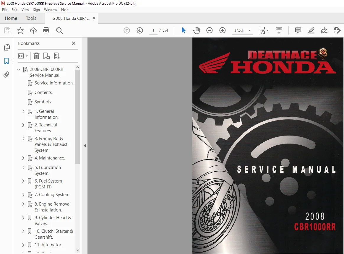
2008 HONDA CBR1000RR SERVICE MANUAL – PDF DOWNLOAD:
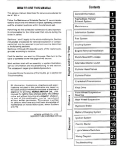
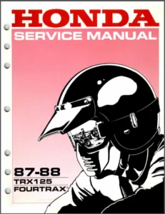
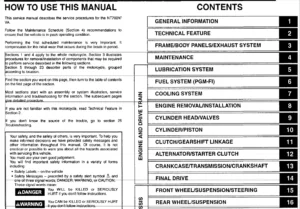
IMAGES PREVIEW OF THE MANUAL:


PLEASE NOTE:
- This is the SAME manual used by the dealers to troubleshoot any faults in your vehicle. This can be yours in 2 minutes after the payment is made.
- Contact us at [email protected] should you have any queries before your purchase or that you need any other service / repair / parts operators manual.
S.V