2008 Land Rover L359 LHD Freelander 2 – LR2 Electrical Circuit Diagrams Manual – PDF DOWNLOAD
$26.95
2008 Land Rover L359 LHD Freelander 2 – LR2 Electrical Circuit Diagrams Manual – PDF DOWNLOAD
VIN: 113897
Part No. JLR 13 86 21_1E,
Description
2008 Land Rover L359 LHD Freelander 2 – LR2 Electrical Circuit Diagrams Manual – PDF DOWNLOAD
FILE DETAILS:
2008 Land Rover L359 LHD Freelander 2 – LR2 Electrical Circuit Diagrams Manual – PDF DOWNLOAD
Language : English
Pages :112
Downloadable : Yes
File Type : PDF
2008 Land Rover L359 LHD Freelander 2 – LR2 Electrical Circuit Diagrams Manual – PDF DOWNLOAD
VIN: 113897
Part No. JLR 13 86 21_1E,
PREFACE
- While every effort is made to ensure accuracy, design changes to the vehicle may be made in the period between the completion of this publication and the introduction of vehicles.
- All rights reserved. No part of this publication may be reproduced, stored in a retrieval system or transmitted in any form, electronic, mechanical, recording or other means without prior written permission from Land Rover.
- Paper copies of this document are uncontrolled, always refer to the electronic source material for the latest information.
USING THIS PUBLICATION
Health and safety
Always follow health and safety guidelines, specifically those detailed in the Workshop Manual.
Using this publication
The information provided in this publication is for use only by competent, qualified auto-electricians. Good product knowledge is
assumed, as well as the ability to access and use recommended test equipment and other reference material provided.
Test equipment and other reference material
The information in this publication should be used in conjunction with the recommended test equipment; refer to Workshop Manual.
Other reference material includes: Technical Service Bulletins (TSB) and the Workshop Manual.
The Electrical Reference Library (ERL) may also prove useful since it provides detailed connector information.
Battery disconnection and reconnection
It is imperative that any information relating to battery disconnection and reconnection is followed; refer to the appropriate sections
in the Workshop Manual.
Fault Diagnosis
Always use the recommended test equipment for correct and reliable fault diagnosis, refer to the Workshop Manual.
Harness Repair
Repairs should only be undertaken for connectors where a Service Repair Kit is available; refer to the appropriate Electrical
Reference Library (ERL).
TABLE OF CONTENTS:
2008 Land Rover L359 LHD Freelander 2 – LR2 Electrical Circuit Diagrams Manual – PDF DOWNLOAD
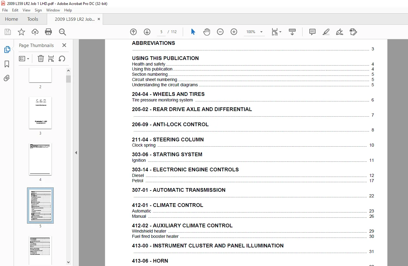
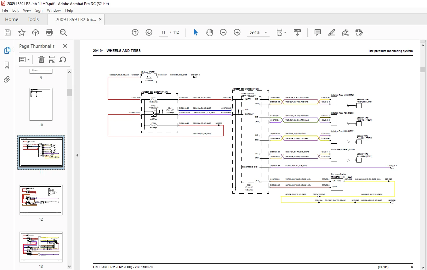
FREELANDER 2 - LR2 - LHD - VIN: 113897 >..............  1
	TITLE PAGE........................................  3
	PREFACE...........................................  4
	CONTENTS..........................................  5
	ABBREVIATIONS.....................................  7
	USING THIS PUBLICATION............................  8
204-04 - WHEELS AND TIRES............................. 11
	Tire pressure monitoring system................... 11
205-02 - REAR DRIVE AXLE AND DIFFERENTIAL............. 12
206-09 - ANTI-LOCK CONTROL............................ 13
211-04 - STEERING COLUMN.............................. 15
	Clock spring...................................... 15
303-06 - STARTING SYSTEM.............................. 16
	Ignition.......................................... 16
303-14 - ELECTRONIC ENGINE CONTROLS................... 17
	Diesel............................................ 17
	Petrol............................................ 22
307-01 - AUTOMATIC TRANSMISSION....................... 27
412-01 - CLIMATE CONTROL.............................. 28
	Automatic......................................... 28
	Manual............................................ 31
412-02 - AUXILIARY CLIMATE CONTROL.................... 34
	Windshield heater................................. 34
	Fuel fired booster heater......................... 35
413-00 - INSTRUMENT CLUSTER AND PANEL ILLUMINATION.... 36
413-06 - HORN......................................... 37
413-08 - INFORMATION AND MESSAGE CENTER............... 38
413-13 - PARKING AID.................................. 40
414-01 - BATTERY, MOUNTING AND CABLES................. 42
	Battery junction box - P6......................... 42
	Central junction box.............................. 45
	Battery junction box - D4......................... 51
	Ground distribution............................... 55
	Auxiliary junction box............................ 60
414-02 - GENERATOR AND REGULATOR...................... 63
	Charging.......................................... 63
415-00 - INFORMATION AND ENTERTAINMENT SYSTEM......... 64
	High line......................................... 64
	Low-line.......................................... 69
417-01 - EXTERIOR LIGHTING............................ 71
	Trailer socket - NAS.............................. 71
	Trailer socket - Europe........................... 72
	Headlamps - high intensity discharge.............. 73
	Headlamps - high intensity discharge.............. 77
	Headlamps - adaptive front lighting system........ 81
417-02 - INTERIOR LIGHTING............................ 83
418-00 - MODULE COMMUNICATIONS NETWORK................ 85
	LIN bus........................................... 85
	CAN bus - high speed.............................. 87
	Diagnostic socket................................. 88
	CAN bus - medium speed............................ 89
419-01 - ANTI-THEFT SYSTEM............................ 90
501-09 - REAR VIEW MIRRORS............................ 92
	Interior.......................................... 92
	Exterior.......................................... 93
501-10 - SEATING...................................... 94
	Memory............................................ 94
	Heated - front.................................... 96
	Heated - front.................................... 98
501-11 - GLASS, FRAMES AND MECHANISMS................. 99
	Window lift....................................... 99
501-12 - INSTRUMENT PANEL AND CONSOLE.................102
501-14 - HANDLES, LOCKS, LATCHES AND ENTRY SYSTEMS....103
	Central locking system............................103
501-16 - WIPERS AND WASHERS...........................106
501-17 - ROOF OPENING PANEL...........................109
501-20 - SUPPLEMENTAL RESTRAINT SYSTEM................110
Published by Technical Communications, Land Rover.....112
Customer Support: [email protected]
IMAGES PREVIEW OF THE MANUAL:
S.M