2011 Harley Davidson Touring Models Service Manual – PDF DOWNLOAD
Original price was: $89.95.$19.95Current price is: $19.95.
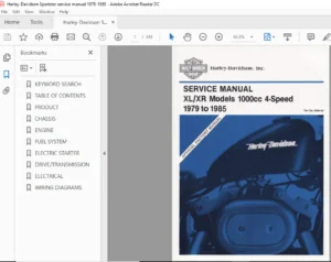
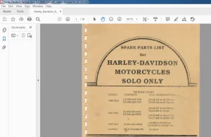
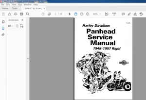
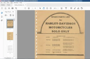
2011 Harley-Davidson Touring Models Service Manual – PDF DOWNLOAD
Description
2011 Harley Davidson Touring Models Service Manual – PDF DOWNLOAD
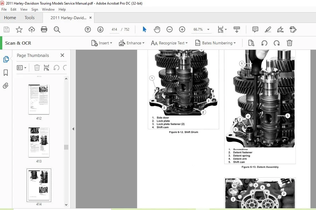
IMAGES PREVIEW OF THE MANUAL:


DESCRIPTION:
2011 Harley-Davidson Touring Models Service Manual – PDF DOWNLOAD
ABOUT THIS MANUAL
GENERAL
This Service Manual has been prepared with two purposes in mind. First, it will acquaint the user with the construction of the Harley-Davidson product and assist in the performance of basic maintenance and repair. Secondly, it will introduce to the professional Harley-Davidson Technician the latest field-tested and factory-approved major repair methods. We sincerely believe that this Service Manual will make your association with Harley-Davidson products more pleasant and profitable.
HOW TO USE YOUR SERVICE MANUAL
Refer to the table below for the content layout of this manual.
NO. CHAPTER
1 Maintenance
2 Chassis
3 Engine
4 Fuel System
5 Drive
6 Transmission
7 Electrical
A Appendix A Connector Repair
B Appendix B Wiring
C Appendix C ABS
D Appendix D Conversions
E Appendix E Glossary
- Use the TABLE OF CONTENTS (which follows this FOREWORD) and the INDEX (at the back of this manual) to quickly locate subjects. Sections and topics in this manual are sequentially numbered for easy navigation.
- For example, a cross-reference shown as 2.1 SPECIFICATIONS refers to chapter 2 CHASSIS, heading 2.1 SPECIFICATIONS.
- For quick and easy reference, all pages contain a section number followed by a page number. For example, page 3-5 refers to page 5 in section 3.
- A number of acronyms and abbreviations are used in this document. See the D.1 GLOSSARY for a list of acronyms, abbreviations and definitions.
TABLE OF CONTENTS:
2011 Harley-Davidson Touring Models Service Manual – PDF DOWNLOAD
MAINTENANCE
1 1 FASTENER TORQUE VALUES
Fastener Torque Values in this Chapter 1-1
1 2 GENERAL
Servicing a New Motorcycle 1-3
Safe Operating Main tenance 1-3
Shop Practices 1-3
Repair Notes 1-3
Safety 1-3
Removing Parts 1-3
Cleaning 1-3
Disassembly and Assembly 1-4
Checking Torques on Fasteners 1-4
Magnetic Parts Trays 1-4
Repair and Replacement Procedures 1-4
Hardware and Threaded Parts 1-4
Threadlocking Agents 1-4
Wiring , Hoses and Lines 1-4
In struments and Gauges 1-4
Bearings 1-4
Bushings 1-4
Gaskets 1-4
Lip-Type Seals 1-4
0-Rings (Pre-Formed Packings) 1-4
Gears 1-5
Shafts 1-5
Part Replacement 1-5
Exhaust System Leakage 1-5
Cleaning 1-5
Part Protection 1-5
Cleaning Process 1-5
Rust or Corrosion Removal 1-5
Bearings 1-5
Tool Safety 1-5
Air Tools 1-5
Wrenches 1-5
Pliers/Cutters/Pry Bars 1-5
Hammers 1-5
Punches/Chisels 1-6
Screwdrivers 1-6
Ratchets and Handles 1-6
Sockets 1-6
Storage Units 1-6
1 3 FUEL AND OIL
Fuel 1-7
Gasoline Blends 1-7
Engine Lubrication 1-7
Winter Lubrication 1-8
1 4 BULB REQUIREMENTS
General 1-9
1 5 MAINTENANCE SCHEDULE
General 1-11
1 6 ENGINE OIL AND FILTER
Checking Oil Level 1-15
Oil Level Cold Check 1-15
Oil Level Hot Check 1-15
Changing Oil and Oil Filter 1-15
1 7 AIR CLEANER AND EXHAUST SYSTEM
Removal 1-17
Installation 1-17
Exhaust System Leak Check 1-17
1 8 TIRES AND WHEELS
General 1-19
Tires 1-19
Tire Replacement 1-19
Inspection 1-19
When To Replace Tires 1-19
Wheel Bearings 1-20
Wheel Spokes 1-20
Identify Wheel Spoke Groups 1-20
Wheel Spoke Adjustment 1-20
1 9 PRIMARY CHAINCASE LUBRICANT
General 1-22
Changing Primary Chaincase Lubricant 1-22
1 10 TRANSMISSION LUBRICANT
Transmission Lubrication 1-24
General 1-24
Check Lubricant Level 1-24
Changing Transmission Fluid 1-24
1 11 CLUTCH (/)
Adjustment 1-26 1-
1 12 DRIVE BELT AND SPROCKETS
General 1-28 z
Cleaning 1-28 0
Inspection 1-28 U
Sprockets 1-28 LL
Drive Belt 1-28 O
Checking Drive Belt Deflection 1-29
Setting Belt Deflection 1-30 W
Adjustment 1-30 ~
ISOLATOR
Inspection 1-33
1 14 CABLE AND CHASSIS LUBRICATION
General 1-34
Steering Head Bearings 1-34
Ji ffy Stand 1-34
Miscellaneous Lubrication 1-34
Hinges, Latches, Etc 1-34
1 15 BRAKES
Fluid Inspection 1-35
1 16 BRAKE PADS AND DISCS
Inspection 1-36
Brake Pads 1-36
Brake Disc Thickness 1-36
Brake Disc Lateral Runout 1-36
Brake Pad Replacement 1-36
Rear Brake Caliper 1-36
Front Brake Calipers 1-38
TABLE OF CONTENTS
1 17 SPARK PLUGS
Inspection 1-40
Spark Plug Cable lnspection 1-40
1 18 FRONT FORK OIL
Replacing Fork Oil 1-42
1 19 SUSPENSION ADJUSTMENTS
General 1-43
1 20 STEERING HEAD BEARINGS
Lubrication 1-45
Checking 1-45
Adjustment 1-46
1 21 HEADLAMP ALIGNMENT
Headlamp Alignment 1-47
Headlamp Adjustment: Single Headlamp Models 1-47
Headlamp Adjustment: Dual Headlamp Models 1-48
Auxiliary Lamp Alignment 1-48
1 22 CRITICAL FASTENERS
Inspection 1-50
Checking Torques on Fasteners 1-50
1 23 BATTERY MAINTENANCE
General 1-52
Cleaning and lnspection 1-53
Battery 1-53
Disconnection and Removal 1-53
Installation and Connection 1-53
Voltmeter Test 1-54
Voltmeter Test 1-54
Charging Battery 1-54
Safety Precautions 1-54
Using a Battery Charger 1-54
Storage 1-55
1 24 ENGINE MOUNTS
Inspection 1-57
General 1-57
Stabilizer Link 1-57
Front Engine Mount 1-57
Rear Frame Fasteners 1-57
1 25 STORAGE
General 1-58
Placing in Storage 1-58
Removal from Storage 1-58
1 26 TROUBLESHOOTING
General 1-60
Engine 1-60
Starter Motor Does Not Operate or Does Not Turn Engine
Over 1-60
Engine Turns Over But Does Not Start 1-60
Starts Hard 1-60
Starts But Runs Irregularly or Misses 1-60
A Spark Plug Fouls Repeatedly 1-61
Pre-Ignition or Detonation (Knocks or Pings) 1-61
IV TABLE OF CONTENTS
Overheating 1-61
Valve Train Noise 1-61
Excessive Vibration 1-61
Check Engine Light Illuminates During Operation 1-61
Lubrication System 1-61
Oil Does Not Return To Oil Reservoir 1-61
Engine Uses Too Much Oil Or Smokes Excessively 1-61
Engine Leaks Oil From Cases, Push Rods, Hoses,
Etc 1-61
Low Oil Pressure 1-62
High Oil Pressure 1-62
Electrical System 1-62
Alternator Does Not Charge 1-62
Alternator Charge Rate Is Below Normal 1-62
Speedometer Operates Erratically 1-62
Transmission 1-62
Shifts Hard 1-62
Jumps Out Of Gear 1-62
Clutch Slips 1-62
Clutch Drags Or Does Not Release 1-62
Clutch Chatters 1-62
Handling 1-62
Irregularities 1-62
Brakes 1-63
Brake Does Not Hold Normally 1-63
CHASSIS
2 1 FASTENER TORQUE VALUES
Fastener Torque Values in this Chapter 2-1
2 2 SPECIFICATIONS
Specifications 2-6
Chassis Specifications 2-6
Tire Specifications 2-7
2 3 VEHICLE IDENTIFICATION NUMBER
(V I N )
Vehicle Identification Number: Touring Models 2-9
2 4 FRONT WHEEL
Removal 2-11
Cleaning and Inspection 2-12
Installation 2-12
2 5 REAR WHEEL
Removal 2-14
Cleaning and Inspection 2-15
Installation 2-15
2 6 REAR WHEEL COMPENSATOR
Isolator Replacement 2-18
Removal 2-18
Installation 2-18
Sprocket Bearing Replacement 2-18
Removal 2-18
Installation 2-18
2 7 WHEEL LACING: FRONT RIM
Wheel Lacing: Angle Flange Hub 2-20
TABLE OF CONTENTS
2 8 WHEEL LACING: 16 INCH REAR RIM 2 15 REAR BRAKE CALIPER
Wheel Lacing: 16 ln Rear Wheel 2-22 Remova l 2-48
Installation 2-48
2 9 CHECKING AND TRUING WHEELS
General 2-25 2 16 BLEEDING BRAKES
Checking Wheel Run out 2-25 General 2-49
Checking Lateral Runout 2-25 Procedure 2-49
Checking Radial Runout 2-25
Laced Wheel Rim Offset 2-25 2 17 FRONT FORK
Truing Laced Wheels 2-27 Changing Fork Oil 2-51
Radial Runout 2-27 Draining 2-51
Lateral Runout 2-28 Filling 2-51
2 10 SEALED WHEEL BEARINGS Removal 2-52
Disassembly 2-52
Inspection 2-29 Cleaning and lnspection 2-54
Removal 2-29 Assembly 2-55
Installation 2-30 Installation 2-55
2 11 TIRES 2 18 STEERING HEAD BEARINGS
General 2-32 Removal 2-57
Removal 2-32 Inspection 2-58
Cleaning, Inspection and Repair 2-32 In stallation 2-59
Installation 2-33
Tube Type Tires 2-33 2 19 REAR AIR SUSPENSION
Tubeless Tires 2-33 Check for Air Leaks 2-60
Checking Tire Runout 2-34 Compression Fitting 2-60
Lateral Runout 2-34 Air Valve Assembly 2-60
Radial Runout 2-34 Air Tubes 2-60
Wheel Balancing 2-35
Weights 2-35 2 20 REAR SHOCK ABSORBERS
2 12 FRONT BRAKE MASTER CYLINDER Removal 2-62
Cleaning and Inspection 2-62
General 2-36 Disassembly and Assembly 2-62
Removal and Disassembly 2-36 Installation 2-62
Removal 2-36
Disassembly 2-36 2 21 REAR FORK
Cleaning and Inspection 2-38
Assembly and lnstallation 2-38
Assembly 2-38
lnstallation 2-38
Front Brake Line: Non-ABS Equipped 2-38
Removal 2-38
Installation 2-39
Removal 2-63
Disassembly and Assembly 2-63
Bearing Removal 2-63
Bearing In stallation 2-64
Pivot Shaft/Mount Disassembly 2-64
Installation 2-65
2 13 FRONT BRAKE CALIPER 2 22 CLUTCH CABLE
Removal 2-41
Installation 2-41
Removal 2-66
Installation 2-66
2 14 REAR BRAKE MASTER CYLINDER 2 23 HANDLEBARS
General 2-42
Removal and Disassembly 2-42
Removal 2-42
Disassembly 2-43
Cleaning and Inspection 2-44
Assembly and Insta llation 2-45
Assembly 2-45
lnstallation 2-45
Rear Brake Line: Non-ABS Equipped 2-45
Removal 2-45
ln stallation 2-46
Adjustment 2-69
Removal 2-69
Installation 2-70
Left Handgrip 2-71
Removal 2-71
Installation 2-71
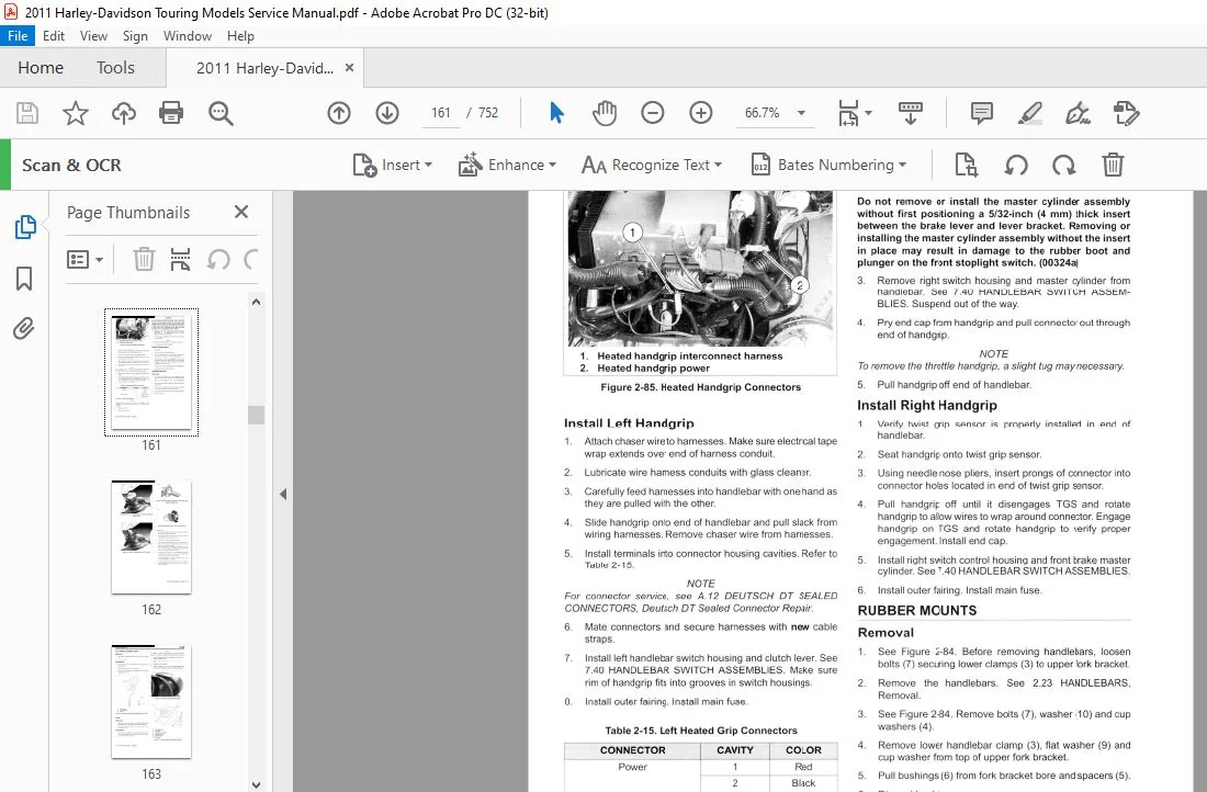
Heated Handgrips 2-71
Remove Left Handgrip 2-71
In stall Left Handgrip 2-72
Remove Right Handgrip 2-72
In sta ll Right Handgrip 2-72
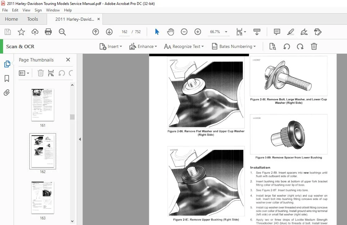
Rubber Mounts 2-72
TABLE OF CONTENTS V
Removal 2-72
In stallation 2-73
2 24 MIRRORS
All Models Except FLHX 2-74
Removal 2-74
Installation 2-7 4
FLHX 2-74
Remova1 2-74
Installation 2-7 4
2 25 SEAT
Seat: Models without Tour-Pak 2-75
Removal 2-75
Installation 2-75
Seat: Models with Tour-Pak 2-75
Remova1 2-75
lnstallation 2-76
Seat: Road King Models 2-76
Removal 2-76
ln stallation 2-76
Seat Retention Nut Replacement 2-76
Seat Bumper 2-77
2 26 SADDLEBAGS
Removal 2-78
lnstallation 2-78
2 27 SADDLEBAG SERVICE
Saddlebag Hardware 2-79
Removal 2-79
ln sta llation 2-80
Saddlebag Guard/Support Rail 2-80
Removal 2-80
Installation 2-80
2 28 TOUR-PAK
Removal/l nstallation 2-82
Removal 2-82
Installation 2-82
Adjustment 2-83
Luggage Rack/Tour-Pak Support 2-83
Removal 2-83
Assembly and Installation 2-83
2 29 TOUR-PAK SERVICE
Lockset 2-84
Removal 2-84
Installation 2-84
Hinges 2-84
Removal 2-84
lnstallation 2-84
Latches/Lockset Catch 2-85
Removal 2-85
lnstallation 2-85
Catches 2-85
Removal 2-85
ln stallation 2-85
Tether 2-85
Removal 2-85
ln stallation 2-85
VI TABLE OF CONTENTS
Tether Brackets 2-86
Removing Tether Bracket from Tour-Pak 2-86
Removing Tether Bracket from Tour-Pak Lid 2-86
Installing Tether Bracket on Tour-Pak Lid 2-86
Installing Tether Bracket on Tour-Pak 2-86
Luggage Rack 2-86
2 30 TOUR-PAK LIGHTS
General 2-87
Side Marker Lights (if equipped) 2-87
Removal 2-87
lnstallation 2-87
Tour-Pak Lights Harness 2-87
Removal 2-87
lnstallation 2-87
Wrap-Around Lights (if equipped) 2-88
Bulb Replacement 2-88
Removal 2-88
lnstallation 2-89
2 31 TOUR-PAK BACKREST
Passenger Backrest 2-90
Removal 2-90
lnstallation 2-90
Rubber Isolators 2-90
Removal 2-90
lnstallation 2-90
Passenger Backrest Flap 2-91
Removal 2-91
Installation 2-91
2 32 TOUR-PAK SPEAKER BOX
Speaker Box 2-92
Removal 2-92
Installation 2-92
2 33 LOWER FAIRING AND ENGINE GUARD
Lower Fairing 2-93
Removal 2-93
Disassembly 2-93
Assembly 2-94
lnstallation 2-94
Serrated Washer Replacement 2-94
Removal 2-94
lnstallation 2-94
Engine Guard 2-94
Removal 2-94
Installation 2-94
2 34 UPPER FAIRING AND WINDSHIELD:
FORK MOUNTED FAIRING MODELS
Outer Fairing and Windshield 2-96
Removal 2-96
lnstallation 2-96
2 35 FAIRING CAP: FORK MOUNTED
FAIRING MODELS
Fairing Cap 2-97
Removal 2-97
lnstallation 2-97
2 36 INNER FAIRING: FORK MOUNTED
FAIRING MODELS
Removal 2-98
Installation 2-1 00
2 37 AIR DEFLECTORS
Air Deflectors 2-1 02
Removal 2-1 02
Installation 2-1 02
Mid-Frame Air Deflectors 2-1 02
Removal 2-1 02
Installation 2-1 02
2 38 UPPER FAIRING AND WINDSHIELD:
FRAME MOUNTED FAIRING MODELS
Windshield 2-1 03
Removal 2-103
Installation 2-1 03
Outer Fairing 2-1 03
Removal 2-103
Installation 2-1 04
2 39 INSTRUMENT BEZEL: FRAME
MOUNTED FAIRING MODELS
Bezel 2-106
Removal 2-106
Installation 2-1 07
2 40 INSTRUMENT NACELLE: FRAME
MOUNTED FAIRING MODELS
Instrument Nacelle 2-1 08
Remova1 2-108
Installation 2-1 09
2 41 INNER FAIRING: FRAME MOUNTED
FAIRING MODELS
Removal 2 -1 10
Disassembly 2- 11 1
Installation 2-112
Outer Fairing 2-112
Inner Fairing 2-112
2 42 GLOVE BOX DOOR AND HINGE:
FRAME MOUNTED FAIRING MODELS
Glove Box Door and Hinge 2-114
Removal 2-114
Installation 2-114
2 43 WINDSHIELD: ROAD KING MODELS
Windshield 2-11 5
Removal 2-115
Installation 2-11 5
Windshield Window 2-11 5
Removal 2-11 5
lnstallation 2-11 6
TABLE OF CONTENTS
2 44 HEADLAMP NACELLE: ROAD KING
MODELS
Removal 2-118
Installation 2-119
2 45 FRONT FENDER
Removal 2 -120
Installation 2-120
2 46 REAR FENDER
Removal 2-121
Fender Repair 2-122
Mounting Hardware 2-122
Lights and Harnesses 2-122
Installation 2-122
2 47 REAR FASCIA
Removal 2-124
Installation 2-124
Stud Plate 2-124
Removal 2-124
In sta llation 2-124
Rear Fascia Lamp 2-124
Removal 2-124
Insta llation 2-124
2 48 REAR FRAME
Rear Frame 2-125
Removal 2-125
Installation 2-126
Thread Repair 2-126
2 49 FOOTBOARDS AND FOOTRESTS
Rider Footboards 2-127
Removal 2-127
Installation 2-127
Disassembly 2-127
Assembly 2-127
Passenger Footboard 2-128
Removal 2-128
Disassembly 2-128
Assembly 2-128
Installation 2-128
Passenger Footrest: FLHX, FLTRX 2-128
Removal 2-128
Disassembly 2-128
Assembly 2-129
In stallation 2-129
2 50 JIFFY STAND
General 2-130
Leg Removal 2-130
Leg In stallation 2-130
Jiffy Stand Bracket 2-131
Removal 2-131
Instal lation 2-131
Jiffy Stand Interlock Sensor 2-131
Removal 2-131
Installa tion 2-132
TABLE OF CONTENTS VII
TABLE OF CONTENTS
2 51 FRONT ENGINE MOUNT 3 13 CAM COMPARTMENT SERVICE
Removal 2-133 Engine in Chassis 3-26
ln stallation 2-133 Engine Removed From Chassis 3-27
ENGINE 3 14 STRIPPING MOTORCYCLE FOR
SERVICE
3 1 FASTENER TORQUE VALUES Proced ure 3-28
Fastener Torque Values in this Chapter 3-1 Cam Compartment Service Only 3-28
3 2 SPECIFICATIONS
Specifications 3-3
3 3 SERVICE WEAR LIMITS
General 3-5
3 4 ENGINE OIL FLOW
Oil Feed 3-7
Top End 3-7
Bottom End 3-9
Oil Return 3-11
Oil Cooler Operation 3-12
3 5 OIL PUMP OPERATION
General 3-1 3
Operation 3-13
3 6 BREATHER OPERATION
General 3-1 5
3 7 OIL PRESSURE
Oil Pressure Indicator Lamp 3-16
Checking Oil Pressure 3-16
3 8 TROUBLESHOOTING
Diagnosing Valve Train Noise 3-18
Compression Test 3-18
Cylinder Leakdown Test 3-19
Diagnosing Smoking Engine or High Oil Consumption 3-19
Check Prior To Cylinder Head Removal 3-19
Check After Cylinder Head Remova1 3-19
3 9 OIL COOLER
Removal 3-20
Installation 3-20
3 10 OIL COOLER ADAPTER
Removal 3-21
Disassembly 3-21
Assembly 3-21
In sta llation 3-21
3 11 HOW TO USE THIS SECTION
Top End Repair 3-23
Bottom End Repair 3-23
Typical Symptoms 3-23
3 12 TOP END SERVICE
Engine in Chassis 3-24
Engine Removed from Chassis 3-25
VIII TABLE OF CONTENTS
Top End Service 3-28
3 15 ASSEMBLING MOTORCYCLE AFTER
SERVICE
Procedure 3-29
After Top End Service 3-29
After Cam Compartment Service 3-29
3 16 REMOVING ENGINE FROM CHASSIS
Procedure 3-30
3 17 INSTALLING ENGINE IN CHASSIS
Procedure 3-31
3 18 TOP END OVERHAUL: DISASSEMBLY
General 3-32
Rocker Covers 3-32
Rocker Arm Support Plate 3-32
Push Rods, Lifters and Covers 3-34
Cylinder Head 3-35
Cylinder 3-36
Piston 3-36
3 19 BREATHER ASSEMBLY
Disassembly 3-38
Early Production 3-38
Late Production 3-38
Cleaning and lnspection 3-38
Assembly 3-38
Early Production 3-38
Late Production 3-38
3 20 ROCKER ARM SUPPORT PLATE
Disassembly 3-40
Cleaning and lnspection 3-40
Inspection 3-40
Rocker Shaft Fit 3-40
Rocker Arm Shaft to Bushing 3-41
Replace Rocker Arm Bushings 3-41
Assembly 3-42
3 21 PUSH RODS, LIFTERS AND COVERS
Disassembly 3-43
Cleaning and Inspection 3-43
Lifter lnspection 3-44
Assembly 3-44
3 22 CYLINDER HEAD
Disassembly 3-45
Cleaning 3-46
Inspection 3-46
Cylinder Head 3-46
Valve Guides 3-47
Valves 3-47
Valve Springs 3-47
Tapered Keepers 3-47
Valve Seats 3-47
Valve Guide Replacement 3-47
Removal 3-4 7
lnstallation 3-48
Valve and Seat Refacing 3-51
Assembly 3-53
3 23 CYLINDER
Cleaning 3-56
Inspection 3-56
Deglazing Cylinder 3-58
Boring and Honing Cylinder 3-58
3 24 PISTON
Disassembly 3-60
Piston Rings 3-60
Cleaning 3-60
Inspection 3-60
Assembly 3-62
Checking Piston Ring Gap 3-62
Installing Piston Rings 3-62
3 25 TOP END OVERHAUL: ASSEMBLY
General 3-64
Piston 3-64
Cyl inder 3-65
Cylinder Head 3-67
Push Rods, Lifters and Covers 3-71
Rocker Arm Support Plate 3-72
Breather and Rocker Cover 3-73
3 26 CAM COMPARTMENT AND
COMPONENTS
Cam Support Plate and Cover Removal 3-75
Prepare Engine 3-75
Cam Chain and Sprockets Removal 3-75
Cam Support Plate Removal 3-76
Cam Support Plate Cleaning and lnspection 3-77
Oil Pressure Valve 3-77
Cam Support Plate 3-77
Camshafts 3-77
Removal 3-77
Insta llation 3-78
Oil Pressure Relief Va lve 3-79
Removal 3-79
Inspection 3-79
In stallation 3-79
Cam Needle Bearings 3-80
Removal 3-80
In sta llation 3-81
Cam Support Plate and Cover Installation 3-83
3 27 OIL PUMP
Removal 3-87
Clean ing and Inspection 3-87
Installation 3-88
TABLE OF CONTENTS
3 28 CRANKCASE DISASSEMBLY AND
REPAIR
Crankcase Disassembly 3-89
Cleaning and Inspection 3-89
Right Crankcase Half 3-90
Main Bearing Removal 3-90
Main Bearing In stal lation 3-90
Piston Jets Remova\ 3-91
Piston Jets ln stallation 3-91
Left Crankcase Half 3-91
Main Bearing Removal 3-91
Main Bearing lnsta llation 3-93
Sprocket Shaft Bearing Inner Race 3-93
Removal 3-93
Installation 3-94
Cylinder Studs 3-96
Removal 3-96
lnstallation 3-96
Pipe Plug and Oil Fittings 3-97
Removal 3-97
Installation 3-97
3 29 FLYWHEEL AND CONNECTING RODS
Inspection 3-98
Measuring Crankshaft Run out 3-98
Crankshaft Removed 3-98
3 30 CRANKCASE ASSEMBLY
Crankcase Assembly 3-1 00
3 31 OIL PAN
Removal 3-1 02
Installation 3-1 02
FUEL SYSTEM
4 1 FASTENER TORQUE VALUES
Fastener Torque Values in this Chapter 4-1
4 2 SPECIFICATIONS: FUEL SYSTEM
Specifications 4-3
4 3 ELECTRONIC FUEL INJECTION (EFI)
Troubleshooting 4-4
4 4 AIR CLEANER ASSEMBLY
Remova l 4-5
In stallation 4-6
4 5 FUEL TANK
Removal 4-8
Purge and Disconnect Fuel Line 4-8
Remove Tank 4-8
Installation 4-8
Evaporative Emissions Tube: Non-CA Models 4-9
Removai A-9
In sta llation 4-9
Fuel Supply Check Valve/Tube 4-9
Removal 4-9
Install ation 4-1 0
TABLE OF CONTENTS IX
TABLE OF CONTENTS
4 6 FUEL TANK TOP PLATE
Removal 4-11
Installation 4-12
4 7 FUEL FILTER
Removal 4-13
lnstallation A-13
4 8 FUEL PRESSURE REGULATOR
Removal 4-14
Installation 4-14
4 9 FUEL LEVEL SENDER
Removal 4-15
lnstallation A-15
4 10 TWIST GRIP SENSOR
Removai A-16
Installation 4-17
Twist Grip Sensor Jumper Harness A-18
Removal 4-18
Installation 4-18
4 11 THROTTLE CONTROL ACTUATOR
(TCA)
General 4-19
4 12 ENGINE TEMPERATURE SENSOR (ET)
Removal 4-20
Installation 4-20
4 13 INDUCTION MODULE
Removal 4-21
Installation 4-22
4 14 TEMPERATURE MANIFOLD ABSOLUTE
PRESSURE SENSOR (TMAP)
General 4-23
Removal 4-23
Installation 4-23
4 15 OXYGEN SENSORS (02)
General 4-24
Removai A-24
lnstallation A-24
4 16 FUEL INJECTORS
Generai A-26
Removal 4-26
Installation 4-26
4 17 FUEL PUMP
General 4-28
Removai A-28
Installation 4-28
Fuel Pump and Fuel Level Sender Wire Harness 4-29
Removai A-29
lnstallation A-29
X TABLE OF CONTENTS
4 18 FUEL PRESSURE TEST
Generai A-30
Testing A-30
4 19 EXHAUST SYSTEM
Mufflers 4-32
Removai A-32
lnstallation A-32
System Removal 4-32
System Installation 4-33
4 20 ACTIVE EXHAUST (HOI)
Exhaust Valve Actuator 4-35
Removai A-35
Installation 4-35
Exhaust Valve Actuator Cable A-35
Removai A-35
Installation 4-35
Active Exhaust Valve A-35
General 4-35
4 21 INTAKE LEAK TEST
Generai A-36
Leak Tester A-36
Parts List 4-36
Tester Assembly 4-36
Tester Adjustment A-36
Procedure 4-36
4 22 EVAPORATIVE EMISSIONS CONTROL
SYSTEM
Generai A-38
Vapor Valve A-38
Fuel Vapor Vent Tube 4-39
Removal 4-39
Installation 4-39
Canister-to-Solenoid Tube 4-39
Removai A-39
lnstallation A-39
Solenoid-to-Induction Module Tube 4-39
Removal 4-39
Installation 4-39
Purge Solenoid 4-40
Removai A-40
Installation 4-40
Charcoal Canister 4-40
Removai A-40
lnstallation A-40
DRIVE
5 1 FASTENER TORQUE VALUES
Fastener Torque Values in this Chapter 5-1
5 2 SPECIFICATIONS: DRIVE
Specifications 5-2
5 3 PRIMARY CHAINCASE COVER
Genera1 5-3
Removal 5-3
Installation 5-3
5 4 DRIVE COMPONENTS
Removal 5-5
Installation 5-7
5 5 PRIMARY CHAINCASE HOUSING
Removal 5-10
Inspection 5-1 0
Mainshaft Bearing and Lip Seal 5-10
Removal 5-10
lnstallation 5-1 0
Mainshaft Bearing Inner Race 5-11
Removal 5-11
Installation 5-12
Shifter Shaft Bushings 5-12
Installation 5-12
5 6 CLUTCH
Removal and lnstallation 5-14
Clutch Pack Only 5-14
Partial Disassembly 5-14
Cleaning And lnspection 5-14
Assembly 5-15
Clutch Pack and Bearing 5-16
Complete Disassembly 5-16
Assembly 5-17
5 7 TRANSMISSION SPROCKET
Removal 5-19
Cleaning and Inspection 5-19
Installation 5-19
5 8 DRIVE BELT
Removal and Adjustment 5-21
Adjustment 5-21
Removal 5-21
Installation 5-21
TRANSMISSION
6 1 FASTENER TORQUE VALUES
Fastener Torque Values in this Chapter 6-1
·6 2 SPECIFICATIONS: TRANSMISSION
Specifications 6-2
Service Wear Limits 6-2
6 3 TRANSMISSION
Power Flow 6-3
Neutral 6-3
1st Gear 6-3
2nd Gear 6-3
3rd Gear 6-3
4th Gear 6-3
5th Gear 6-3
6th Gear 6-3
6 4 SHIFTER LINKAGE
Shifter Rod 6-5
TABLE OF CONTENTS
6 5 CLUTCH RELEASE COVER
Removal and Disassembly 6-6
Cleaning and lnspection 6-6
Assembly and lnstallation 6-7
6 6 TRANSMISSION ASSEMBLY
Removal 6-8
Disassembly 6-9
Shifter Cam/Shifter Forks 6-9
Mainshaft 6-11
Countershaft 6-13
Removing Side Door Bearings 6-14
Cleaning and Inspection 6-15
Assembly 6-15
Installing Side Door Bearings 6-15
Countershaft 6-15
Mainshaft 6-16
Shifter Cam/Shifter Forks 6-16
Installation 6-18
6 7 MAIN DRIVE GEAR AND BEARING
Removal 6-20
Cleaning and lnspection 6-21
Needle Bearing Replacement 6-22
Mainshaft Seal Replacement 6-23
Installation 6-24
Installing Main Drive Gear Bearing 6-24
Installing Main Drive Gear 6-24
Install ing Main Drive Gear Large Seal 6-25
6 8 TRANSMISSION CASE
Remova l 6-27
Installation : 6-27
Disassembly 6-28
Shifter Arm Assembly 6-28
Cleaning and Inspection 6-28
Assembly 6-29
Countershaft Needle Bearing Replacement 6-29
Shifter Pawl Lever Assembly 6-29
ELECTRICAL
7 1 FASTENER TORQUE VALUES
Fastener Torque Values in this Chapter 7-1
7 2 SPECIFICATIONS: ELECTRICAL
Specifications 7-5
7 3 VOLTAGE REGULATOR
Removal 7-6
Installation 7 -6
7 4 ELECTRONIC CONTROL MODULE (ECM)
ECM 7-7
Removal 7-7
Installation 7 -7
7 5 TURN SIGNAL AND SECURITY MODULE
(TSM/TSSM/HFSM)
General ?-8
TABLE OF CONTENTS XI
TABLE OF CONTENTS
Removal ?-8 Removal ?-23
Installation 7 -8 Repair ? -23
HFSM Antenna ?-8 Installation ? -23
Removal ?-8 Headlamp Bulb Replacement: Dual Headlamp Models 7-23
In stallation 7 -9 Removal 7 -23
7 6 IGNITION COIL
Bulb Replacement 7 -23
Installation ? -24
Removal 7-1 0
Installation ? -10 7 13 AUXILIARY LAMPS AND BRACKETS
7 7 SYSTEM FUSES AND RELAYS
Auxiliary Lamp Bulb Replacement ?-25
Removal ?-25
Main Fuse ? -11 Installation ? -25
Removal ?-11 Auxiliary Lamp Housing ?-26
Installation 7 -11 Removal ? -26
Main Fuse Holder ?-11 Installation 7 -27
Removal ?-11 Auxiliary Lamp Bracket ?-27
Installation ? -11 Removal ? -27
System Fuses and Relays ?-11 Installation ? -28
Removal ?-11 Adjustment ? -28
lnstallation ?-11
Fuse Blocks ? -12 7 14 TAIL LAMP
Removal ?-12 Tail Lamp Bulb Replacement ?-29
Installation ? -12 Removal ?-29
7 8 ELECTRICAL CADDIES
In stallation ? -29
Circuit Board/Chrome Base 7 -29
Top Caddy 7 -13 Removal ?-29
Removal ?-1 3 Instal lation 7-30
Installation ? -1 3 Rear Fender Lights Harness: all except FLHX, FL TRX 7-30
Left Side Caddy ? -13 Removal ?-30
Removal ?-1 3 Installation ? -31
In stallation ? -13 Rear Fender Lights Harness: FLHX, FLTRX ?-32
Battery Tray ? -15 Removal 7-32
Removal 7 -15 In stal lation 7-32
In stall ation ? -1 6 7 15 FENDER TIP LAMPS
7 9 SECURITY SIREN Front Fender Tip Lamp 7-34
Removal ?-17 Removal ?-34
Installation 7 -17 In stall ation 7 -34
Front Fender Tip Lamp Jumper Harness ?-34
7 10 STARTER Removal ?-34
General ?-18
Removal 7-1 8
Drive Assembly ?-1 8
Disassembly ? -18
lnstallation ?-35
Rear Fender Tip Lamp ?-36
Removal ?-36
In stallation ? -37
Inspection 7-19
Assembly ?-19
7 16 TURN SIGNAL LAMPS
Solenoid 7-20 Turn Signal Bulb Replacement: Bullet Style 7-38
Cover and Plunger Removal ?-20 Turn Signal Bulb Replacement: Flat Lens Style ?-38
Short Post Contact: Starter ?-20 Front Turn Signal Lamp ?-38
Long Post Contact: Battery Positive 7 -20 Removal: Flat Lens Style ?-38
Plunger and Cover Installation 7 -21 Installation: Flat Lens Style ? -39
Installation 7 -21 Removal: Bullet Style, Fork Mounted ?-40
Installation: Bullet Style, Fork Mounted 7 -41
7 11 HEADLAMP: ALL EXCEPT ROAD GLIDE Removal: Bullet Style, Fairing Mounted l-41
Headlamp: Single Headlamp Models ?-22
Removal ? -22
Bulb Replacement 7 -22
In stallation 7 -22
Insta llation: Bullet Style, Fairing Mounted ?-42
Rear Turn Signal Lamp ?-42
Removal: FLHR/C, FLHTC/U, FLHTK ?-42
Installation: FLHR/C, FLHTC/U, FLHTK ?-43
Removal: FLHX, FLTRX, FLTRU ?-43
7 12 HEADLAMP: ROAD GLIDE Instal lation: FLHX, FLTRX, FLTRU ?-43
Head lamp Adjuster Assembly 7-23
Rear Turn Signal Lamps Bracket ?-45
Removal: FLHR/C, FLHTC/U, FLHTK ?-45
XII TABLE OF CONTENTS
Instal lation: FLHR/C, FLHTC/U, FLHTK ?-45
Removal: FLHX, FLTRX, FLTRU ?-45
Installation: FLHX, FLTRX, FLTRU ?-46
7 17 IGNITION/LIGHT KEY SWITCH AND
FORK LOCK
Fairing Models 7 -4 7
Remova l ?-47
In stallation ? -49
Road King Models ?-50
Ignition/Light Key Switch: Removal ?-50
Ignition/Light Key Switch: Installation 7 -50
Fork Lock: Removal ?-50
Fork Lock: In stal lation 7 -50
7 18 FAIRING CAP SWITCHES: FORK
MOUNTED FAIRING MODELS
Removal ?-51
Installation 7-51
7 19 1NSTRUMENT NACELLE SWITCHES:
FRAME MOUNTED FAIRING MODELS
Removal 7-53
Left Side Switch ?-53
Right Side Switches ?-54
lnstallation ?-54
Left Side Switch ?-54
Right Side Switches 7-54
7 20 CRANKSHAFT POSITION SENSOR
(CKP)
General ?-57
Removal 7-57
Installation 7-57
7 21 AUTOMATIC COMPRESSION RELEASE
(ACR)
General ?-58
Removal ?-58
Installation 7-58
7 22 ALTERNATOR
Removal 7-60
Cleaning and lnspection ?-60
Installation 7 -61
7 23 VEHICLE SPEED SENSOR (VSS)
VSS 7-62
Removal ? -62
Installation 7-62
7 24 NEUTRAL SWITCH
Removal 7-63
Installation 7 -63
7 25 OIL PRESSURE SWITCH AND SENDER
Removal 7-64
Installation 7 -64
TABLE OF CONTENTS
7 26 STOPLIGHT SWITCHES
Front Stoplight Switch ?-65
Removal /! nstallation 7-65
Rear Stoplight Switch ?-65
Removal ?-65
Installation 7-65
7 27 HORN
Inspection 7-66
Removal 7-66
Installation 7 -66
7 28 CIGARETTE LIGHTER: FAIRING
MODELS
Troubleshooting 7 -67
Removal 7-67
Installation 7 -67
7 29 GAUGES AND INSTRUMENTS: FAIRING
MODELS
2 Inch Diameter Gauges: Fuel Level, Ambient Air Temperature,
Voltmeter, Oil Pressure ?-68
Removal ?-68
Installation 7 -68
Tachometer 7-68
Removal ?-68
Installation 7 -68
Speedometer 7-69
Removal 7 -69
Insta llation 7-69
7 30 INDICATOR LAMPS: FAIRING MODELS
Indicator Lamps ? -70
Removal ?-70
Installation 7 -70
7 31 GAUGES AND INSTRUMENTS: ROAD
KING MODELS
Fuel Gauge ?-71
Removal ?-71
Installation 7-71
Speedometer 7 -71
Removal 7-71
In stallation 7 -72
7 32 INDICATOR LAMPS: ROAD KING
MODELS
lndicalor Lamps ?-73
Removal ?-73
Insta llation 7-73
7 33 ADVANCED AUDIO SYSTEM
Radio ?-74
Removal ?-74
Installation 7-7 4
Front Fairing Speakers 7 -75
Removal ?-75
Installation 7 -75
Front Headset Receptacle ?-75
TABLE OF CONTENTS XII I
TABLE OF CONTENTS
Removal ?-75
Installation ? -75
Rear Headset Receptacle ?-76
Rear Passenger Switches ?-76
Removal ?-76
Installation ? -76
Rear Speakers 7-77
Removal ?-77
lnstallation ?-77
CB Module ?-78
Removal ?-78
Installation 7-78
7 34 WIRE TROUGH
Removal ?-79
Installation ? -80
7 35 MAIN WIRING HARNESS
Removal: All Models (Part 1) 7-81
Removal: Road King Models (Part 2) 7-81
Removal: Fork Mounted Fairing Models (Part 2) 7-82
Removal: Frame Mounted Fairing Models (Part 2) 7-83
Removal: All Models (Part 3) 7-83
Installation: All Models (Part 1 ) ? -85
Installation: Road King Models (Part 2) 7-87
Installation: Fork Mounted Fairing Models (Part 2) 7-88
Installation: Frame Mounted Fairing Models (Part 2) 7-88
Installation: All Models (Part 3) 7 -88
7 36 INTERCONNECT HARNESS
Fork Mounted Fairing Models ?-89
Removal ?-89
Installation ? -90
Frame Mounted Fairing Models ?-92
Removal ?-92
Installation ? -94
7 37 RADIO ANTENNA CABLE
Models Equipped with Tour-Pak ?-96
Removal ?-96
Installation ? -96
Models without Tour-Pak ?-97
Removal ?-97
Installation ? -97
7 38 REAR AUDIO HARNESS: ULTRA
MODELS
Removal 7-99
Installation ? -99
7 39 CB ANTENNA CABLE: ULTRA MODELS
Removal ?-101
Installation ? -101
7 40 HANDLEBAR SWITCH ASSEMBLIES
Removal 7-103
Right Handlebar Controls ? -103
Left Handlebar Controls ?-103
Disassembly ? -103
Right Side Handlebar Switches ?-103
Left Side Handlebar Switches ? -104
XIV TABLE OF CONTENTS
Specific Repair Procedures: Upper Switch Housings ?-104
Right Side Handlebar (All Models) ?-104
Left Side Handlebar (All Models) 7-1 05
Specific Repair Procedures: Right Side Lower Switch
Housings 7-1 06
Preliminary Instructions ? -106
Turn-Right Signal Switch (All Models) ?-106
Front Stoplight Switch (All Models) ?-106
Mode Select Switch (Classic and Ultra Models) ?-106
Cruise Set/Resume Switch (Road King Classic and Ultra
Models) 7-1 07
Final Instructions ? -108
Specific Repair Procedures: Left Side Lower Switch
Housings 7-1 09
Preliminary Instructions 7-109
Turn-Left Signal Switch (All Models) ?-109
Clutch Interlock Switch 7-1 09
Audio Control Switch (Classic and Ultra Models) ?-111
CB Push-To-Transmit Switch (Ultra Models) ?-111
Cruise On/Off Switch (Road King Classic Models) ?-111
Final Instructions ? -112
General Repair Procedures ?-112
Assembly: Right Side Handlebar Switches 7-113
Assembly: Left Side Handlebar Switches ?-114
lnstallation ?-114
Right Handlebar Controls ?-114
Left Handlebar Controls ?-115
7 41 TSSM/HFSM MAINTENANCE
General 7-119
Fob Battery ?-119
Battery Replacement Schedule ?-119
Battery Replacement 7-119
Smart Siren (If Installed) ? -119
Battery Replacement Schedule ?-119
Battery Replacement ? -119
7 42 PERSONAL IDENTIFICATION NUMBER
(PIN)
General ?-121
Initial Pin Entry ?-121
Changing the Pin ?-121
Modifying an Existing Pin ? -121
7 43 H-DSSS ACTUATION
General 7-123
Sidecar Configuration 7-123
Actuation 7-123
Fob Assignment 7-123
Power Disruption and Configuring ?-123
7 44 TSM/HFSM: PASSWORD LEARN
General 7-124
Password Learn ? -124
APPENDIX A CONNECTOR REPAIR
A 1 AUTOFUSE UNSEALED ELECTRICAL
CONNECTORS
Autofuse Unsealed Connector Repair A-1
General A-1
Disassembly A-1
Assembly A-1
A 2 DELPHI 1 OOW MICRO-PACK SEALED
CONNECTOR
Delphi 1 OOW Micro-Pack Sealed Connector Repair A-2
General A-2
Separating Socket Housing From ECM A-2
Mating Socket Housing To ECM A-2
Removing Socket Terminal A-2
Installing Socket Terminal A-2
Crimping Te rminals A-2
A 3 DELPHI150 METRI-PACK SEALED
CONNECTORS
Delphi 150 Metri-Pack Sealed Connector Repair A-4
Generai A-4
Separating Pin and Socket Housings A-4
Mating Pin and Socket Housings A-4
Removing Socket Terminal A-4
Inserting Socket Terminal A-4
A 4 DELPHI 280 METRI-PACK UNSEALED
CONNECTORS
Fuse Block Repair A-6
Removing Socket Terminals A-6
In stalling Socket Terminals A-6
Crimping Terminals A-6
A S DELPHI 480 METRI-PACK UNSEALED
CONNECTORS
Delphi 480 Metri-Pack Unsealed Connector Repair A-7
Generai A-7
Separating Pin and Socket Housings A-7
Mating Pin and Socket Housings A-7
Removing Socket Terminals A-7
Installing Socket Terminals A-7
A 6 DELPHI 630 METRI-PACK UNSEALED
CONNECTORS
Delphi 630 Metri-Pack Unsealed Connector Repair A-8
Separating Pin and Socket Housings A-8
Mating Pin and Socket Housings A-8
Removing Socket Terminai A-8
Installing Socket Terminai A-8
A 7 DELPHI800 METRI-PACK SEALED MAIN
FUSE HOUSING
Delphi 800 Metri-Pack Sealed Main Fuse Housing
Repair A-9
Removing Socket Terminals A-9
Installing Socket Terminals A-9
A 8 DELPHI METRI-PACK TERMINAL
REPAIR
Metri-Pack Terminal Crimps A-10
Matching Terminal To Crimper A-10
Preparing Wire Lead A-1 0
TABLE OF CONTENTS
Crimping Wire Core A-10
Crimping lnsulation/Seai A-1 0
Inspecting Crimps A-11
A 9 DELPHI MICRO 64 SEALED
CONNECTORS
Delphi Micro 64 Sealed Connector Repair A-12
Generai A-12
Separating Pin and Socket Housings A-12
Mating Pin and Socket Housings A-12
Removing Terminal A-12
Installing Terminal A-13
Preparing Wire Leads for Crimping A-13
Crimping Terminals A-13
Inspecting Crimps A-13
A 10 DELPHI GT 150 SEALED
CONNECTORS
Delp hi GT 150 Sealed Connector Repair A-15
Generai A-15
Separating Pin and Socket Housings A-15
Mating Pin and Socket Housings A-15
Removing Socket Terminals A-15
Installing Socket Terminals A-15
A 11 DELPHI GT 280 SEALED 73-TERMINAL
ECM CONNECTOR
Delphi GT 280 Sealed 73-Terminal ECM Connector A-17
Separating Socket Housing From ECM A-17
Mating Socket Housing To ECM A-17
Socket Terminal A-17
ECM Ground Terminal A-17
A 12 DEUTSCH DT SEALED CONNECTORS
Deutsch DT Sealed Connector Repair A-19
Generai A-1 9
Separating Pin and Socket Housings A-1 9
Mating Pin and Socket Housings A-19
Removing Socket Terminals A-19
Installing Socket Terminals A-19
Removing Pin Terminals A-21
Installing Pin Terminals A-21
Crimping Terminals A-22
A 13 DEUTSCH DT SEALED TERMINAL
REPAIR
Deutsch DT Sealed Terminal Crimps A-23
Preparing Wire Leads for Crimping A-23
Crimping Terminal to Lead A-23
Inspecting Crimps A-23
A 14 DEUTSCH DTM SEALED MINI
TERMINAL REPAIR
Deutsch DTM Sealed Mini Terminal Crimps A-24
Preparing Wire Leads for Crimping A-24
Crimping a Mini Terminal to Wire Lead A-24
Inspecting Crimps A-24
TABLE OF CONTENTS XV
TABLE OF CONTENTS
A 15 DEUTSCH DTM SEALED SOLID
BARREL MINI TERMINAL REPAIR
Deutsch DTM Sealed Solid Barrel Terminal Crimps A-25
Preparing Wire Leads For Crimping A-25
Adjusting Crimper Tool A-25
Crimping a Barrel Contact To Wire Lead A-25
Inspecting Crimps A-25
A 16 JAE MX19 SEALED CONNECTORS
JAE MX 19 Sealed Connectors A-27
Connector Housings A-27
Removing Terminals A-27
Installing Terminals A-27
A 17 MOLEX CMC SEALED CONNECTORS
Mol ex CMC Sealed Connectors A-28
Separating the Connector A-28
Removing Terminals A-28
Installing Terminals A-28
A 18 MOLEX MX 150 SEALED
CONNECTORS
Molex MX 150 Sealed Connector Repair A-30
Separating Pin and Socket Housings A-30
Mating Pin and Socket Housings A-30
Removing Terminals A-30
Installing Terminals A-30
Crimp Terminal to Lead A-31
Prepare Lead A-31
Prepare Tooi A-31
Position Terminal in the Punch/Die A-32
Insert Stripped Lead A-32
Crimp Terminal to Lead A-32
Inspect Crimp A-33
A 19 TYCO 070 MULTILOCK UNSEALED
CONNECTOR
Tyco 070 Multi lock Unsealed Connector Repair A-34
Generai A-34
Separating Pin and Socket Housings A-34
Mating Pin and Socket Housings A-34
Removing Terminals from Housing A-34
Inserting Terminals into Housing A-35
Preparing Wire Leads for Crimping A-35
Crimping Terminals to Leads A-36
Inspecting Crimped Terminals A-37
A 20 SEALED SPLICE CONNECTORS
Sealed Splice Connector Repair A-38
Generai A-38
Preparing Wire Leads A-38
Splicing Wire Leads A-38
Inspecting Seals A-38
APPENDIX B WIRING
B 1 CONNECTORS
Connector Locations B-1
Function/Location B-1
XVI TABLE OF CONTENTS
Place and Color B-1
Connector Number B-1
Repair lnstructions B-1
B 2 WIRING DIAGRAMS
Wiring Diagram lnformation B-7
Wire Color Codes B-7
Wiring Diagram Symbols B-7
2011 Touring Wiring Diagrams B-9
APPENDIX CABS
C 1 FASTENER TORQUE VALUES
Fastener Torque Values in this Chapter C-1
C 2 ABS MODULE
Hydraulic Control Unit (HCU) C-2
Removai C-2
Installation C-3
Electronic Control Unit (ECU) C-3
Removai C-3
Installation C-4
C 3 WHEEL SPEED SENSORS
Front Wheel Speed Sensor C-5
Removai C-5
Installation C-5
Rear Wheel Speed Sensor C-6
Removai C-6
Installation C-6
C 4 ABS BRAKE LINES
Front Master Cylinder to ABS Module C-7
Removai C-7
Installation C-8
ABS Module to Front Brake Calipers C-8
Removai C-8
lnstallation C-9
Rear Master Cylinder to ABS Module C-10
Removal C-1 0
Installation C-11
ABS Module to Rear Brake Caliper C-12
Removal C-12
Installation C-12
APPENDIX D CONVERSIONS
D 1 METRIC CONVERSION
Conversion Table D-1
D 2 FLUID CONVERSIONS
United States System D-2
Metric System D-2
British Imperial System D-2
D 3 TORQUE CONVERSIONS
United States System D-3
Metric System D-3
TABLE OF CONTENTS
APPENDIX E GLOSSARY REFERENCE MATERIAL
E 1 GLOSSARY TOOLS I
Acronyms and Abbreviations E-1 TORQUE VALUES VII
INDEX XXIII
TABLE
2011 HARLEY DAVIDSON TOURING MODELS SERVICE MANUAL – PDF DOWNLOAD:
PLEASE NOTE:
- This is the SAME exact manual used by your dealers to fix your vehicle.
- The same can be yours in the next 2-3 mins as you will be directed to the download page immediately after paying for the manual.
- Any queries / doubts regarding your purchase, please feel free to contact [email protected]
S.V