2011 MG6 Service Manual – PDF Download
Original price was: $85.00.$34.95Current price is: $34.95.
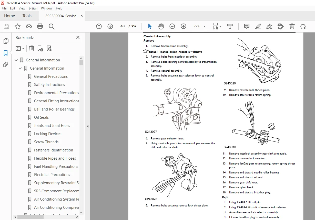
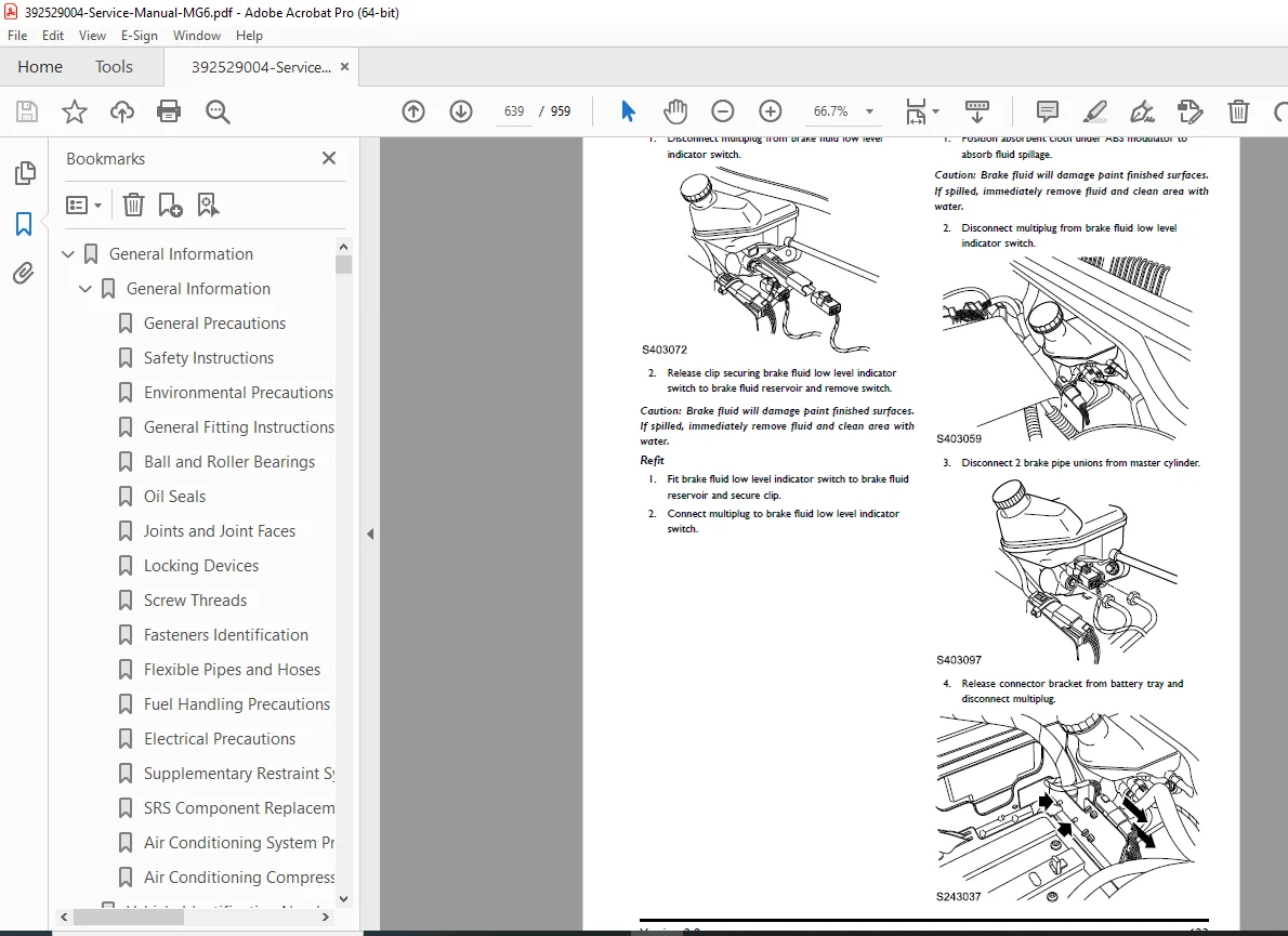
Download the detailed 2011 mg6 service manual pdf download for expert repairs on your compact sedan. This comprehensive mg6 automatic transmission repair guide includes torque specs, fluid changes, and shift diagnostics, while the 2011 mg6 engine mechanical overhaul manual covers timing belt replacement, piston inspections, and cylinder head service. Features mg6 clutch system service procedures for bleeding and master cylinder removal, plus 2011 mg6 hvac system description and operation for refrigerant handling. Essential for technicians tackling mg6 srs safety restraint system diagnostics and ensuring reliable performance with genuine MG guidelines.
Description
2011 MG6 Service Manual – PDF Download
IMAGES:
Description
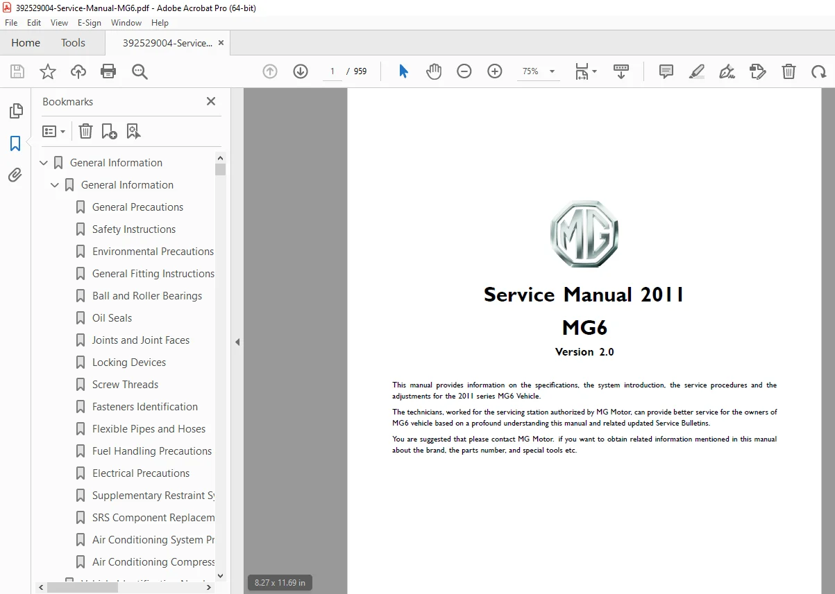
The 2011 mg6 service manual pdf download (Version 2.0) is the official technical resource from MG Motor for servicing the 2011 MG6 series vehicles, providing specifications, system introductions, service procedures, and adjustments. Cutoff date August 2011, it emphasizes using genuine parts and contacting MG for updates on brands, part numbers, and special tools to avoid unauthorized modifications. Ideal for authorized technicians delivering optimal maintenance and repairs.

Key sections like the mg6 automatic transmission repair guide detail pressure tests, inhibitor switches, and torque converter removal, while the 2011 mg6 engine mechanical overhaul manual includes camshaft timing, bearings, and fuel management. Follow mg6 clutch system service procedures for assembly and bleeding, explore 2011 mg6 hvac system description and operation for component layouts and controls, and use mg6 srs safety restraint system diagnostics for airbag module and sensor checks.
Table of Contents (Categorized from Extracted Demo Content; Note: This is partial as the source is a demo PDF with fragmented sections primarily from later pages. Full manual may include earlier systems like General Information, Suspension, Brakes, etc.):
| Section | Subsections | Page Numbers |
|---|---|---|
| Transmission | ||
| Shift Lock Control-MT | 351 | |
| – Specifications | 351 | |
| – Torque | 351 | |
| – Service Procedures | 352 | |
| – Knob–Gear Lever–Manual | 352 | |
| – Remote Control–Gear Change–Manual | 352 | |
| Transmission-AT | 353 | |
| – Specifications | 353-354 | |
| – Torque | 353 | |
| – Description and Operation | 356 | |
| – System Component Layout | 356 | |
| – System Control System | 361 | |
| – Description | 364 | |
| – Operation | 370 | |
| – Service Procedures | 386 | |
| – Automatic transmission–Pressure Test | 386 | |
| – Neutral start (inhibitor)–Switch | 386 | |
| – Neutral Start (Inhibitor)–Switch–Check and Adjust | 388 | |
| – Transmission and Converter | 388 | |
| – Automatic Transmission Fluid–Drain and Refill | 389 | |
| – Automatic Transmission–Top Up | 390 | |
| – Control Unit–Automatic Transmission | 391 | |
| – Harness–Automatic Transmission | 392 | |
| – Sensor–Speed Input | 393 | |
| – Sensor–Speed Output | 393 | |
| – Dipstick–Oil Level | 394 | |
| – Oil Seal–Differential–LH | 394 | |
| – Oil Seal–Differential–RH | 395 | |
| – Torque Converter | 396 | |
| – Side Cover | 397 | |
| – Oil Seal–Oil Pump | 398 | |
| – Special Tools | 399 | |
| Transmission-MT | 400 | |
| – Specifications | 400-401 | |
| – Torque | 400 | |
| – Description and Operation | 402 | |
| – System Component Layout | 402 | |
| – Description | 409 | |
| – Operation | 410 | |
| – Service Procedures | 411 | |
| – Oil Seal–Gear Change Rod | 411 | |
| – Lubrication System–Drain & Refill | 412 | |
| – Manual Transmission Assembly | 412 | |
| – Lamp Switch–Reverse | 416 | |
| – Cover–Reverse Access–Reseal | 416 | |
| – Lubrication System–Manual Transmission–Top up | 417 | |
| – Oil Seal–Differential–LH | 417 | |
| – Oil Seal–Differential–RH | 418 | |
| – Manual Transmission Dismantling | 418 | |
| – Input Shaft Assembly | 420 | |
| – Output Shaft Assembly | 423 | |
| – Reverse Idler Gear | 425 | |
| – Differential Assembly | 426 | |
| – Control Assembly | 427 | |
| – Fittings and Release Mechanism | 428 | |
| – Special Tools | 430 | |
| Clutch | 432 | |
| Specifications | 432-433 | |
| Torque | 432 | |
| Description and Operation | 434 | |
| – System Component Layout | 434 | |
| – Description | 437 | |
| – Operation | 439 | |
| Service Procedures | 440 | |
| – Clutch Assembly | 440 | |
| – Clutch Release Bearing | 442 | |
| – Clutch Master Cylinder (A) | 442 | |
| – Clutch Master Cylinder (B) | 443 | |
| – Clutch Slave Cylinder (A) | 444 | |
| – Clutch Slave Cylinder (B) | 445 | |
| – Clutch System Bleeding | 445 | |
| – Special Tools | 446 | |
| HVAC System | 447 | |
| HVAC Structure | 447-448 | |
| – Specifications | 447-448 | |
| – Torque | 447 | |
| Description and Operation | 449 | |
| – System Component Layout | 449 | |
| – Description | 451 | |
| – Operation | 466 | |
| Service Procedures | 470 | |
| Engine | ||
| Engine Mechanical-1.8 VCT | 146 | |
| – Camshaft Timing Belt Components | 146 | |
| (Detailed list of 21 components with descriptions) | ||
| Engine Fuel & Management System | 259 | |
| – Description and Operation-1.8T | 259 | |
| – System Component Layout | 259 | |
| – Engine Management System Component Location | 259 | |
| (List of 17 components) | ||
| – Operation | 267-268, 275 | |
| – ECM – General | 275 | |
| – Inputs and Outputs | 275 | |
| – On-Board Diagnostics (OBD) | 268 | |
| – 5 Speed Electronic Automatic Transmission (EAT) | 268 | |
| – Brake Switch | 267 | |
| – Clutch Switch – Manual Transmission Only | 267 | |
| – PAS Pressure Sensor | 267 | |
| – A/C Compressor Clutch Relay | 267 | |
| – A/C Pressure Sensor | 268 | |
| – Cooling Fan Relay Unit | 268 | |
| – Main Relay | 268 | |
| – Fuel Pump Relay | 268 | |
| Brake System | 604 | |
| Brake Servo with Brakes On | 604 | |
| – Master Cylinder Brakes Applied | 604 | |
| Body Systems | 812 | |
| Body Control Module (BCM) | 812 | |
| – Component Location | 812 | |
| (List of 8 components with bus types) | ||
| Collision Repair | 845 | |
| Body Repair | 845 | |
| – Seam sealer – engine bay | 845 | |
| – Seam sealer – main floor | 846 | |
| – Seam sealer – rear floor | 846 | |
| Safety and Restraints | 890 | |
| Seat Belts | ||
| – Description and Operation | ||
| – System Component Layout | ||
| – SRS Component Location | 890 | |
| (List of 8 components) |
File Details:
- Manual Name: Service Manual 2011 MG6 (Version 2.0)
- Models Covered: MG6 series
- Year: 2011
- Manual PDF Quality: High-resolution, searchable text with diagrams and illustrations
- Pages: 959