2011 Schwing bioset KSP Poppet Manual – PDF DOWNLOAD
Original price was: $52.00.$21.95Current price is: $21.95.
2011 Schwing bioset KSP Poppet Manual
Description
2011 Schwing bioset KSP Poppet Manual
2011 SCHWING BIOSET KSP POPPET MANUAL – PDF DOWNLOAD:
Image Preview:
Table Of Contents:
2011 Schwing bioset KSP Poppet Manual
SECTION 1 GENERAL
1.1 PURPOSE OF THIS MANUAL ……………………………………………………………………….1 – 1
1.2 DESCRIPTION OF EQUIPMENT ……………………………………………………………………1 – 1
1.2.1 General Description…………………………………………………………………………1 – 1
1.2.2 Sludge Pump With Poppet Valves……………………………………………………..1 – 8
1.2.3 Sludge Flow Measuring System (SFMS®) – Poppet Valve KSP …………….1 – 10
1.2.4 Screw Feeder …………………………………………………………………………………1 – 12
1.2.5 Hydraulic Power Pack………………………………………………………………………1 – 13
1.2.6 Material Pipeline ……………………………………………………………………………..1 – 21
1.2.7 Sliding Frame Silos………………………………………………………………………….1 – 22
1.2.8 Push Floor ……………………………………………………………………………………..1 – 23
1.2.9 Pipeline Lubrication System ……………………………………………………………..1 – 24
1.2.10 Automatic Greaser System……………………………………………………………….1 – 25
1.3 INSTALLED EQUIPMENT LIST ……………………………………………………………………..1 – 26
1.3.1 General With Data Sheets………………………………………………………………..1 – 26
1.3.2 Sliding Frame Receiving Bin……………………………………………………………..1 – 26
1.3.3 Receiving Bin Conveyor …………………………………………………………………..1 – 26
1.3.4 Sludge Pump – KSP 140 (HD)XL……………………………………………………….1 – 27
1.3.5 Screw Feeder – SD 500 HD………………………………………………………………1 – 27
1.3.6 Agitator Hopper – MODEL HHH…………………………………………………………1 – 27
1.3.7 Hydraulic Power Pack – MODEL 2000, 200/150 HP……………………………..1 – 27
1.3.8 Agitator Hopper – MODEL HHH…………………………………………………………1 – 28
1.3.9 Hydraulic Power Pack – MODEL 230, 40 HP……………………………………….1 – 28
1.3.10 Pipeline Lubrication System ……………………………………………………………..1 – 28
1.3.11 Automatic Greaser System……………………………………………………………….1 – 28
1.4 SAFETY REGULATIONS ………………………………………………………………………………1 – 29
SECTION 2 SAFETY REGULATIONS
2.1 SAFETY REGULATIONS ………………………………………………………………………………2 – 1
2.2 SAFETY DURING INSTALLATION …………………………………………………………………2 – 2
2.3 SAFETY PRECAUTIONS – STARTUP …………………………………………………………….2 – 3
2.4 SAFETY INSTRUCTIONS – ADJUSTMENTS AND CHECKS ……………………………..2 – 4
2.5 SAFETY DURING MAINTENANCE …………………………………………………………………2 – 4
SECTION 3 HYDRAULICS
3.1 RULES OF HYDRAULICS ……………………………………………………………………………..3 – 1
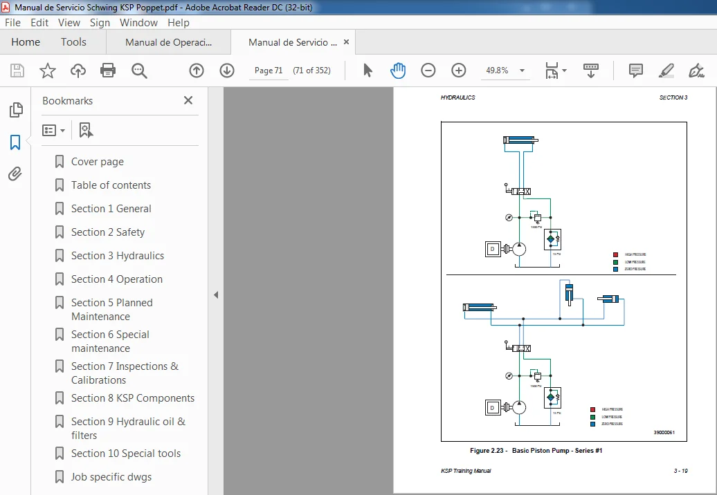
3.2 HYDRAULIC PUMPS ……………………………………………………………………………………3 – 8
TABLE OF CONTENTS
ii KSP Poppet Training Manual
3.3 VALVES ……………………………………………………………………………………………………… 3 – 12
3.3.1 Control Valves ……………………………………………………………………………….. 3 – 12
3.3.2 Relief Valves………………………………………………………………………………….. 3 – 12
3.3.3 The Basic Relief Valve ……………………………………………………………………. 3 – 14
3.4 HYDRAULIC SYMBOLS ……………………………………………………………………………….. 3 – 16
SECTION 4 OPERATION
4.1 BEFORE OPERATING SLUDGE PUMPS IN ANY MODE – POPPET …………………. 4 – 1
4.2 NOTES – POPPET ……………………………………………………………………………………….. 4 – 2
4.3 PREVENTIVE MAINTENANCE NOTES – POPPET ………………………………………….. 4 – 2
4.4 PRE-START-UP CHECKS ……………………………………………………………………………. 4 – 4
4.4.1 Sludge Pump …………………………………………………………………………………. 4 – 5
4.4.2 Screw Feeder ………………………………………………………………………………… 4 – 6
4.4.3 Hydraulic Power Pack …………………………………………………………………….. 4 – 7
4.4.4 Material Pipeline …………………………………………………………………………….. 4 – 8
4.4.5 Push Floor/Sliding Frames ………………………………………………………………. 4 – 9
4.4.6 Pipeline Lubrication ………………………………………………………………………… 4 – 10
4.5 START-UP PROCEDURE …………………………………………………………………………….. 4 – 11
4.5.1 General With Safety Precautions – Start-up………………………………………… 4 – 11
4.5.2 Starting and Stopping ……………………………………………………………………… 4 – 11
4.5.3 Emergency Stop …………………………………………………………………………….. 4 – 13
4.6 MATERIAL PUMP OPERATION ……………………………………………………………………. 4 – 14
4.6.1 The Control Panel…………………………………………………………………………… 4 – 14
4.6.2 SFMS and Transition Pressure Setpoint Selection………………………………. 4 – 15
4.6.3 Screw Feeder Modes ……………………………………………………………………… 4 – 16
4.6.4 Mode Selection ………………………………………………………………………………. 4 – 16
4.6.5 HMI Screens………………………………………………………………………………….. 4 – 18
4.7 LUBRICATION SYSTEM OPERATION …………………………………………………………… 4 – 25
4.7.1 Mode Selection ………………………………………………………………………………. 4 – 25
4.8 MATERIAL PUMP AND SCREW FEEDER ALARM CONDITIONS……………………… 4 – 26
4.9 LUBRICATION SYSTEM ALARM CONDITIONS ……………………………………………… 4 – 28
4.10 ADJUSTMENTS AND CHECKS DURING OPERATION …………………………………… 4 – 29
4.10.1 Safety Instructions – Adjustments & Checks……………………………………….. 4 – 29
4.10.2 Sludge Pump Output Adjustment – Electric ………………………………………… 4 – 29
4.10.3 Sludge Pump Output Adjustment – Manual Handwheel ……………………….. 4 – 30
4.10.4 Screw Feeder Output Adjustment – Electric………………………………………… 4 – 30
4.10.5 Screw Feeder Output Adjustment – Manual Handwheel……………………….. 4 – 31
4.10.6 Hydraulic System Checks – Rock Valve …………………………………………….. 4 – 32
4.10.7 Hydraulic System Checks/Adjust. – Poppet Valve ……………………………….. 4 – 32
4.10.8 Mechanical Checks ………………………………………………………………………… 4 – 32
4.10.9 Other Controls and Instruments ……………………………………………………….. 4 – 32
TABLE OF CONTENTS
KSP Poppet Training Manual iii
4.11 SHUTDOWN PROCEDURE …………………………………………………………………………..4 – 33
4.11.1 Shutdown For General Maintenance ………………………………………………….4 – 33
4.11.2 Short-Term Shutdown………………………………………………………………………4 – 35
4.11.3 Long Term Shutdown ………………………………………………………………………4 – 35
4.11.4 Long-Term Storage………………………………………………………………………….4 – 36
4.7.5 EMERGENCY STOP……………………………………………………………………….4 – 37
SECTION 5 PLANNED MAINTENANCE
5.1 SAFETY DURING MAINTENANCE …………………………………………………………………5 – 1
5.2 PERIODIC MAINTENANCE SCHEDULE …………………………………………………………5 – 3
5.2.1 General Maintenance ………………………………………………………………………5 – 7
5.2.2 Hydraulic power pack ………………………………………………………………………5 – 10
5.2.3 Push Floor Silo ……………………………………………………………………………….5 – 18
5.2.4 Screw Feeder …………………………………………………………………………………5 – 21
5.2.5 Material Pump…………………………………………………………………………………5 – 26
5.2.5 Pipeline Lubrication System ……………………………………………………………..5 – 33
5.3 LUBRICANT RECOMMENDATIONS ……………………………………………………………….5 – 35
5.3.1 Hydraulic oil recommendations (hydraulic power pack) ………………………..5 – 36
5.3.2 Gear-lubricant recommendations ………………………………………………………5 – 37
5.3.3 Grease recommendations ………………………………………………………………..5 – 37
5.4 TROUBLESHOOTING …………………………………………………………………………………..5 – 38
5.4.1 Hydraulic Power Pack………………………………………………………………………5 – 38
5.4.2 Push Floor Silo ……………………………………………………………………………….5 – 40
5.4.3 Screw Feeder …………………………………………………………………………………5 – 41
5.5 BOLT TORQUE TABLES ……………………………………………………………………………….5 – 45
5.5.1 Metric: normal threads……………………………………………………………………..5 – 45
5.5.2 Metric: fine threads ………………………………………………………………………….5 – 46
SECTION 6 SPECIAL MAINTENANCE
SERVICE AND REPAIR INSTRUCTIONS
6.1 SAFETY DURING MAINTENANCE (From you O&M Manual) ……………………………..6 – 2
6.2 MAINTAINING HYDRAULIC SYSTEM PRESSURES…………………………………………6 – 3
6.3 SCREW FEEDER………………………………………………………………………………………….6 – 4
6.3.1 Auger replacement ………………………………………………………………………….6 – 4
6.4 MATERIAL PUMP………………………………………………………………………………………….6 – 6
6.4.1 Replacing piston heads ……………………………………………………………………6 – 6
6.4.2 Replacing poppet valves…………………………………………………………………..6 – 14
TABLE OF CONTENTS
iv KSP Poppet Training Manual
SECTION 7 INSPECTIONS & CALIBRATIONS
7.1 SLUDGE FLOW MEASURING SYSTEM (SFMS®) SET-UP ………………………………4
7.1.1 Overview of the SFMS® and the Schwing Pump …………………………………4
7.1.2 SFMS® Calculations ……………………………………………………………………….7
7.1.3 Throttle Valve Adjustment ………………………………………………………………..8
7.1.4 Throttle Check Valve Adjustment ………………………………………………………9
7.1.5 Proximity Switch Set-up……………………………………………………………………10
7.1.6 SFMS® Functional Test #1 -KSP ………………………………………………………12
7.1.7 SFMS® Functional Test #2 – EKSP……………………………………………………12
7.1.8 SFMS® Calibration………………………………………………………………………….13
7.1.9 Testing and Calibration of SFMS® …………………………………………………….14
SECTION 8 KSP COMPONENTS
8.1 SCREW FEEDER COMPONENTS ………………………………………………………………… 8 – 1
8.1.1 Screw Feeder Gear Box ………………………………………………………………….. 8 – 2
8.2 SCREW FEEDER SHAFT TIMING …………………………………………………………………. 8 – 8
8.3 SLUDGE PUMP COMPONENTS …………………………………………………………………… 8 – 27
SECTION 9 HYDRAULIC OIL & FILTERS
9.1 RESERVOIRS …………………………………………………………………………………………….. 9 – 1
9.2 HYDRAULIC OILS AND LUBRICANTS …………………………………………………………… 9 – 1
9.3 FLUID CONTAMINATION AND CONTROL …………………………………………………….. 9 – 3
9.3.1 Handling, Storing, and Dispensing of Lubricating Fluids ………………………. 9 – 4
9.4 FILTERS ……………………………………………………………………………………………………..9 – 6
9.5 TECHNICAL INFORMATION – FILTRATION RATINGS ……………………………………. 9 – 6
9.5.1 Nominal Filtration Ratings ……………………………………………………………….. 9 – 6
9.5.2 Absolute Filtration Ratings……………………………………………………………….. 9 – 6
9.5.3 Beta Filtration Ratio (bn)………………………………………………………………….. 9 – 6
9.5.4 Filter Facts…………………………………………………………………………………….. 9 – 7
9.5.5 Technical Information – Beta Ratings ………………………………………………… 9 – 8
9.6 SCHWING BIOSET FILTERS ……………………………………………………………………….. 9 – 9
9.6.1 KSP Return Filter……………………………………………………………………………. 9 – 9
9.6.2 Conditioning Loop Filter…………………………………………………………………… 9 – 11
9.7 HYDRAULIC PUMPS …………………………………………………………………………………… 9 – 12
9.8 REXROTH VT 2000 AMPLIFIER CARD ………………………………………………………….. 9 – 18
9.8.1 Functional Description of the Rexroth VT2000 Amplifier Card ………………. 9 – 18
9.9 PRESSURE SWITCHES ………………………………………………………………………………. 9 – 21
9.9.1 How To Set Pressure Switches ………………………………………………………… 9 – 21
TABLE OF CONTENTS
KSP Poppet Training Manual v
9.9.2 Switch Adjustments …………………………………………………………………………9 – 26
9.9.3 Temperature Switch Adjustment………………………………………………………..9 – 29
9.9.4 Combination Level and Temperature Switch……………………………………….9 – 31
9.9.5 Dirty Oil Filter Switch ……………………………………………………………………….9 – 32
9.10 TYPES OF HEAT EXCHANGERS ………………………………………………………………….9 – 35
9.11 HYDRAULIC SCHEMATIC SERIES – KSP POPPET …………………………………………9 – 38
9.11.1 KSP Poppet Valve – Series #1…………………………………………………………..9 – 38
9.11.2 KSP Poppet Valve – Series #2…………………………………………………………..9 – 40
9.11.3 KSP Poppet Valve – Series #3…………………………………………………………..9 – 42
9.11.4 KSP Poppet Valve – Series #4…………………………………………………………..9 – 44
9.11.5 KSP Poppet Valve – Series #5…………………………………………………………..9 – 46
9.11.6 KSP Poppet Valve – Series #6…………………………………………………………..9 – 48
9.11.7 KSP Poppet Valve – Series #7…………………………………………………………..9 – 50
9.12 UNIT IS IN REVERSE …………………………………………………………………………………..9 – 52
9.12.1 KSP Poppet Valve – Series #8…………………………………………………………..9 – 52
9.13 EXCESS ROCKING OIL CONDITION ……………………………………………………………..9 – 54
9.13.1 KSP Poppet Valve – Series #9…………………………………………………………..9 – 54
9.14 ADDING ROCKING OIL CONDITION ……………………………………………………………..9 – 56
9.14.1 KSP Poppet Valve – Series #10…………………………………………………………9 – 56
SECTION 10 SPECIAL TOOLS
10.1 HYDRAULIC TROUBLE SHOOTING KITS ………………………………………………………10 – 1
10.2 FLOW METERS AND ACCESSORIES ……………………………………………………………10 – 2
10.3 MATERIAL CYLINDER ALIGNMENT TOOLS …………………………………………………..10 – 3
10.4 PISTON INSTALLATION TOOLS ……………………………………………………………………10 – 4
10.5 ROD GLAND PACKING INSTALLATION TOOLS ……………………………………………..10 – 5
10.6 RAM TOOLS ………………………………………………………………………………………………..10 – 6
10.7 TORQUE SPECIFICATIONS FOR METERIC BOLTS AND SCREWS
USED ON SCHWING EQUIPMENT ………………………………………………………………..10 – 7
10.6.1 Dacromet 500 Screws and Nuts DIN 912, 931, 933, 934
(Hexagon, Machine Screws, and Hexagon Nuts)…………………………………10 – 8
10.6.2 Dacromet 500 Screws and Nuts DIN 6914, 6915 (HV Screws)………………10 – 10
10.6.3 Black Screws and Nuts DIN 912, 931, 933, 934
(Hexagon, Machine Screws, and Hexagon Nuts)…………………………………10 – 11
10.8 CONVERSION CHART …………………………………………………………………………………10 – 13
10.9 FLUID POWER FORMULAS ………………………………………………………………………….10 – 16
10.10 DRILL SIZES FOR METRIC TAPS ………………………………………………………………….10 – 18
Description:
2011 Schwing bioset KSP Poppet Manual
1.1 PURPOSE OF THIS MANUAL This manual is designed to assist you in the Installation, Operation, and Maintenance of your custom designed Schwing Bioset Sludge Pump system.
It describes storage, installation, start-up, normal operation, shut-down, periodic maintenance, and trouble shooting procedures. It also contains detailed layout drawings, hydraulic schematics, electrical schematics, and parts book drawings. The installers, operators, maintenance personnel, and everyone involved with these systems should study this manual carefully.
We hope that it can help in your ongoing training and maintenance program. 1.2 DESCRIPTION OF EQUIPMENT 1.2.1 General Description A specially sized and configured Sludge Pump System supplied by Schwing Bioset consists of one or more sets of the following equipment:
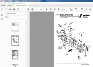
• Hydraulically Driven Piston Pump • Screw Feeder/Agitator Hopper. • Hydraulic Power Pack, to power the pump and screw feeder/agitator hopper. • Special Feed hoppers or Hopper Adapters. • Material Pipeline, steel with pressure tight seals. (OPTIONAL) • Control Systems • Sliding Frames • Push Floors • Pipeline Lubrication System They are described further in the following paragraphs and detailed specifications for the installed equipment in your O&M manual.
The system is custom designed to pump dewatered sludges or slurries through pressurized steel pipelines to dryers, incinerators, or distribution systems.
The electric motor of the Hydraulic Power Pack drives hydraulic pumps that drive the cylinders of the Sludge Pump and the hydraulic motors of the Screw Feeder or Hopper Agitator.
Custom controls, monitors and sensors are installed to specifications to provide automatic, dependable operation.
Please Note:
- This is the SAME exact manual used by your dealers to fix your vehicle.
- The same can be yours in the next 2-3 mins as you will be directed to the download page immediately after paying for the manual.
- Any queries / doubts regarding your purchase, please feel free to contact [email protected]