2017 Harley Davidson Softail Models Service Manual – PDF DOWNLOAD
Original price was: $89.95.$27.95Current price is: $27.95.
2017 Harley Davidson Softail Models Service Manual – PDF DOWNLOAD
Description
2017 Harley Davidson Softail Models Service Manual – PDF DOWNLOAD
IMAGES PREVIEW OF THE MANUAL:


DESCRIPTION:
2017 Harley Davidson Softail Models Service Manual – PDF DOWNLOAD
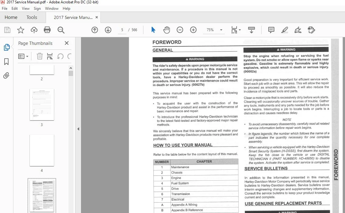
GENERAL:
- To acquaint the user with the construction of the Harley-Davidson product and assist in the performance of basic maintenance and repair.
- To introduce the professional Harley-Davidson technician to the latest field-tested and factory-approved major repair methods.
HOW TO USE YOUR SERVICE MANUAL
Refer to the table below for the content layout of this manual.
NO. CHAPTER
1 Maintenance
2 Chassis
3 Engine
4 Fuel System
5 Drive
6 Transmission
7 Electrical
A Appendix A Connector Repair
B Appendix B Wiring
- Use the TABLE OF CONTENTS (which follows this FOREWORD) and the INDEX (at the back of this manual) to quickly locate subjects. Sections and topics in this manual are sequentially numbered for easy navigation.
- For example, a cross-reference shown as 2.1 SPECIFICATIONS refers to chapter 2 CHASSIS, heading 2.1 SPECIFICATIONS.
- For quick and easy reference, all pages contain a section number followed by a page number. For example, page 3-5 refers to page 5 in section 3.
- A number of acronyms and abbreviations are used in this document. See the D.1 GLOSSARY for a list of acronyms, abbreviations and definitions.
TABLE OF CONTENTS:
2017 Harley Davidson Softail Models Service Manual – PDF DOWNLOAD
MAINTENANCE
1 1 FASTENER TORQUE VALUES
Fastener Torque Values in this Chapter 1-1
1 2 GENERAL
Servicing а New Motorcycle 1-3
Safe Operating Maintenance 1-3
Disposal and Recycling 1-3
Shop Practices 1-3
Repair Notes 1-3
Safety 1-3
Removing Parts 1-3
Cleaning 1-3
Cleaning Fastener Threads 1-4
DisassemЫy and AssemЫy 1-4
Checking Torques оп Fasteners 1-4
Magnetic Parts Trays 1-4
Repair and Replacement Procedures 1-4
Hardware and Threaded Parts 1-4
Threadlocking Agents 1-4
Wiring, Hoses and Lines 1-4
lnstruments and Gauges 1-4
Bearings 1-4
Bushings 1-4
Gaskets 1-4
Lip-Type Seals 1-5
O-Rings 1-5
Gears 1-5
Shafts 1-5
Part Replacement 1-5
Cleaning 1-5
Protecting Rubber Parts 1-5
Cleaning Process 1-5
Rust or Corrosion Removal 1-5
Bearings 1-5
Tool Safety 1-5
Air Tools 1-5
Wrenches 1-6
Pliers/Cutters/Pry Bars 1-6
Hammers 1-6
Punches/Chisels 1-6
Screwdrivers 1-6
Ratchets and Handles 1-6
Sockets 1-6
Storage Units 1-6
1 3 FUEL AND OIL
Fuel 1-7
Gasoline Blends 1-7
Engine Lubrication: Twin Cam 103 1-7
Engine Lubrication: Twin Cam 110 1 -8
Low Temperature Lubrication 1-8
1 4 MAINTENANCE SCHEDULE
General 1-9
1 5 ENGINE OIL AND FILTER
Checking and Adding Oil 1-14
Changing Oil and Oil Filter 1-14
1 6 AIR CLEANER AND EXHAUST SYSTEM
Air Cleaner: AII except FLSS, FLSTFBS 1-16
Removal 1-16
lnstallation 1-16
Air Cleaner: FLSTFBS 1-16
Rain Sock 1-16
Removal 1-17
lnstallation 1-17
Air Cleaner: FLSS 1-17
Removal 1-17
lnstallation 1-17
Cleaning Filter Element 1-17
Check Exhaust System Leakage 1-18
Exhaust System Leakage 1-18
1 7 TIRES AND WHEELS
General 1-19
Tires 1-19
Tire Replacement 1-20
1 nspection 1-20
When То Replace Tires 1 -20
Wheel Bearings 1-20
Wheel Spokes 1-20
ldentify Wheel Spoke Groups 1-20
Adjust Wheel Spokes 1-21
1 8 PRIMARY CHAINCASE LUBRICANT
General 1-22
Change Primary Chaincase Lubricant 1-22
1 9 TRANSMISSION LUBRICANT
Check Transmission Lubricant 1-24
Change Transmission Lubricant 1-24
1 10 CLUTCH: MECHANICAL CLUTCH
Adjustment 1-26
1 11 HYDRAULIC CLUTCH FLUID:
HYDRAULIC CLUTCH
General 1-28
Check Clutch Fluid 1-28
Replace Clutch Fluid 1-28
1 12 DRIVE BELT AND SPROCKETS
General 1-30
Cleaning 1-30
1 nspection 1-30
Sprockets 1-30
Drive Belt 1-30
Check Drive Belt Deflection 1-31
Adjusting Drive Belt Deflection 1-32
1 13 CABLE AND CHASSIS LUBRICATION
General 1-34
СаЫеs and Hand Levers 1-34
Jiffy Stand 1-34
STEERING HEAD BEARINGS 1-34
1 14 BRAKES
Fluid lnspection 1-35
lnspect Brake Lines 1-36
1 15 BRAKE PADS AND DISCS
lnspection 1-37
Brake Pads 1-37
Brake Disc 1-37
TABLE OF CONTENTS
Brake Pad Replacement 1-37
Rear Brake Caliper 1-37
Front Brake Caliper 1-39
1 16 SPARK PLUGS
Remove 1-41
lnspect 1-41
Clean 1-41
lnstallation 1 -41
1 17 STEERING HEAD BEARINGS
Adjustment: FLSTC, FLSTF, FLSTFB, FLSTFBS, FLSTN, FLS,
FLSS 1-43
Bearing Adjustment (Fall-Away) 1-43
Adjustment: FXSB 1-44
Bearing Adjustment (Fall-away) 1-44
Lubrication 1-45
1 18 BATTERY MAINTENANCE
General 1 -46
Cleaning and lnspection 1-47
Voltage Test 1-47
Battery Tender Connector 1-47
Charging Battery 1-48
Safety Precautions 1-48
Using а Battery Charger 1-48
Battery Disconnection and Removal 1-49
Storage 1-49
Battery lnstallation and Connection 1-49
1 19 HEADLAMP ALIGNMENT
Headlamp Alignment 1-52
Headlamp Adjustment 1-52
1 20 SUSPENSION ADJUSTMENTS
Shock Absorbers 1-53
Calculate Number of Preload Turns 1-53
Adjustment 1-53
1 21 STORAGE
General 1-54
Placing in Storage 1-54
Removal From Storage 1-54
1 22 TROUBLESHOOTING
General 1-55
Engine 1-55
Starter Motor Does Not Орегаtе ог Does Not Turn Engine
Over 1-55
Engine Turns Over But Does Not Start 1 -55
Starts Нагd 1-55
Starts But Runs lrregularly ог Misses 1-55
А Spark Plug Fouls Repeatedly 1-55
Pre-lgnition ог Detonation (Knocks ог Pings ) 1-56
Overheating 1-56
Valve Train Noise 1-56
Excessive Vibration 1-56
Check Engine Light llluminates During Operation 1-56
Lubrication System 1-56
Oil Does Not Return То Oil Tank 1-56
Engine Uses Тоо Much Oil Ог Smokes Excessively 1-56
Engine Leaks Oil From Cases, Pushrods, Hoses,
Etc 1-56
TABLE OF CONTENTS IV
Low Oil Pressure 1-56
High Oil Pressure 1-57
Electrical System 1-57
Alternator Does Not Charge 1-57
Alternator Charge Rate Is Below Normal 1-57
Speedometer Operates Erratically 1-57
Transmission 1-57
Shifts Нагd 1-57
Jumps Out Of Gear 1-57
Clutch Slips: Mechanical 1-57
Clutch Slips: Hydraulic 1-57
Clutch Drags Ог Does Not Release 1-57
Clutch Chatters 1-57
Handling 1-57
lrregularities 1-57
BRAKES 1-57
Вгаkе Does Not Hold Normally 1-57
CHASSIS
2 1 FASTENER TORQUE VALUES
Fastener Torque Values in this Chapter 2-1
2 2 SPECI FICATIONS
Specifications 2-5
Chassis Specifications 2-5
Тiге Specifications 2-6
2 3 VEHICLE IDENTI FICATION NUMBER
(V I N )
Vehicle ldentification Number 2-8
2 4 FRONT WHEEL
Removal 2-1 О
DisassemЬly 2-10
Disc Wheel 2-10
Laced Wheel 2-10
Cleaning and lnspection 2-12
AssemЫy 2-12
Disc Wheel 2-12
Laced Wheel 2-13
lnstallation 2-13
2 5 REAR WHEEL
Removal 2-14
DisassemЫy 2-14
Cleaning and lnspection 2-15
AssemЫy 2-15
lnstallation 2-16
2 6 WHEEL LACING
Wheel Lacing: Angle Flange Hub 2-17
2 7 CHECКING AND TRUING WHEELS
General 2-19
Checking Wheel Runout 2-19
Checking Radial Runout 2-19
Checking Lateral Runout 2-19
Laced Wheel Rim Offset 2-20
True Laced Wheels 2-21
Adjust Radial Runout 2-21
Adjust Lateral Runout 2-22
TABLE OF CONTENTS
2 8 SEALED WHEEL BEARINGS
lnspect 2-23
Removal 2-23
lnstallation 2-24
2 9 TIRES
General 2-26
Removal 2-26
Clean, lnspect and Repair 2-26
lnstall 2-27
Tube-Type Тires 2-27
Tubeless Tires: Cast Wheels 2-27
Tubeless Tires: Laced Wheels 2-28
Check Tire Runout 2 -29
Lateral Runout 2-29
Radial Runout 2-29
Balance Wheel 2-29
Static vs Dynamic 2-29
Weights 2-29
2 10 VEHICLE ALIGNMENT
Axle Alignment 2-31
Checking Axle Alignment 2-31
Adjusting Axle Alignment 2 -31
2 11 FRONT BRAKE MASTER CYLINDER
General 2-33
Removal and DisassemЫy 2-33
Cleaning and lnspection 2-34
AssemЫy and lnstallation 2-34
2 12 FRONT BRAKE CALIPER
Removal 2-36
DisassemЫy 2-36
Cleaning, lnspection and Repair 2-37
AssemЫy 2-38
lnstallation 2-38
2 13 REAR BRAKE MASTER CYLINDER
General 2-39
Rear Вгаkе Pedal 2-39
Pedal Height 2-39
Pedal Replacement 2-39
Pedal Pad 2-39
Removal 2-39
DisassemЫy 2-39
Cleaning and lnspection 2-40
AssemЫy 2-41
lnstallation 2-41
2 14 REAR BRAKE CALIPER
Removal 2-45
DisassemЫy 2-45
Cleaning, lnspection and Repair 2-47
AssemЫy 2-47
Rear Brake Line Routing 2-48
lnstallation 2-48
2 15 BRAKE LINES
Front Master Cylinder to Front HCU 2-50
Removal 2-50
1 nstallation 2-50
HCU to Front Brake Caliper 2-50
Removal 2-50
lnstallation 2-51
Rear Master Cylinder to Rear HCU 2-51
Removal 2-51
lnstallation 2-52
Rear HCU to Rear Brake Caliper 2-53
Removal 2-53
lnstallation 2-54
2 16 ABS: ELECTRONIC CONTROL UNIT
(ECU)
Removal: AII But FXSB 2-55
lnstallation: AII But FXSB 2-55
Removal: FXSB 2-56
lnstallation: FXSB 2-56
2 17 ABS: HYDRAULIC CONTROL UNIT
(HCU)
Front Hydraulic Control Unit (HCU) 2-57
Removal 2-57
lnstallation 2-57
Rеаг Hydraulic Control Unit (HCU) 2-58
Removal 2-58
lnstallation 2-58
2 18 BLEEDING BRAKES
General 2-60
Procedure 2-60
2 19 FRONT FORK
General 2-62
Check For Oil Leak 2-62
Fork Oil Seals 2-62
Check Oil Leak 2-62
Replacing Fork Oil 2-62
Removal 2-63
DisassemЫy 2-63
Clean and lnspect 2-66
AssemЫy 2-66
lnstallation 2-66
2 20 STEERING HEAD
Removal 2-68
FLSTC, FLSTF, FLSTFB, FLSTFBS, FLSTN, FLS, FLSS
Models 2-68
FXSB Models 2-68
lnspection 2-68
AII Models 2-68
DisassemЫy 2-69
Removing Lower Bearings From Fork Stem 2-69
Steering Head Bearing Race Removal 2-69
AssemЬly 2-69
lnstallation 2-70
FLSTC, FLSTF, FLSTFB, FLSTFBS, FLSTN, FLS, FLSS
Models 2-70
FXSB Model 2-70
2 21 BELT GUARD AND DEBRIS
DE FLECTOR
Removal 2-71
Belt Guard 2-71
Debris Deflector 2-71
lnstallation 2-71
Belt Guard 2-71
Debris Deflector 2-71
TABLE OF CONTENTS V
TABLE OF CONTENTS
2 22 REAR SHOCK ABSORBERS
General 2-72
Removal 2-72
lnstallation 2-72
Shock Disposal 2-73
2 23 REAR FORK
Removal 2-74
Cleaning and lnspection 2-75
Pivot Bearing Replacement 2-75
lnstallation 2-76
2 24 CLUTCH CONTROL: MECHANICAL
CLUTCH
Removal 2-77
lnstallation 2-77
2 25 CLUTCH MASTER CYLINDER AND
RESERVOIR: HYDRAULIC CLUTCH
Remove 2-79
DisassemЫe 2-79
Cleaning and lnspection 2-79
AssemЫe 2-80
lnstall 2-80
2 26 CLUTCH HAND LEVER: HYDRAULIC
CLUTCH
Remove 2-81
lnstall 2-81
2 27 CLUTCH FLUID LINE: HYDRAULIC
CLUTCH
Replacement 2-82
Removal 2-82
1 nstallation 2-82
2 28 BLEEDING CLUTCH FLUID LINE:
HYDRAULIC CLUTCH
Drain and Fill 2-84
Drain 2-84
Fill 2-84
Bleed Fluid Line and Secondary Clutch Actuator 2-84
2 29 LE FT HANDLEBAR GRIP
Removal and lnstallation 2-86
Removal 2-86
1 nstallation 2-86
2 30 HANDLEBAR: FLSTC, FLSTN, FLS,
FLSS
Removal 2-87
lnstallation 2-87
2 31 HANDLEBAR: FLST F, FLST FB,
FLST FBS
Removal 2-89
lnstallation 2-89
2 32 HANDLEBAR: FXSB
Removal 2-91
lnstallation 2-91
TABLE OF CONTENTS VI
2 33 FRONT FENDER
Removal 2-93
lnstallation 2-93
2 34 REAR FENDER: FLSTC
Removal 2-94
lnstallation 2-94
2 35 REAR FENDER: FLST F, FLST FB,
FLST FBS
Removal 2-96
lnstallation 2-96
2 36 REAR FENDER: FLS, FLSS
Removal 2-97
lnstallation 2-97
License Plate Bracket AssemЫy and lnstallation: FLS,
FLSS (all but Domestic and California models) 2-97
License Plate Bracket AssemЫy and lnstallation: FLS,
FLSS (Domestic and California models) 2-98
Fender lnstallation 2-98
2 37 REAR FENDER: FXSB
Removal 2-100
lnstallation 2-100
2 38 REAR FENDER: FLSTN
Removal 2-102
DisassemЬly 2-102
AssemЫy 2-103
1 nstallation 2-104
2 39 REAR FENDER WIRE CONDUIT
lnstallation 2-105
2 40 FOOTBOARDS AND FOOTRESTS
Rider Footboards 2-106
Removal 2-106
lnstallation 2-106
Rider Footrests 2-106
Removal 2-106
lnstallation 2-106
Passenger Footrests 2-106
Removal 2-106
lnstallation 2-107
2 41 JI F FY STAND
Cleaning 2-108
Sensor: HDI Models 2-108
Removal 2-108
lnstallation 2-108
2 42 FORK LOCK
Removal 2-110
lnstallation 2-110
2 43 SEAT AND STRAP RETENTION NUT
Replacement 2-111
2 44 SEAT: FLS, FLSS, FXSB
Replacement 2-112
Removal 2-112
TABLE OF CONTENTS
lnstallation 2-112
2 45 SEAT: FLSTN, FLSTF, FLSTFB,
FLSTFBS, FLSTC
Removal and lnstallation 2-113
2 46 LUGGAGE RACK: FLSTN
Removal and lnstallation 2-114
2 47 SADDLEBAGS: FLSTC
Removal 2-115
lnstallation 2-115
2 48 WINDSHIELD: FLSTC
Removal 2-116
lnstallation 2-116
2 49 SAREE GUARD: INDIA MODELS
Uррег Sагее Guards: AII Models Except FXSB 2-117
Removal 2-117
lnstallation 2-117
Uррег Sагее Guards: FXSB 2-117
Removal 2-117
lnstallation 2-117
Lower Sагее Guard 2-117
Removal 2-117
lnstallation 2-117
2 50 FRONT LICENSE PLATE BRACKET
Removal and lnstallation 2-118
2 51 MEDALLIONS, BADGES AND TANK
EMBLEMS
Removal 2-119
lnstallation 2-119
ENGINE
3 1 FASTENER TORQUE VALUES
Fastener Torque Values in this Chapter 3-1
3 2 SPECIFICATIONS
Specifications 3-4
3 3 SERVICE WEAR LIMITS
General 3-6
3 4 ENGINE OIL FLOW
Oil Feed 3-8
Тор End 3-8
Bottom End 3-10
Chain Guide Bracket 3-11
Oil Return 3-12
3 5 OIL PUMP OPERATION
General 3-13
Operation 3-13
3 6 BREATHER OPERATION
General 3-14
3 7 OIL PRESSURE
Oil Pressure lndicator Lamp 3-15
Oil Pressure Check 3-15
3 8 TROUBLESHOOTING
Diagnosing Valve Train Noise 3 -16
Compression Test 3-16
Cylinder Leakdown Test 3-17
Diagnosing Smoking Engine ог High Oil Consumption 3-17
Check Веfоге Cylinder Head Removal: 3-17
Check After Cylinder Head Removal: 3-17
3 9 HOW ТО USE THIS SECTION
Тор End Repair 3-18
Bottom End Repair 3-18
Typical Symptoms 3-18
3 1 О ТОР END SERVICE
Engine in Chassis 3-19
Engine Removed from Chassis 3-19
3 11 САМ COMPARTMENT SERVICE
Replace Camshaft 3-20
Engine Removed from Chassis 3-20
3 12 STRIPPING MOTORCYCLE FOR
SERVICE
Procedure 3-22
Cam Compartment Service Only 3-22
Complete Тор End Service 3-22
3 13 ASSEMBLING MOTORCYCLE AFTER
SERVICE
Procedure 3-23
After Complete Тор End Service 3-23
After Cam Compartment Service Only 3-23
3 14 REMOVING ENGINE FROM CHASSIS
Procedure 3-24
3 15 INSTALLING ENGINE IN CHASSIS
Procedure 3-25
3 16 ТОР END OVERHAUL: DISASSEMBLY
General 3-27
Rocker Covers 3-27
Rocker Агm Support Plate 3-27
Pushrods, Lifters and Covers 3-29
CYLINDER HEAD 3-29
Cylinder 3-30
Piston 3-31
3 17 BREATHER ASSEMBLY
DisassemЫy 3-33
Cleaning and lnspection 3-33
AssemЫy 3-33
3 18 ROCKER ARM SUPPORT PLATE
DisassemЫy 3-34
Cleaning, lnspection and Repair 3-34
lnspection 3-34
Rocker Shaft Fit 3-34
Rocker Агm Shaft to Bushing 3-35
Replace Rocker Агm Bushings 3-35
AssemЫy 3-36
TABLE OF CONTENTS VII
TABLE OF CONTENTS
3 19 PUSHRODS, LI FTERS AND COVERS
Di sassemЫy 3-37
Clean and lnspect 3-37
lnspect Lifters 3-37
AssemЫe Pushrod Cover 3-37
3 20 CYLINDER HEAD: ТWIN САМ 103
lnspect Valve Sealing 3-39
DisassemЫy 3-39
Cleaning 3-40
1 nspection 3-40
Cylinder Head 3-40
Valve Guides 3-41
Valves 3 -41
Valve Springs 3-41
Tapered Keepers 3-41
Valve Seats 3-41
Valve Guide Replacement 3-41
Removal 3-41
lnstallation 3-42
Valve and Seat Refacing 3-44
AssemЫy 3-46
3 21 CYLINDER HEAD: ТWIN САМ 110
Cylinder Head Repair 3-48
3 22 CYLINDER : ТWIN САМ 103
Cleaning 3-49
1 nspection 3-49
Deglazing Cylinder 3-50
Boring and Honing Cylinder 3-51
3 23 CYLINDER: ТWIN САМ 110
lnspection 3-52
Cylinder Воге Finished Size 3-52
3 24 PISTON: ТWIN САМ 103
DisassemЫy 3-53
Piston Rings 3-53
Cleaning 3-53
1 nspection 3-53
AssemЬly 3-55
Checking Piston Ring Gap 3-55
lnstalling Piston Rings 3-55
3 25 PISTON: TWIN САМ 110
Checking Piston Clearance 3-57
3 26 ТОР END OVERHAUL: ASSEMBLY
General 3-58
Piston 3-58
Cylinder 3-59
CYLINDER HEAD 3-60
Pushrods, Lifters and Covers 3-63
Rocker Arm Support Plate 3-64
Breather and Rocker Cover 3-65
3 27 САМ COMPARTMENT AND
COMPONENTS
Cam Support Plate and Cover Removal 3-67
Ргераге Engine 3-67
Cam Chain and Sprockets Removal 3-67
TABLE OF CONTENTS V I II
Cam Support Plate Removal 3-68
Cam Support Plate Cleaning and lnspection 3-69
Oil Pressure Relief Valve 3-69
Cam Support Plate 3-69
Camshafts 3-69
Removal 3-69
lnstallation 3-70
Oil Pressure Relief Valve 3-71
Removal 3 -71
lnspection 3-72
lnstallation 3-72
Cam Needle Bearings 3-72
Removal 3-72
1 nstallation 3-73
Cam Support Plate and Cover lnstallation 3-74
3 28 OIL PUMP
Removal 3-79
Cleaning and lnspection 3-79
1 nstal lation 3-80
3 29 CRANKCASE DISASSEMBLY AND
REPAIR: ТWIN САМ 103
Crankcase DisassemЫy 3-81
Counterbalancer AssemЫy 3-81
Cleaning and lnspection 3-83
Right Crankcase Half 3-83
Chain Guide Screen 3-83
Main Bearing Removal 3-83
Main Bearing lnstallation 3-84
Piston Jets Removal 3-85
Piston Jets lnstallation 3-85
Left Crankcase Half 3-85
Main Bearing Removal 3-86
Main Bearing lnstallation 3-87
Sprocket Shaft Bearing lnner Race 3-87
Removal 3-87
lnstallation 3-88
Cylinder Studs 3-89
Remove 3-89
1 nstal1 3 -90
Pipe Plugs and Oil Fittings 3-90
Removal/lnstallation 3-90
3 30 CRANKCASE DISASSEMBLY AND
REPAIR: ТWIN САМ 11 О
General 3-91
3 31 F LYWHEEL AND CONNECTING RODS
Symptoms 3-92
Overview 3-92
No Oil Pressure 3-92
Vibration 3-92
lnspection 3-92
Measuring Crankshaft Runout 3-92
Crankshaft lnstalled 3-92
Crankshaft Removed 3-93
3 32 COUNTERBALANCER ASSEMBLY
REPAIR
Cleaning, lnspection and Repair 3-95
General 3-95
Balance Shaft Removal 3-95
TABLE OF CONTENTS
Bearing Removal 3-96
Balance Shaft lnstallation 3-96
Balance Shaft Support Bearings Removal 3-97
Balance Shaft Support Bearings lnstallation 3-97
Front and Rear Balance Sprockets 3-98
Hydraulic Tensioners 3-98
Chain Tensioner Guides 3-98
Balance Shaft Support 3-98
Balance Chain 3-98
3 33 CRANKCASE ASSEMBLY
Counterbalancer AssemЫy lnstallation 3-1 00
CRANKCASE ASSEMBLY 3-1 03
3 34 OIL TANK: ALL BUT FXSB
Removal and DisassemЫy 3-106
Oil Tank 3-106
Oil Line Fittings/Retainers 3-107
lnstallation 3-108
3 35 OIL TANK: FXSB
Removal and DisassemЫy 3-11 О
Oil Tank 3-110
Oil Line Fittings/Retainers 3 -112
lnstallation 3-113
FUEL SYSTE M
4 1 FASTENER TORQUE VALUES
Fastener Torque Values in this Chapter 4-1
4 2 SPECI FICATIONS: FUEL SYSTEM
Specifications 4-3
4 3 FUEL PRESSURE TEST
General 4-4
Testing 4-4
4 4 INTAKE LEAK TEST
General 4-6
Leak Tester 4-6
Parts List 4-6
AssemЫe Tester 4-6
Adjust Tester 4-6
Procedure 4-6
4 5 AIR CLEANER
Air Cleaner: AII But FLSTFBS, FLSS 4-8
Removal 4-8
lnstallation 4-8
Replace lnsert: With Screw Access 4-8
Replace lnsert: Without Screw Access 4-8
Snorkel 4-8
Air Cleaner: FLSTFBS 4-9
Removal 4-9
lnstallation 4-9
Air Cleaner: FLSS 4-1 0
Removal 4-1 0
1 nstallation 4-1 О
4 6 FUEL SUPP LY LINE
Purge Fuel Supply Line 4-1 1
Disconnect Fuel Supply Line 4-1 1
4 7 CONSOLE: FXSB
Removal 4-12
lnstallation 4-12
4 8 FUEL TANK
General 4-1 3
Removal 4-13
Cleaning and lnspection 4-14
lnstallation 4-14
Fuel Supply Check Valve/Тube 4-15
Removal 4-1 5
lnstallation 4-15
4 9 ТWIST GRIP SENSOR (TGS)
Remove 4-17
lnstall 4-17
4 1 О THROTTLE CONTROL ACTUATOR
( ТСА)
General 4-19
4 11 INDUCTION MODULE
Removal 4-20
lnstallation 4-21
4 12 TEMPERATURE MANI FOLD ABSOLUTE
PRESSURE SENSOR ( ТМАР)
Removal 4-22
lnstallation 4-22
4 1 З HEATED OXYGEN SENSORS ( НО2)
General 4-23
Removal 4-23
Front НО2 Sensor 4-23
Rear НО2 Sensor 4-23
lnstallation 4-23
Front НО2 Sensor 4-23
Rear НО2 Sensor 4-23
4 14 FUEL INJECTORS
General 4-25
Removal 4-25
lnstallation 4-25
4 15 ENGINE TEMPERATURE SENSOR ( ЕТ)
General 4-27
Removal 4-27
lnstallation 4-27
4 16 FUEL PUMP AND FUEL GAUGE
SENDING UNIT
General 4-28
Removal 4-28
Vapor Valve 4-29
DisassemЫy And AssemЫy 4-30
Fuel Filter 4-30
Regulator 4-30
lnlet sock 4-31
Fuel Pump 4-31
lnstallation 4-32
4 17 EXHAUST SYSTEM
Mufflers: FLSTC, FXSB (AII But ENG, HD I, IND and JPN
Markets) 4-33
TABLE OF CONTENTS IX
TABLE OF CONTENTS
Removal 4-33
AssemЫy 4-33
System: FLSTC, FXSB {AI I But ENG, HDI , IND and JPN
Markets) 4 -33
Removal 4-33
lnstallation 4-33
Mufflers: FLSTC and FXSB (ENG, HDI, IND and JPN
Ма rkets) 4-34
Removal 4-34
AssemЫy 4-34
System: FLSTC and FXSB (ENG, HDI, IND and JPN
Markets ) 4-35
Removal 4 -35
lnstallation 4-35
Mufflers: FLSTN, FLSTF, FLSTFB, FLSTFBS, FLS,
FLSS 4 -36
Removal 4 -36
AssemЫy 4-36
System: FLSTN, FLSTF, FLSTFB, FLSTFBS, FLS,
FLSS 4 -37
Removal 4-37
lnstallation 4-37
4 18 EVAPORATIVE EMISSIONS CONTROL
SYSTEM
General 4-39
Charcoal Canister 4-40
Removal 4-40
lnstallation 4 -40
Purge Solenoid 4 -40
Removal 4-40
1 nstallation 4 -40
Hose Routing and Replacement 4-40
Fuel Tank Vent Hose 4-40
Purge Solenoid-to-lnduction Module Tube 4-40
Charcoal Canister-to-Purge Solenoid Tube 4-41
Vent Tube-to-Charcoal Canister Tube 4-41
D RIVE
5 1 FASTENER TORQUE VALUES
Fastener Torque Values in this Chapter 5-1
5 2 SPECI FICATIONS: DRIVE
Specifications 5-2
5 3 PRIMARY CHAINCASE COVER
Removal 5-3
lnstallation 5-3
5 4 DRIVE COMPONENTS
Removal 5-4
lnstallation 5-5
5 5 CLUTCH RELEASE BEARING AND PUSH
ROD: HYDRAULIC CLUTCH
Removal 5-9
lnstallation 5-9
Measure Release Plate Movement 5-9
lnstall Clutch lnspection С оvег 5-9
TABLE OF CONTENTS Х
5 6 PRIMARY CHAINCASE HOUSING
Removal 5-11
lnspection 5-1 1
Mainshaft Bearing and Seal 5-11
Remove 5-11
lnstall 5-11
Mainshaft Bearing lnner Race 5-1 2
Remove 5-12
lnstall 5-12
l nstallation 5-12
5 7 MECHANICAL CLUTCH
Removal and lnstallation 5-1 4
Clutch Pack Only 5-1 4
Partial DisassemЫy 5-1 4
Cleaning And lnspection 5-1 4
AssemЫy 5-1 5
Complete Clutch DisassemЫy 5-16
Ргераге 5-1 6
DisassemЫe 5-16
AssemЫe 5-1 7
Complete 5-17
5 8 HYDRAULIC CLUTCH
Clutch Pack Only 5-18
Partial DisassemЫy 5-18
Cleaning And lnspection 5-18
AssemЫy 5-18
5 9 TRANSMISSION SPROCKET
Removal 5-20
Clean and lnspect 5-21
lnstallation 5-21
5 1 О DRIVE BEL Т
Removal 5-23
lnspection 5-23
lnstallation 5-23
TRANS MISS ION
6 1 FASTENER TORQUE VALUES
Fastener Torque Values in this Chapter 6-1
6 2 SPECI FICATIONS: TRANSMISSION
Specifications 6-2
SERV ICE WEAR LIMITS 6-2
6 3 TRANSMISSION
Power Flow 6-3
Neutral 6-3
First Gear 6-3
Second Gear 6-3
Third Gеаг 6-3
Fourth Gear 6-3
Fifth Gear 6-3
Sixth Gear 6-3
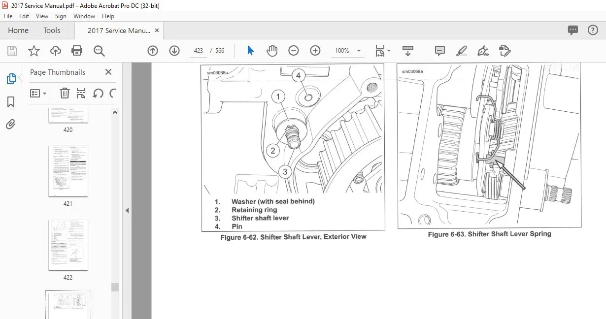
6 4 SHI FTER
Adjustment 6-5
Shifter Rod Adjustment 6-5
Shift Lever Replacement 6-5
TABLE O F CONTENTS
6 5 CLUTCH RELEASE COVER:
MECHANICAL CLUTCH
Removal and DisassemЫy 6-7
Cleaning and lnspection 6-7
AssemЫy and lnstallation 6-8
6 6 TRANSMISSION SIDE COVERS:
HYDRAULIC CLUTCH
Removal 6 -9
lnstallation 6 -9
6 7 SECONDARY CLUTCH ACTUATOR:
HYDRAULIC CLUTCH
Removal 6-1 1
lnstallation 6-1 1
6 8 TRANSMISSION ASSEMBLY
Removal 6 -1 3
DisassemЫy 6-1 4
Shifter Cam/Shifter Forks 6-1 4
Mainshaft 6 -1 5
Countershaft 6 -1 8
Removing Bearing Housing Bearings 6-1 9
Cleaning and lnspection 6-20
AssemЫy 6-20
lnstalling Bearing Housing Bearings 6-20
Countershaft 6-20
Mainshaft 6-21
Shifter Cam/Shifter Forks 6 -21
lnstallation 6 -23
6 9 MAIN DRIVE GEAR AND BEARING
Removal 6-25
Clean and lnspect 6-26
Replace Needle Bearings 6-27
Replace Mainshaft Seal 6-28
1 nstallation 6-28
lnstalling Main Drive Gear Bearing 6-28
lnstalling Main Drive Gear 6-29
lnstalling Main Drive Gear Large Seal 6-30
6 1 О TRANSMISSION CASE
Removal 6 -32
lnstallation 6-32
DisassemЫe 6-33
Remove Shifter Pawl Lever 6-33
Clean and lnspect 6 -33
AssemЫe 6-34
Replace Countershaft Needle Bearing 6-34
lnstall Shifter Pawl Lever 6 -34
E LECTRI C A L
7 1 FASTENER TORQUE VALUES
Fastener Torque Values in this Chapter 7-1
7 2 SPECI FICATIONS: ELECTRICAL
Specifications 7-3
7 3 ELECTRICAL PANEL
General 7-4
Removal: AII But FXSB 7-4
lnstallation: AII Except FXSB 7-5
Removal: FXSB 7-5
lnstallation: FXSB 7 -5
7 4 ELECTRONIC CONTROL MODULE ( ЕСМ)
General 7 -7
Removal: AII But FXSB 7-7
lnstallation: AII But FXSB 7-7
Removal: FXSB 7-7
lnstallation: FXSB 7-7
7 5 BODY CONTROL MODULE ( ВСМ)
General 7-8
ВСМ Configuration 7-8
Removal: AII Except FXSB 7-8
lnstallation: AII Except FXSB 7-8
Removal: FXSB 7 -9
lnstallation: FXSB 7-9
7 6 H -DSSS ACTIVATION
Activation 7-1 0
Fob Assignment 7-1 0
7 7 PERSONAL IDENTI FICATION NUMBER
(PIN)
General 7 -1 1
Changing the PIN 7-1 1
Modifying ап Existing PIN 7-1 1
7 8 HD -SSS MAINTENANCE
Fob Battery 7-1 3
Battery Replacement Schedule 7-1 3
Battery Replacement 7-1 3
Smart Siren {lf Equipped) 7-1 3
Battery Replacement Schedule 7-1 3
Battery Replacement 7-1 3
7 9 SECURITY SIREN
Removal: AII But FXSB 7-1 4
lnstallation: AII But FXSB 7-1 4
Removal: FXSB 7 -1 4
lnstallation: FXSB 7-1 4
7 10 FUSES
Removal 7-1 6
1 nstallation 7-1 6
7 11 IGNITION AND LIGHT SWITCH
General 7-1 7
Removal and lnstallation 7-1 7
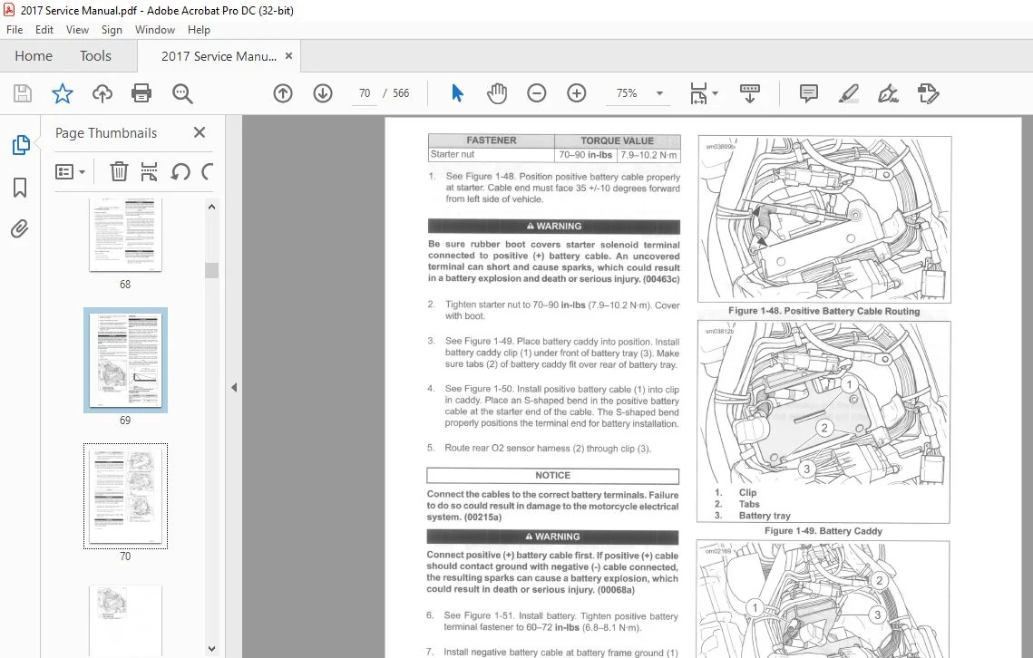
7 12 BATTERY CABLES
Routing Procedure 7-1 8
7 13 STARTER
General 7-20
Removal 7 -20
Drive AssemЫy 7-20
DisassemЫy 7-20
lnspection 7-20
AssemЫy 7-21
Solenoid 7-21
Remove Cover and Plunger 7-21
Short Post Contact: Starter 7-21
Long Post Contact: Battery Positive 7-22
TABLE OF CONTENTS XI
TABLE OF CONTENTS
lnstall Plunger and Cover 7-22
lnstallation 7-22
7 14 HEADLAMP
General 7-24
Headlamp AssemЫy Removal and lnstallation 7-24
Removal 7-24
lnstallation 7-24
Bulb Removal and lnstallation 7-24
FXSB Models 7-25
FLSTC, FLST? FLSTFB, FLSTFBS, FLSTN, FLS, FLSS
Models 7-25
7 15 TAIL LAMP : ALL BUT FLSTN
General 7-27
Bulb Replacement 7-27
Base Replacement 7-27
7 16 TAIL LAMP : FLSTN
Bulb Replacement 7-29
Tail Lamp Replacement 7-29
7 17 AUXILIARY LAMPS : FLSTC, FLSTN
Auxiliary Lamp Bulb 7-31
Removal 7-31
lnstallation 7-31
FLSTC Models 7-31
Auxiliary Lamp Bracket Removal 7-31
Auxiliary Lamp Bracket lnstallation 7-32
Auxiliary Lamp Housing Removal 7-32
Auxiliary Lamp Housing lnstallation 7-32
FLSTN Models 7-33
Auxiliary Lamp Bracket Removal 7-33
Auxiliary Lamp Bracket lnstallation 7-33
Auxiliary Lamp Housing Removal 7-35
Auxiliary Lamp Housing lnstallation 7-35
Adjustment: FLSTC/FLSTN Models 7-36
7 18 TURN SIGNALS AND RUNNING LIGHTS
Bulb Replacement: Bullet Style 7-38
Bulb Replacement: Flat Lens Style 7-38
Lamp Replacement 7-38
AII Models 7-38
Front Turn Signals: FLSTC, FLSTN 7-38
Front Turn Signals: FLSTF, FLSTFB, FLSTFBS, FLS,
FLSS, FXSB 7-38
Rear Turn Signals: AII But FLSTN, FLS, FLSS,
FXSB 7-39
Rear Turn Signals: FLS, FLSS 7-40
Rear Turn Signals: FXSB 7-41
Rear Turn Signals: FLSTN 7-42
7 19 CRANK POSITION SENSOR ( СКР)
General 7-44
Removal 7-44
lnstallation 7-44
7 20 AUTOMATIC COMPRESSION RELEASE
(ACR)
General 7-45
Removal 7-45
lnstallation 7-45
TABLE OF CONTENTS XII
7 21 IGNITION COIL
lnspect Spark Plug СаЫеs 7-47
Removal 7-47
lnstallation 7-47
7 22 SPARK PLUG CABLES
General 7-49
Removal 7-49
lnstallation 7-49
7 23 VOLTAGE REGULATOR
DisassemЫy 7-50
lnstallation 7 -50
7 24 ALTERNATOR
Removal 7-51
Cleaning and lnspection 7-51
lnstallation 7-51
7 25 FUEL GAUGE
General 7-53
Removal 7-53
lnstallation 7-53
7 26 SPEEDOMETER
General 7-55
Removal: AII But FXSB 7-55
lnstallation: AII E xcept FXSB 7-55
Removal: FXSB 7-55
lnstallation: FXSB 7-55
7 27 VEHICLE SPEED SENSOR (VSS)
General 7-57
Removal 7-57
lnstallation 7-57
7 28 WHEEL SPEED SENSORS
Front Wheel Speed Sensor 7-58
Removal 7-58
lnstallation 7-58
Rear Wheel Speed Sensor 7-59
Removal 7-59
lnstallation 7-60
7 29 INDICATOR LAMPS
General 7 -61
Removal: AII But FXSB 7-61
lnstallation: AII But FXSB 7-61
Removal: FXSB 7-61
lnstallation: FXSB 7-62
7 30 NEUTRAL SWITCH
General 7 -63
Removal 7-63
lnstallation 7-63
7 31 OIL PRESSURE SWITCH
General 7-64
Removal 7 -64
lnstallation 7-64
TABLE OF CONTENTS
7 32 REAR STOP LAMP SWITCH REFE RENCE MATE RI A L
General 7-65
Removal 7-65 TOOLS I
lnstallation 7-65 Torque Val ues VII
7 33 HORN lndex X IX
lnspection 7-66
Removal and lnstallation: AII But FXSB 7-66
Removal and lnstallation: FXSB 7-66
7 34 MAIN WIRING HARNESS
Removal 7-68
lnstallation 7-69
7 35 HANDLEBAR CONTROL MODULES
General 7-71
Repair Procedures 7-71
7 36 RIGHT HAND CONTROL MODULE
Removal 7-72
lnstallation 7-72
Front Brake Switch Replacement 7-73
7 37 LE FT HAND CONTROL MODULE
Removal 7-75
lnstallation 7-76
Clutch Switch Replacement 7-76
A P PENDIX А WIRING
д 1 CONNECTORS
Connector Locations А-1
Function/Location А-1
Place and Color А-1
Connector Number A-1
Repair lnstructions А-1
А 2 WIRING DIAGRAMS
Wiring Diagram lnformation A-5
Wire Color Codes А -5
Wiring Diagram Symbols А -5
201 7 Softail Wiring Diagrams A-6
A P PENDIX В REFE RENCE
В 1 LENGTH CONVERSION
Conversion ТаЫе В-1
В 2 FLUID CONVERSION
United States System B-2
Metric System В-2
British lmperial System В-2
В З TORQUE CONVERSION
United States System 8-З
Metric System В-3
В 4 GLOSSARY
Acronyms and Abbreviations В-4
2017 HARLEY DAVIDSON SOFTAIL MODELS SERVICE MANUAL – PDF DOWNLOAD:
PLEASE NOTE:
- This is not a physical manual but a digital manual – meaning no physical copy will be couriered to you. The manual can be yours in the next 2 mins as once you make the payment, you will be directed to the download page IMMEDIATELY.
- This is the same manual used by the dealers inorder to diagnose your vehicle of its faults.
- Require some other service manual or have any queries: please WRITE to us at [email protected]
S.V